EP1162003A2 - Vorrichtung zum Auftragen von Substanzen auf bahnförmiges Material - Google Patents
Vorrichtung zum Auftragen von Substanzen auf bahnförmiges Material Download PDFInfo
- Publication number
- EP1162003A2 EP1162003A2 EP01107006A EP01107006A EP1162003A2 EP 1162003 A2 EP1162003 A2 EP 1162003A2 EP 01107006 A EP01107006 A EP 01107006A EP 01107006 A EP01107006 A EP 01107006A EP 1162003 A2 EP1162003 A2 EP 1162003A2
- Authority
- EP
- European Patent Office
- Prior art keywords
- roller
- application
- main roller
- main
- web
- Prior art date
- Legal status (The legal status is an assumption and is not a legal conclusion. Google has not performed a legal analysis and makes no representation as to the accuracy of the status listed.)
- Granted
Links
Images


Classifications
-
- B—PERFORMING OPERATIONS; TRANSPORTING
- B05—SPRAYING OR ATOMISING IN GENERAL; APPLYING FLUENT MATERIALS TO SURFACES, IN GENERAL
- B05C—APPARATUS FOR APPLYING FLUENT MATERIALS TO SURFACES, IN GENERAL
- B05C1/00—Apparatus in which liquid or other fluent material is applied to the surface of the work by contact with a member carrying the liquid or other fluent material, e.g. a porous member loaded with a liquid to be applied as a coating
- B05C1/04—Apparatus in which liquid or other fluent material is applied to the surface of the work by contact with a member carrying the liquid or other fluent material, e.g. a porous member loaded with a liquid to be applied as a coating for applying liquid or other fluent material to work of indefinite length
- B05C1/08—Apparatus in which liquid or other fluent material is applied to the surface of the work by contact with a member carrying the liquid or other fluent material, e.g. a porous member loaded with a liquid to be applied as a coating for applying liquid or other fluent material to work of indefinite length using a roller or other rotating member which contacts the work along a generating line
- B05C1/0847—Apparatus in which liquid or other fluent material is applied to the surface of the work by contact with a member carrying the liquid or other fluent material, e.g. a porous member loaded with a liquid to be applied as a coating for applying liquid or other fluent material to work of indefinite length using a roller or other rotating member which contacts the work along a generating line the circumferential speed of the coating roller and the work speed having same direction but different value
-
- B—PERFORMING OPERATIONS; TRANSPORTING
- B05—SPRAYING OR ATOMISING IN GENERAL; APPLYING FLUENT MATERIALS TO SURFACES, IN GENERAL
- B05C—APPARATUS FOR APPLYING FLUENT MATERIALS TO SURFACES, IN GENERAL
- B05C1/00—Apparatus in which liquid or other fluent material is applied to the surface of the work by contact with a member carrying the liquid or other fluent material, e.g. a porous member loaded with a liquid to be applied as a coating
- B05C1/04—Apparatus in which liquid or other fluent material is applied to the surface of the work by contact with a member carrying the liquid or other fluent material, e.g. a porous member loaded with a liquid to be applied as a coating for applying liquid or other fluent material to work of indefinite length
- B05C1/08—Apparatus in which liquid or other fluent material is applied to the surface of the work by contact with a member carrying the liquid or other fluent material, e.g. a porous member loaded with a liquid to be applied as a coating for applying liquid or other fluent material to work of indefinite length using a roller or other rotating member which contacts the work along a generating line
- B05C1/0826—Apparatus in which liquid or other fluent material is applied to the surface of the work by contact with a member carrying the liquid or other fluent material, e.g. a porous member loaded with a liquid to be applied as a coating for applying liquid or other fluent material to work of indefinite length using a roller or other rotating member which contacts the work along a generating line the work being a web or sheets
- B05C1/0834—Apparatus in which liquid or other fluent material is applied to the surface of the work by contact with a member carrying the liquid or other fluent material, e.g. a porous member loaded with a liquid to be applied as a coating for applying liquid or other fluent material to work of indefinite length using a roller or other rotating member which contacts the work along a generating line the work being a web or sheets the coating roller co-operating with other rollers, e.g. dosing, transfer rollers
-
- B—PERFORMING OPERATIONS; TRANSPORTING
- B05—SPRAYING OR ATOMISING IN GENERAL; APPLYING FLUENT MATERIALS TO SURFACES, IN GENERAL
- B05C—APPARATUS FOR APPLYING FLUENT MATERIALS TO SURFACES, IN GENERAL
- B05C1/00—Apparatus in which liquid or other fluent material is applied to the surface of the work by contact with a member carrying the liquid or other fluent material, e.g. a porous member loaded with a liquid to be applied as a coating
- B05C1/04—Apparatus in which liquid or other fluent material is applied to the surface of the work by contact with a member carrying the liquid or other fluent material, e.g. a porous member loaded with a liquid to be applied as a coating for applying liquid or other fluent material to work of indefinite length
- B05C1/08—Apparatus in which liquid or other fluent material is applied to the surface of the work by contact with a member carrying the liquid or other fluent material, e.g. a porous member loaded with a liquid to be applied as a coating for applying liquid or other fluent material to work of indefinite length using a roller or other rotating member which contacts the work along a generating line
- B05C1/12—Apparatus in which liquid or other fluent material is applied to the surface of the work by contact with a member carrying the liquid or other fluent material, e.g. a porous member loaded with a liquid to be applied as a coating for applying liquid or other fluent material to work of indefinite length using a roller or other rotating member which contacts the work along a generating line the work being fed round the roller
Definitions
- the invention relates to a device for applying substances to web-like material.
- Such application and coating machines are known and comprise an application roller which extends over the width of the web-shaped material and which applies the substance contained in an application trough to the web-shaped material, the material being passed between the application roller and a counter-abutment roller. It is also known that the application roller is pressed magnetically against the counter-abutment roller by means of an elongated magnetic bar.
- a device is e.g. B. disclosed in EP 0 901 839 A1.
- the object of the invention is to provide a device for applying Develop substances on web-shaped material in such a way that, independently of the processed web width of the material web, no change of the Order role must be made. Another job is that with little effort and without removing the web of material Change of the order substance or an exchange and a cleaning of the Order tub is possible.
- the device comprises a machine frame, a elongated, tubular, rotatingly rubbed main roller, at least one application roll, one extending within the main roll, magnetic pressing device for pressing the application roll against the Main roller, a feed device for wetting the application roll with the substance to be applied and at least one further roller / roller in one Distance to the application roll is arranged on the circumference of the main roller, the web-shaped material between the roller / roller and the main roller passed through and brought into contact with the main roller by the roller / roller is.
- the invention therefore advantageously sees an indirect coating of the roll goods, ie. H. of the sheet material.
- the main advantage over that In addition to the indirect type of coating and the state of the art inexpensive design, in particular the achievable independence from the Web width of the material web to be coated. Since the main roller through the Job roll cannot be coated with the job substance permanently Drying or drying of the order substance take place on the main role. There is also no need to change the material to be coated on the fly different widths the usually necessary rapid change of the Magnetic pressure system or the adjustment of the width of the application roll to the Width of the material web.
- Another advantage of indirect coating is the higher possible Throughput speed of the material web.
- the surface speed of the main roller with the application substance thereon be selected differently from the surface speed of the web-like material, in particular to keep the surface speed of the main roller up to 40% lower compared to the surface speed of the web-like material.
- the adjustability of this speed difference should be possible from zero to 100% before and after. Typical values that can be mentioned are, for example, 100 m / min surface speed of the main roller and 150 to 200 m / min speed of the web-shaped material, the speeds from standstill to the desired speed being able to be regulated as desired. This measure leads to a correspondingly smaller and / or more uniform layer thickness of the application substance on the material web.
- the application roller can be driven be equipped so that the relative speed of the Application roll surface to the main roller surface is adjustable and thus the The thickness of the application layer influences or on the consistency (dynamic Viscosity and tixotropy).
- the job roll can also be done by two or more one above the other or side-by-side application rolls are replaced, thereby creating a indirect application of the main substance to the main roller and thus the Gush (wedge) of the order substance in the area of the narrowing Inlet gusset can be reduced or avoided entirely.
- Both will order rolls arranged one above the other or next to one another by the Magnet system pressed against the main roller.
- the preferably two job roles can essentially in the radial direction to the main roller be arranged one behind the other or side by side.
- the application rollers can be spaced apart, whereas the Spacer rollers have no mutual distance if they are radial to Main roller are arranged one behind the other.
- the roller / roller as a contact roller is formed, the web-shaped together with a further contact roller Brings material into contact with the main roller.
- the order medium is therefore from transfer the magnetically pressed application roller to the main roller and thence by the relative speed of the main roller to the web-shaped Material over a contact distance, which depends on the position of the Contact rollers, transferred to the material.
- the advantage is the inexpensive Production of the order roll. The transfer of the substance to be applied by the magnet system in connection with the Application roll on the main roller very evenly.
- the roller / roller as Pressure roller is formed by means of a magnetic pressure device can be pressed against the main roller.
- the advantage here is that the application of the Substance on the web-like material here is quasi forced, whereby an adjustment of the contact pressure of the contact roller by the magnet system is very well definable and the contact pressure, in particular not from the Tension of the sheet-like material across the width is generally dependent.
- the feed device for the substance to be applied is preferably designed as an application trough which, together with the application roller, can be displaced in the longitudinal direction relative to the main roller and can be pulled out of the device in the manner of a drawer.
- This lateral pulling out of the application tub as compared to the known removal from the front of the device, has the advantage that the web-like material no longer has to be removed for changing the application substance or in the case of cleaning work on the application tub.
- the laterally open and accessible construction means that the trays can also be emptied when installed.
- the application pan is advantageously designed to be tiltable, so that the substance to be applied can be emptied quickly and easily. According to the state of the art, full or filled with tubs had to be laboriously and carefully transported for emptying.
- the device according to the invention is open at the side Access to the front of the rollers / rollers or the application tray possible.
- the main roller is advantageously open on the machine frame by means of outer ring bearings stored.
- This external storage offers the compared to the prior art Advantage of better cooling of the inside of the main roller Magnet system, as a free air circulation within the main roller is possible. Excessive heating of the magnet system reduces its performance, what can now be reduced or avoided due to the open design of the main roller can.
- the preferred diameter of the main roller is 400 mm.
- edge wipers are used provided, which are arranged laterally on the application roll and in defined areas of the job role. Using the two on the side arranged scraper blades is the substance to be applied to the side Edges stripped from the application roll in such a way that the main roller only in one desired and easily adjustable area with the order substance is coated and consequently the material web only on the desired area is provided with the order substance. So there are adjustable, not coated edge areas on the material web.
- FIG 1 shows a first embodiment of the invention Application machine.
- the centerpiece is the main roller 6, which is open on the machine frame 16 (Fig. 3) is mounted. This allows access to the internally hollow one Main roller 6.
- a Magnet system 7 arranged, which consists of a variety of solenoids consists.
- the magnet system 7 acts on a, below the main roller 6 arranged, application roller 8 and pushes or pulls it into contact with the Main roller 6.
- a Feeder 9 for the order substance can the order pan accordingly be filled.
- a surplus of the order substance is indicated by a Overflow pan or return pan 12 collected and back into the circuit returned.
- the order tray 10 can in the vertical direction by a Adjustment device 11 can be adjusted, whereby the immersion depth of the application roll 8 can be set in the order substance.
- Two contact rollers 1, 3 are preferably arranged above the main roller, over which the material web 4 to be coated is guided.
- the contact roller 3 is linearly adjustable up to a maximum stop 13, whereby the material web 4 can be brought into contact with the main roller 6.
- the main roller 6 is driven to rotate in the direction indicated by the arrow, the material web 4 with the corresponding speed of the Main roller 6 is guided past the surface.
- the order substance located in the order tub 10 is from the Order roll 8 added, the magnet system 7 to the main roller 6th is pressed. As a result, the application substance 15 is applied to the surface of the Main roller 6 transferred.
- the application roller 8 runs passively with the main roller 6 with, but can also have its own drive, so that this with a defined relative speed to the main roller 6 runs.
- the order substance 15 is carried along by the main roller 6 and onto the material web 4 transferred, which also at a relative speed to the main roller this runs along.
- the material web is coated within one Contact section 14, the length of which depends essentially on the position of the Feed roller 4 depends.
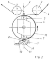
- FIG. 2 A second embodiment of the invention is shown in FIG. 2.
- the same components are provided with the same reference numbers.
- the Operation of the main roller 6, the application roller 8 and the application tray 10 and its associated parts correspond to those in connection with FIG. 1 described mode of operation.
- the way is different Transfer of the order substance 15 from the main roller 6 to the material web 4.
- the contact rollers 1 and 3 are provided, but here mainly work as deflection rollers.
- a pressure roller 2 is provided, which via a second Magnet system 5 can be pressed against the main roller 6 with a definable force.
- the Magnet system 5 is also arranged within the main roller 6 and can form a unit with the magnet system 7.
- the pressure roller 2 is now the web of material 4 pressed with a defined force on the main roller 6, whereby the Transfer of the order substance 15 located on the main roller 6 to the Material web 4 can be controlled in a defined manner. Depending on the contact pressure The pressure roller 2 can control the coating thickness on the material web 4 become.
- the transfer of the order substance from the main roller 6 to the Paper is therefore compulsory and in particular is not dependent on the Tension of the material web seen across its width. This one too Embodiment can the relative speed between the main roller 6 and Material web 4 can be regulated by different drive speeds the main role 6 and the material web 4.
- Both embodiments shown in Figures 1 and 2 stand out through an indirect transfer of the order substance to the material web, since the order substance first of all from the application roll 8 to the main roller 6 is transferred and in a second step from the main roller 6 to the Material web.
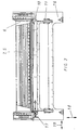
- the basic structure of the application machine can be seen in FIG. 3 where it can be seen that the application machine is a space-saving Arrangement.
- the main roller 6 is open on a machine frame 16 stored.
- the contact rollers 1, 3 and Pressure roller 2 not shown. Depending on the embodiment, these are above the Main roller 6 arranged.
- the magnet systems 7, 5 are within the main roller arranged.
- the order tray 10 below the main roller 6 is the order tray 10, in which the Application roll 8 (not shown) is arranged.
- the order tray 10 can be adjusted in the vertical direction 18.
- the Tray adjustment 17 can the order tray 10 together with the Application roller 8 laterally in the direction of arrow 19 from the machine frame 16 pulled out and inserted.
- This side pulling out of the Order tray 10 or order roll 8 also has the advantage that a Step arrangement of several machines is possible. Due to the possibility of lateral tub manipulation can be a staircase design of several Contract machines are done.
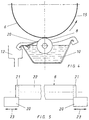
- FIGS. 4 and 5 show the possibility of arranging an edge wiping knife 20 on both sides of the application roller 8, which edge abut against the application roller 8 and wipes off the substance 15 to be applied to the main roller laterally at the edges of the application roller 8.
- the areas 21 on the edges of the application roll 8 therefore remain free of the order substance 16, so that no order substance 15 is applied to the main roller 6 there either.
- the scraper blades 20 can be moved parallel to the longitudinal extent of the application roller 8, as indicated by the double arrows 23 in FIG. 5. As a result, the width of the effective region 21 of the edge wipers 20 on the application roller 8 can be adjusted.
- the main roller 6 is wetted with the application substance 15 only in the desired and easily adjustable region 22, so that the material web 4 is also coated with the application substance only in the desired, set region 22.
- the edge wipers 20 thus determine the width of the Order substance 15 coated area 22 of the material web, the Edges of the material web 4 e.g. in a range of 50 mm from the Order substance 15 can be kept free.
- Figure 6 shows that the main roller 6 by means of outer ring bearings 24 on Machine frame 16 is mounted.
- This external storage offers compared to State of the art has the advantage of better cooling of the inside of the Main roller 6 arranged magnet system 7, because of the open storage free air circulation within the main roller 6 is possible.
- the main roller 6 will driven in the example shown by a drive 25 via a toothed belt.
Landscapes
- Coating Apparatus (AREA)
- Treatment Of Fiber Materials (AREA)
- Heating, Cooling, Or Curing Plastics Or The Like In General (AREA)
Abstract
Description
Derartige Auftrags- und Beschichtungsmaschinen sind bekannt und umfassen eine über die Breite des bahnförmigen Materials sich erstreckende Auftragswalze, welche die in einer Auftragswanne enthaltene Substanz auf dem bahnförmigen Material aufträgt, wobei das Material zwischen der Auftragswalze und einer Gegenanlagewalze hindurchgeführt wird. Dabei ist es ferner bekannt, dass die Auftragswalze mittels eines langgestreckten Magnetbalkens magnetisch gegen die Gegenanlagewalze gepresst wird. Eine derartige Vorrichtung ist z. B. in der EP 0 901 839 A1 offenbart.
Als typische Werte können beispielsweise 100 m/min Oberflächengeschwindigkeit der Hauptwalze und 150 bis 200 m/min Geschwindigkeit des bahnförmigen Materials genannt, wobei die Geschwindigkeiten von Stillstand bis Sollgeschwindigkeit beliebig regelbar sein müssen.
Diese Maßnahme führt zu einer entsprechend geringeren und/oder gleichmäßigeren Schichtdicke der Auftragssubstanz auf der Materialbahn.
Gemäss dem Stand der Technik mussten volle bzw. mit Auftragssubstanzen gefüllte Wannen mühsam und sorgfältig zum Entleeren transportiert werden.
- Fig. 1:
- schematisch einen Schnitt durch die Vorrichtung in einer ersten Ausführungsform;
- Fig. 2:
- schematisch einen Schnitt durch die Vorrichtung in einer zweiten Ausführungsform;
- Fig. 3:
- eine vereinfachte Vorderansicht der Vorrichtung;
- Fig. 4:
- schematisch einen Schnitt durch die Vorrichtung im Bereich der Auftragsrolle mit zusätzlicher Randabstreifrakel;
- Fig. 5:
- schematisch eine Draufsicht auf die Auftragsrolle mit Radabstreifrakeln;
- Fig. 6:
- eine perspektivische Ansicht des Maschinengestells mit darin gelagerter Hauptwalze.
Die Randabstreifrakeln 20 sind parallel zur Längserstreckung der Auftragsrolle 8 verschiebbar, wie es mit den Doppelpfeilen 23 in Figur 5 angedeutet ist. Dadurch ist die Breite des wirksamen Bereichs 21 der Randabstreifrakeln 20 auf der Auftragsrolle 8 einstellbar. Die Hauptwalze 6 wird nur in dem gewünschten und einfach einstellbaren Bereich 22 mit der Auftragssubstanz 15 benetzt, so daß die Materialbahn 4 ebenfalls nur im gewünschten, eingestellten Bereich 22 mit der Auftragssubstanz beschichtet wird.
- 1
- Anlegewalze
- 2
- Anpressrolle
- 3
- Anlegewalze
- 4
- Materialbahn
- 5
- Magnetsystem 2
- 6
- Hauptwalze
- 7
- Magnetsystem 1
- 8
- Auftragsrolle
- 9
- Zuführung
- 10
- Auftragswanne
- 11
- Verstelleinrichtung (Wanne)
- 12
- Überlauf/Rücklauf
- 13
- Anschlag
- 14
- Kontaktstrecke
- 15
- Auftragssubstanz
- 16
- Maschinengerüst
- 17
- Wannenverstellung
- 18
- Pfeilrichtung
- 19
- Pfeilrichtung
- 20
- Randabstreifrakel
- 21
- Bereich
- 22
- Bereich
- 23
- Pfeilrichtung
- 24
- Außenringlager
- 25
- Antrieb
Claims (14)
- Vorrichtung zum Auftragen von Substanzen auf bahnförmiges Material welche umfasst:ein Maschinengerüst (16),eine langgestreckte, rohrförmig ausgebildete rotierend angetriebene Hauptwalze (6);mindestens eine Auftragsrolle (8);eine innerhalb der Hauptwalze (6) sich erstreckende, magnetische Anpresseinrichtung (7) zum Anpressen der Auftragsrolle (8) an die Hauptwalze (6);eine Zuführeinrichtung (10) zum Benetzen der Auftragsrolle (8) mit der aufzutragenden Substanz; undmindestens eine weitere Rolle/ Walze (1; 2; 3), die in einem Abstand zur Auftragsrolle (8) am Umfang der Hauptwalze angeordnet ist, wobei das bahnförmige Material (4) zwischen der Rolle/Walze (1; 2; 3) und der Hauptwalze (6) hindurchgeführt und durch die Rolle/Walze in Kontakt mit der Hauptwalze bringbar ist.
- Vorrichtung nach Anspruch 1, dadurch gekennzeichnet, dass die Hauptwalze (6) und das bahnförmige Material (4) unterschiedliche Oberflächengeschwindigkeiten aufweisen.
- Vorrichtung nach einem der vorhergehenden Ansprüche, dadurch gekennzeichnet, dass die jeweiligen Oberflächengeschwindigkeiten der Hauptwalze (6) und des bahnförmigen Materials (4) einstellbar sind.
- Vorrichtung nach einem der vorhergehenden Ansprüche, dadurch gekennzeichnet, dass die Auftragsrolle (8) einen Antrieb umfasst und gegenüber der Hauptwalze (6) mit unterschiedlicher Drehgeschwindigkeit und/oder Drehrichtung antreibbar ist.
- Vorrichtung nach einem der vorhergehenden Ansprüche, dadurch gekennzeichnet, dass mindestens zwei Auftragsrollen (8) ohne oder in geringem gegenseitigen Abstand angeordnet sind.
- Vorrichtung nach einem der vorhergehenden Ansprüche, dadurch gekennzeichnet, dass die Rolle/Walze als Anlegewalze (3) ausgebildet ist, die zusammen mit einer weiteren Anlegewalze (1) das bahnförmige Material (4) in Kontakt mit der Hauptwalze (6) bringt.
- Vorrichtung nach einem der vorhergehenden Ansprüche, dadurch gekennzeichnet, dass die Rolle/Walze als Anpressrolle (2) ausgebildet ist, die mittels einer magnetischen Anpresseinrichtung (5) gegen die Hauptwalze (6) pressbar ist.
- Vorrichtung nach einem der vorhergehenden Ansprüche, dadurch gekennzeichnet, dass die Zuführeinrichtung für die aufzutragende Substanz als Auftragswanne (10) ausgebildet ist.
- Vorrichtung nach einem der vorhergehenden Ansprüche, dadurch gekennzeichnet, dass die Auftragsrolle (8) und die Auftragswanne (10) in Längsrichtung gegenüber der Hauptwalze (6) verschiebbar und schubladenartig aus der Vorrichtung ausziehbar sind.
- Vorrichtung nach einem der vorhergehenden Ansprüche, dadurch gekennzeichnet, dass die Auftragswanne (10) im eingefahrenen Zustand kippbar ausgeführt ist und derart eine einfache und rasche Entleerung der aufzutragenden Substanz (15) ermöglicht.
- Vorrichtung nach einem der vorhergehenden Ansprüche, dadurch gekennzeichnet, dass zumindest eine Stirnseite der Rollen/Walzen (6; 8) und der Auftragswanne (10) seitlich offen zugänglich ist.
- Vorrichtung nach einem der vorhergehenden Ansprüche, dadurch gekennzeichnet, dass die Hauptwalze (6) mittels Außenlagern (24) offen am Maschinengerüst (16) gelagert ist.
- Vorrichtung nach einem der vorhergehenden Ansprüche, dadurch gekennzeichnet, dass der Durchmesser der Hauptwalze (6) etwa 400 mm beträgt.
- Vorrichtung nach einem der vorhergehenden Ansprüche, dadurch gekennzeichnet, dass Randabstreifrakeln (20) vorgesehen sind, die seitlich an der Auftragsrolle (8) verschiebbar angeordnet sind und in definierten Bereichen (21) an der Auftragsrolle (8) anliegen.
Applications Claiming Priority (2)
| Application Number | Priority Date | Filing Date | Title |
|---|---|---|---|
| DE20010388U DE20010388U1 (de) | 2000-06-09 | 2000-06-09 | Vorrichtung zum Auftragen von Substanzen auf bahnförmiges Material |
| DE20010388U | 2000-06-09 |
Publications (4)
| Publication Number | Publication Date |
|---|---|
| EP1162003A2 true EP1162003A2 (de) | 2001-12-12 |
| EP1162003A3 EP1162003A3 (de) | 2003-01-02 |
| EP1162003B1 EP1162003B1 (de) | 2004-04-28 |
| EP1162003B2 EP1162003B2 (de) | 2009-08-26 |
Family
ID=7942707
Family Applications (1)
| Application Number | Title | Priority Date | Filing Date |
|---|---|---|---|
| EP01107006A Expired - Lifetime EP1162003B2 (de) | 2000-06-09 | 2001-03-21 | Vorrichtung zum Auftragen von Substanzen auf bahnförmiges Material |
Country Status (3)
| Country | Link |
|---|---|
| EP (1) | EP1162003B2 (de) |
| AT (1) | ATE265276T1 (de) |
| DE (2) | DE20010388U1 (de) |
Cited By (4)
| Publication number | Priority date | Publication date | Assignee | Title |
|---|---|---|---|---|
| WO2005105900A1 (de) * | 2004-04-28 | 2005-11-10 | Se Tylose Gmbh & Co. Kg | Verfahren und vorrichtung zum mahlen von cellulose |
| EP1614483A3 (de) * | 2004-07-05 | 2006-11-15 | Jakob Weiss & Sohne Maschinenfabrik Gmbh | Rakelvorrichtung und Rakelverfahren |
| WO2010009778A1 (de) * | 2008-07-24 | 2010-01-28 | Khs Ag | Applikatoreinrichtung |
| ITFI20120137A1 (it) * | 2012-06-29 | 2013-12-30 | Perini Fabio Spa | "dispositivo per l'applicazione di una sostanza liquida su un materiale nastriforme e relativo metodo" |
Families Citing this family (4)
| Publication number | Priority date | Publication date | Assignee | Title |
|---|---|---|---|---|
| DE102004032568B4 (de) * | 2004-07-05 | 2007-09-20 | Jakob Weiß & Söhne Maschinenfabrik GmbH | Rakelvorrichtung und Rakelverfahren |
| DE102004039732A1 (de) * | 2004-08-17 | 2006-02-23 | Man Roland Druckmaschinen Ag | Farbdosierung durch Magnetkraft |
| DE102005062527A1 (de) | 2005-12-16 | 2007-06-21 | Gebr. Schmid Gmbh & Co. | Vorrichtung und Verfahren zur Oberflächenbehandlung von Substraten |
| DE102005062528A1 (de) * | 2005-12-16 | 2007-06-21 | Gebr. Schmid Gmbh & Co. | Vorrichtung und Verfahren zur Oberflächenbehandlung von Substraten |
Citations (1)
| Publication number | Priority date | Publication date | Assignee | Title |
|---|---|---|---|---|
| EP0901839A2 (de) | 1997-09-11 | 1999-03-17 | Johannes Zimmer | Vorrichtung zum Auftragen von Flüssigkeiten auf ein Substrat |
Family Cites Families (11)
| Publication number | Priority date | Publication date | Assignee | Title |
|---|---|---|---|---|
| GB1472709A (en) * | 1975-03-10 | 1977-05-04 | Wiggins Teape Ltd | Coating apparatus |
| DE2554318C3 (de) * | 1975-12-03 | 1981-11-26 | Agfa-Gevaert Ag, 5090 Leverkusen | Verfahren und Vorrichtung zum Beschichten von Magnetbändern mit Hilfe des Rasterdruckverfahrens |
| AT374379B (de) * | 1982-03-29 | 1984-04-10 | Zimmer Johannes | Vorrichtung zum gleichmaessigen auftragen bestimmbarer fluessigkeitsmengen |
| AT378151B (de) * | 1983-10-07 | 1985-06-25 | Johannes Zimmer | Druck- und auftragsmaschine fuer fliessfaehige medien auf warenbahnen |
| AT386761B (de) † | 1986-04-30 | 1988-10-10 | Zimmer Johannes | Vorrichtung zum auftragen geringer oder geringster mengen von fliessfaehigen substanzen |
| AT386968B (de) * | 1986-12-05 | 1988-11-10 | Zimmer Johannes | Vorrichtung zum auftragen bestimmbarer mengen von fliessfaehigen medien |
| JP2614119B2 (ja) * | 1989-10-16 | 1997-05-28 | 富士写真フイルム株式会社 | 塗布装置及び方法 |
| DE4013464C2 (de) * | 1990-04-27 | 1995-01-05 | Heidelberger Druckmasch Ag | Gummieren der Druckform einer Druckmaschine |
| DE4014463A1 (de) * | 1990-05-07 | 1991-11-14 | Jagenberg Ag | Vorrichtung zum beschichten einer materialbahn, insbesondere einer papier- oder kartonbahn |
| DE19549254A1 (de) * | 1994-12-27 | 1996-07-04 | Johannes Zimmer | Vorrichtung zum Auftragen bestimmter Flüssigkeitsmengen |
| ATE210223T1 (de) * | 1995-07-29 | 2001-12-15 | Jagenberg Papiertech Gmbh | Auftragsystem für eine vorrichtung zum beschichten einer papier- oder kartonbahn |
-
2000
- 2000-06-09 DE DE20010388U patent/DE20010388U1/de not_active Expired - Lifetime
-
2001
- 2001-03-21 AT AT01107006T patent/ATE265276T1/de not_active IP Right Cessation
- 2001-03-21 DE DE50102100T patent/DE50102100D1/de not_active Expired - Fee Related
- 2001-03-21 EP EP01107006A patent/EP1162003B2/de not_active Expired - Lifetime
Patent Citations (1)
| Publication number | Priority date | Publication date | Assignee | Title |
|---|---|---|---|---|
| EP0901839A2 (de) | 1997-09-11 | 1999-03-17 | Johannes Zimmer | Vorrichtung zum Auftragen von Flüssigkeiten auf ein Substrat |
Cited By (5)
| Publication number | Priority date | Publication date | Assignee | Title |
|---|---|---|---|---|
| WO2005105900A1 (de) * | 2004-04-28 | 2005-11-10 | Se Tylose Gmbh & Co. Kg | Verfahren und vorrichtung zum mahlen von cellulose |
| US7578458B2 (en) | 2004-04-28 | 2009-08-25 | Se Tylose Gmbh & Co., Kg | Method and device for grinding cellulose |
| EP1614483A3 (de) * | 2004-07-05 | 2006-11-15 | Jakob Weiss & Sohne Maschinenfabrik Gmbh | Rakelvorrichtung und Rakelverfahren |
| WO2010009778A1 (de) * | 2008-07-24 | 2010-01-28 | Khs Ag | Applikatoreinrichtung |
| ITFI20120137A1 (it) * | 2012-06-29 | 2013-12-30 | Perini Fabio Spa | "dispositivo per l'applicazione di una sostanza liquida su un materiale nastriforme e relativo metodo" |
Also Published As
| Publication number | Publication date |
|---|---|
| DE20010388U1 (de) | 2001-10-11 |
| EP1162003B2 (de) | 2009-08-26 |
| EP1162003A3 (de) | 2003-01-02 |
| ATE265276T1 (de) | 2004-05-15 |
| DE50102100D1 (de) | 2004-06-03 |
| EP1162003B1 (de) | 2004-04-28 |
Similar Documents
| Publication | Publication Date | Title |
|---|---|---|
| DE69114042T2 (de) | Verfahren zur Begrenzung der Breite der Beschichtung bei der Beschichtung von Papier oder Pappe und Vorrichtung zur Durchführung dieses Verfahrens. | |
| DE2935413C2 (de) | Vorrichtung zum kontinuierlichen Behandeln einer textilen oder ähnlichen Warenbahn mit einem Behandlungsmedium in Schaumform | |
| DE69401751T2 (de) | Vorrichtung und verfahren zum auftragen von klebstoff auf einen wickelkern für bahnmaterial | |
| CH626000A5 (de) | ||
| DE4446308C2 (de) | Vorrichtung zum Auftragen eines flüssigen oder pastösen Mediums auf eine laufende Materialbahn | |
| DD149167A5 (de) | Vorrichtung zum auftragen von schaum auf eine laufende bahn | |
| EP0108887B1 (de) | Vorrichtung zum gleichmässigen Auftragen von fliessfähigen Medien | |
| EP0408704B2 (de) | Anordnung zum auftragen von substanzen auf bahnförmiges material | |
| EP1162003B1 (de) | Vorrichtung zum Auftragen von Substanzen auf bahnförmiges Material | |
| DE3010038A1 (de) | Vorrichtung zum kontinuierlichen behandeln von textilen u.ae. warenbahnen mit schaum | |
| EP1043119A2 (de) | Verfahren und Vorrichtung zum Aussenrundschleifen dünnwandiger Rohre | |
| DE3928439C2 (de) | Durchbiegungseinstellwalze | |
| DE3419590C2 (de) | ||
| DE19827712B4 (de) | Vorrichtung zum direkten oder indirekten Auftragen eines flüssigen oder pastösen Auftragsmediums auf eine laufende Materialbahn | |
| EP0028608B1 (de) | Vorrichtung mit magnetisch bewirkter anpresskraft | |
| EP0047484B1 (de) | Foulard | |
| AT394665B (de) | Vielzweck-bearbeitungs-vorrichtung | |
| DE3618935C2 (de) | ||
| EP0757129A1 (de) | Auftragsystem für eine Vorrichtung zum Beschichten einer Papier- oder Kartonbahn | |
| DE4440948A1 (de) | Verfahren zum Aufführen einer Papierbahn in eine Papiermaschine, Naßpartie einer Papiermaschine sowie Saugwalze für eine Papiermaschine | |
| DE69018135T2 (de) | Befeuchtungsvorrichtung für bandförmiges Material, insbesondere Papier. | |
| DE19604934A1 (de) | Auftragsystem für eine Vorrichtung zum Beschichten einer Papier- oder Kartonbahn | |
| DE10214392A1 (de) | Verfahren und Vorrichtung zum Betreiben einer Schaberklinge | |
| DE69101808T2 (de) | Klebstoffauftrageinrichtung für durchlaufende Warenbahnen in einem Apparat zur Herstellung von Papiererzeugnissen. | |
| DE29609053U1 (de) | Vorrichtung zum direkten oder indirekten Auftragen oder Enddosieren eines flüssigen oder pastösen Mediums auf eine laufende Materialbahn |
Legal Events
| Date | Code | Title | Description |
|---|---|---|---|
| PUAI | Public reference made under article 153(3) epc to a published international application that has entered the european phase |
Free format text: ORIGINAL CODE: 0009012 |
|
| AK | Designated contracting states |
Kind code of ref document: A2 Designated state(s): AT BE CH CY DE DK ES FI FR GB GR IE IT LI LU MC NL PT SE TR |
|
| AX | Request for extension of the european patent |
Free format text: AL;LT;LV;MK;RO;SI |
|
| PUAL | Search report despatched |
Free format text: ORIGINAL CODE: 0009013 |
|
| AK | Designated contracting states |
Kind code of ref document: A3 Designated state(s): AT BE CH CY DE DK ES FI FR GB GR IE IT LI LU MC NL PT SE TR |
|
| AX | Request for extension of the european patent |
Free format text: AL;LT;LV;MK;RO;SI |
|
| RIC1 | Information provided on ipc code assigned before grant |
Free format text: 7B 05C 1/08 A, 7B 05C 1/12 B |
|
| 17P | Request for examination filed |
Effective date: 20030328 |
|
| AKX | Designation fees paid |
Designated state(s): AT BE CH CY DE DK ES FI FR GB GR IE IT LI LU MC NL PT SE TR |
|
| GRAP | Despatch of communication of intention to grant a patent |
Free format text: ORIGINAL CODE: EPIDOSNIGR1 |
|
| GRAS | Grant fee paid |
Free format text: ORIGINAL CODE: EPIDOSNIGR3 |
|
| GRAA | (expected) grant |
Free format text: ORIGINAL CODE: 0009210 |
|
| AK | Designated contracting states |
Kind code of ref document: B1 Designated state(s): AT BE CH CY DE DK ES FI FR GB GR IE IT LI LU MC NL PT SE TR |
|
| PG25 | Lapsed in a contracting state [announced via postgrant information from national office to epo] |
Ref country code: FI Free format text: LAPSE BECAUSE OF FAILURE TO SUBMIT A TRANSLATION OF THE DESCRIPTION OR TO PAY THE FEE WITHIN THE PRESCRIBED TIME-LIMIT Effective date: 20040428 Ref country code: TR Free format text: LAPSE BECAUSE OF FAILURE TO SUBMIT A TRANSLATION OF THE DESCRIPTION OR TO PAY THE FEE WITHIN THE PRESCRIBED TIME-LIMIT Effective date: 20040428 Ref country code: IE Free format text: LAPSE BECAUSE OF FAILURE TO SUBMIT A TRANSLATION OF THE DESCRIPTION OR TO PAY THE FEE WITHIN THE PRESCRIBED TIME-LIMIT Effective date: 20040428 |
|
| REG | Reference to a national code |
Ref country code: GB Ref legal event code: FG4D Free format text: NOT ENGLISH |
|
| REG | Reference to a national code |
Ref country code: CH Ref legal event code: EP |
|
| REG | Reference to a national code |
Ref country code: IE Ref legal event code: FG4D Free format text: GERMAN |
|
| REF | Corresponds to: |
Ref document number: 50102100 Country of ref document: DE Date of ref document: 20040603 Kind code of ref document: P |
|
| PG25 | Lapsed in a contracting state [announced via postgrant information from national office to epo] |
Ref country code: GR Free format text: LAPSE BECAUSE OF FAILURE TO SUBMIT A TRANSLATION OF THE DESCRIPTION OR TO PAY THE FEE WITHIN THE PRESCRIBED TIME-LIMIT Effective date: 20040728 Ref country code: DK Free format text: LAPSE BECAUSE OF FAILURE TO SUBMIT A TRANSLATION OF THE DESCRIPTION OR TO PAY THE FEE WITHIN THE PRESCRIBED TIME-LIMIT Effective date: 20040728 |
|
| PG25 | Lapsed in a contracting state [announced via postgrant information from national office to epo] |
Ref country code: ES Free format text: LAPSE BECAUSE OF FAILURE TO SUBMIT A TRANSLATION OF THE DESCRIPTION OR TO PAY THE FEE WITHIN THE PRESCRIBED TIME-LIMIT Effective date: 20040808 |
|
| REG | Reference to a national code |
Ref country code: SE Ref legal event code: TRGR |
|
| REG | Reference to a national code |
Ref country code: CH Ref legal event code: NV Representative=s name: LUCHS & PARTNER PATENTANWAELTE |
|
| GBT | Gb: translation of ep patent filed (gb section 77(6)(a)/1977) |
Effective date: 20040811 |
|
| REG | Reference to a national code |
Ref country code: IE Ref legal event code: FD4D |
|
| ET | Fr: translation filed | ||
| PLAQ | Examination of admissibility of opposition: information related to despatch of communication + time limit deleted |
Free format text: ORIGINAL CODE: EPIDOSDOPE2 |
|
| PLAR | Examination of admissibility of opposition: information related to receipt of reply deleted |
Free format text: ORIGINAL CODE: EPIDOSDOPE4 |
|
| PLAZ | Examination of admissibility of opposition: despatch of communication + time limit |
Free format text: ORIGINAL CODE: EPIDOSNOPE2 |
|
| PLBQ | Unpublished change to opponent data |
Free format text: ORIGINAL CODE: EPIDOS OPPO |
|
| PLBI | Opposition filed |
Free format text: ORIGINAL CODE: 0009260 |
|
| PGFP | Annual fee paid to national office [announced via postgrant information from national office to epo] |
Ref country code: BE Payment date: 20050302 Year of fee payment: 5 |
|
| PLAQ | Examination of admissibility of opposition: information related to despatch of communication + time limit deleted |
Free format text: ORIGINAL CODE: EPIDOSDOPE2 |
|
| PLAR | Examination of admissibility of opposition: information related to receipt of reply deleted |
Free format text: ORIGINAL CODE: EPIDOSDOPE4 |
|
| PLBQ | Unpublished change to opponent data |
Free format text: ORIGINAL CODE: EPIDOS OPPO |
|
| PLAB | Opposition data, opponent's data or that of the opponent's representative modified |
Free format text: ORIGINAL CODE: 0009299OPPO |
|
| PG25 | Lapsed in a contracting state [announced via postgrant information from national office to epo] |
Ref country code: IT Free format text: LAPSE BECAUSE OF NON-PAYMENT OF DUE FEES Effective date: 20050321 Ref country code: CY Free format text: LAPSE BECAUSE OF FAILURE TO SUBMIT A TRANSLATION OF THE DESCRIPTION OR TO PAY THE FEE WITHIN THE PRESCRIBED TIME-LIMIT Effective date: 20050321 Ref country code: LU Free format text: LAPSE BECAUSE OF NON-PAYMENT OF DUE FEES Effective date: 20050321 |
|
| PGFP | Annual fee paid to national office [announced via postgrant information from national office to epo] |
Ref country code: FR Payment date: 20050324 Year of fee payment: 5 |
|
| PGFP | Annual fee paid to national office [announced via postgrant information from national office to epo] |
Ref country code: SE Payment date: 20050330 Year of fee payment: 5 |
|
| PG25 | Lapsed in a contracting state [announced via postgrant information from national office to epo] |
Ref country code: MC Free format text: LAPSE BECAUSE OF NON-PAYMENT OF DUE FEES Effective date: 20050331 |
|
| PLAQ | Examination of admissibility of opposition: information related to despatch of communication + time limit deleted |
Free format text: ORIGINAL CODE: EPIDOSDOPE2 |
|
| PLAR | Examination of admissibility of opposition: information related to receipt of reply deleted |
Free format text: ORIGINAL CODE: EPIDOSDOPE4 |
|
| PLAX | Notice of opposition and request to file observation + time limit sent |
Free format text: ORIGINAL CODE: EPIDOSNOBS2 |
|
| PLBQ | Unpublished change to opponent data |
Free format text: ORIGINAL CODE: EPIDOS OPPO |
|
| PLAB | Opposition data, opponent's data or that of the opponent's representative modified |
Free format text: ORIGINAL CODE: 0009299OPPO |
|
| 26 | Opposition filed |
Opponent name: J. ZIMMER MASCHINENBAU GES. M.B.H. Effective date: 20050128 |
|
| PLBB | Reply of patent proprietor to notice(s) of opposition received |
Free format text: ORIGINAL CODE: EPIDOSNOBS3 |
|
| R26 | Opposition filed (corrected) |
Opponent name: J. ZIMMER MASCHINENBAU GES. M.B.H. Effective date: 20050128 |
|
| R26 | Opposition filed (corrected) |
Opponent name: J. ZIMMER MASCHINENBAU GES. M.B.H. Effective date: 20050128 |
|
| NLR1 | Nl: opposition has been filed with the epo |
Opponent name: J. ZIMMER MASCHINENBAU GES. M.B.H. |
|
| PGFP | Annual fee paid to national office [announced via postgrant information from national office to epo] |
Ref country code: CH Payment date: 20050610 Year of fee payment: 5 |
|
| NLR1 | Nl: opposition has been filed with the epo |
Opponent name: J. ZIMMER MASCHINENBAU GES. M.B.H. |
|
| NLR1 | Nl: opposition has been filed with the epo |
Opponent name: J. ZIMMER MASCHINENBAU GES. M.B.H. |
|
| PG25 | Lapsed in a contracting state [announced via postgrant information from national office to epo] |
Ref country code: SE Free format text: LAPSE BECAUSE OF NON-PAYMENT OF DUE FEES Effective date: 20060322 |
|
| PGFP | Annual fee paid to national office [announced via postgrant information from national office to epo] |
Ref country code: NL Payment date: 20060328 Year of fee payment: 6 |
|
| PG25 | Lapsed in a contracting state [announced via postgrant information from national office to epo] |
Ref country code: BE Free format text: LAPSE BECAUSE OF NON-PAYMENT OF DUE FEES Effective date: 20060331 Ref country code: LI Free format text: LAPSE BECAUSE OF NON-PAYMENT OF DUE FEES Effective date: 20060331 Ref country code: CH Free format text: LAPSE BECAUSE OF NON-PAYMENT OF DUE FEES Effective date: 20060331 |
|
| REG | Reference to a national code |
Ref country code: CH Ref legal event code: PL |
|
| EUG | Se: european patent has lapsed | ||
| REG | Reference to a national code |
Ref country code: FR Ref legal event code: ST Effective date: 20061130 |
|
| GBPC | Gb: european patent ceased through non-payment of renewal fee |
Effective date: 20070321 |
|
| NLV4 | Nl: lapsed or anulled due to non-payment of the annual fee |
Effective date: 20071001 |
|
| BERE | Be: lapsed |
Owner name: *TIMATEC MASCHINEN UND ANLAGENBAU G.M.B.H. Effective date: 20060331 |
|
| PG25 | Lapsed in a contracting state [announced via postgrant information from national office to epo] |
Ref country code: PT Free format text: LAPSE BECAUSE OF NON-PAYMENT OF DUE FEES Effective date: 20040928 |
|
| PG25 | Lapsed in a contracting state [announced via postgrant information from national office to epo] |
Ref country code: NL Free format text: LAPSE BECAUSE OF NON-PAYMENT OF DUE FEES Effective date: 20071001 Ref country code: FR Free format text: LAPSE BECAUSE OF NON-PAYMENT OF DUE FEES Effective date: 20060331 |
|
| PG25 | Lapsed in a contracting state [announced via postgrant information from national office to epo] |
Ref country code: GB Free format text: LAPSE BECAUSE OF NON-PAYMENT OF DUE FEES Effective date: 20070321 |
|
| PGFP | Annual fee paid to national office [announced via postgrant information from national office to epo] |
Ref country code: AT Payment date: 20080303 Year of fee payment: 8 |
|
| PGFP | Annual fee paid to national office [announced via postgrant information from national office to epo] |
Ref country code: DE Payment date: 20080214 Year of fee payment: 8 |
|
| PGFP | Annual fee paid to national office [announced via postgrant information from national office to epo] |
Ref country code: GB Payment date: 20060220 Year of fee payment: 6 |
|
| PUAH | Patent maintained in amended form |
Free format text: ORIGINAL CODE: 0009272 |
|
| STAA | Information on the status of an ep patent application or granted ep patent |
Free format text: STATUS: PATENT MAINTAINED AS AMENDED |
|
| 27A | Patent maintained in amended form |
Effective date: 20090826 |
|
| AK | Designated contracting states |
Kind code of ref document: B2 Designated state(s): AT BE CH CY DE DK ES FI FR GB GR IE IT LI LU MC NL PT SE TR |
|
| REG | Reference to a national code |
Ref country code: ES Ref legal event code: FD2A Effective date: 20050322 |
|
| PLAB | Opposition data, opponent's data or that of the opponent's representative modified |
Free format text: ORIGINAL CODE: 0009299OPPO |
|
| PG25 | Lapsed in a contracting state [announced via postgrant information from national office to epo] |
Ref country code: AT Free format text: LAPSE BECAUSE OF NON-PAYMENT OF DUE FEES Effective date: 20090321 |
|
| PG25 | Lapsed in a contracting state [announced via postgrant information from national office to epo] |
Ref country code: DE Free format text: LAPSE BECAUSE OF NON-PAYMENT OF DUE FEES Effective date: 20091001 |
|
| PGFP | Annual fee paid to national office [announced via postgrant information from national office to epo] |
Ref country code: IT Payment date: 20080326 Year of fee payment: 8 |
|
| PGRI | Patent reinstated in contracting state [announced from national office to epo] |
Ref country code: IT Effective date: 20091201 |
|
| PGRI | Patent reinstated in contracting state [announced from national office to epo] |
Ref country code: IT Effective date: 20091201 |