EP1161701B9 - Objective lens - Google Patents
Objective lens Download PDFInfo
- Publication number
- EP1161701B9 EP1161701B9 EP00910251A EP00910251A EP1161701B9 EP 1161701 B9 EP1161701 B9 EP 1161701B9 EP 00910251 A EP00910251 A EP 00910251A EP 00910251 A EP00910251 A EP 00910251A EP 1161701 B9 EP1161701 B9 EP 1161701B9
- Authority
- EP
- European Patent Office
- Prior art keywords
- objective lens
- protective member
- main body
- protective
- optical disc
- Prior art date
- Legal status (The legal status is an assumption and is not a legal conclusion. Google has not performed a legal analysis and makes no representation as to the accuracy of the status listed.)
- Expired - Lifetime
Links
- 230000001681 protective effect Effects 0.000 claims abstract description 56
- 230000003287 optical effect Effects 0.000 claims abstract description 14
- 230000002093 peripheral effect Effects 0.000 claims description 8
- 238000000034 method Methods 0.000 claims description 6
- 239000000463 material Substances 0.000 claims description 5
- 229920001971 elastomer Polymers 0.000 claims description 4
- 239000004033 plastic Substances 0.000 claims description 4
- 229920003023 plastic Polymers 0.000 claims description 4
- 239000005060 rubber Substances 0.000 claims description 4
- 238000012986 modification Methods 0.000 description 2
- 230000004048 modification Effects 0.000 description 2
- 239000007779 soft material Substances 0.000 description 2
- 229920000742 Cotton Polymers 0.000 description 1
- 229920004943 Delrin® Polymers 0.000 description 1
- 244000043261 Hevea brasiliensis Species 0.000 description 1
- 239000004677 Nylon Substances 0.000 description 1
- 239000004809 Teflon Substances 0.000 description 1
- 229920006362 Teflon® Polymers 0.000 description 1
- 239000004963 Torlon Substances 0.000 description 1
- 229920003997 Torlon® Polymers 0.000 description 1
- 235000010724 Wisteria floribunda Nutrition 0.000 description 1
- 239000000853 adhesive Substances 0.000 description 1
- 230000001070 adhesive effect Effects 0.000 description 1
- 125000000484 butyl group Chemical group [H]C([*])([H])C([H])([H])C([H])([H])C([H])([H])[H] 0.000 description 1
- 238000001514 detection method Methods 0.000 description 1
- 238000010586 diagram Methods 0.000 description 1
- 239000013013 elastic material Substances 0.000 description 1
- 230000005284 excitation Effects 0.000 description 1
- 238000002844 melting Methods 0.000 description 1
- 230000008018 melting Effects 0.000 description 1
- 229920003052 natural elastomer Polymers 0.000 description 1
- 229920001194 natural rubber Polymers 0.000 description 1
- 229920001778 nylon Polymers 0.000 description 1
- 239000004417 polycarbonate Substances 0.000 description 1
- 229920000515 polycarbonate Polymers 0.000 description 1
- 229920002635 polyurethane Polymers 0.000 description 1
- 239000004814 polyurethane Substances 0.000 description 1
- 239000004065 semiconductor Substances 0.000 description 1
- 229920003051 synthetic elastomer Polymers 0.000 description 1
- 239000005061 synthetic rubber Substances 0.000 description 1
Images


Classifications
-
- G—PHYSICS
- G11—INFORMATION STORAGE
- G11B—INFORMATION STORAGE BASED ON RELATIVE MOVEMENT BETWEEN RECORD CARRIER AND TRANSDUCER
- G11B7/00—Recording or reproducing by optical means, e.g. recording using a thermal beam of optical radiation by modifying optical properties or the physical structure, reproducing using an optical beam at lower power by sensing optical properties; Record carriers therefor
- G11B7/12—Heads, e.g. forming of the optical beam spot or modulation of the optical beam
- G11B7/135—Means for guiding the beam from the source to the record carrier or from the record carrier to the detector
- G11B7/1372—Lenses
- G11B7/1374—Objective lenses
-
- G—PHYSICS
- G02—OPTICS
- G02B—OPTICAL ELEMENTS, SYSTEMS OR APPARATUS
- G02B1/00—Optical elements characterised by the material of which they are made; Optical coatings for optical elements
- G02B1/10—Optical coatings produced by application to, or surface treatment of, optical elements
- G02B1/14—Protective coatings, e.g. hard coatings
-
- G—PHYSICS
- G02—OPTICS
- G02B—OPTICAL ELEMENTS, SYSTEMS OR APPARATUS
- G02B3/00—Simple or compound lenses
-
- G—PHYSICS
- G02—OPTICS
- G02B—OPTICAL ELEMENTS, SYSTEMS OR APPARATUS
- G02B7/00—Mountings, adjusting means, or light-tight connections, for optical elements
- G02B7/02—Mountings, adjusting means, or light-tight connections, for optical elements for lenses
-
- G—PHYSICS
- G11—INFORMATION STORAGE
- G11B—INFORMATION STORAGE BASED ON RELATIVE MOVEMENT BETWEEN RECORD CARRIER AND TRANSDUCER
- G11B7/00—Recording or reproducing by optical means, e.g. recording using a thermal beam of optical radiation by modifying optical properties or the physical structure, reproducing using an optical beam at lower power by sensing optical properties; Record carriers therefor
- G11B7/12—Heads, e.g. forming of the optical beam spot or modulation of the optical beam
- G11B7/121—Protecting the head, e.g. against dust or impact with the record carrier
Definitions
- the present invention relates to an objective lens for focussing a plurality of laser beams having different wavelengths onto an optical disc.
- optical recording media including CDs and DVDs. It is to be noted that there is a tendency to use a single objective lens for various kinds of discs, that is, to focus beams on, for example, a CD and a DVD using the same objective lens.
- a beam having a wavelength of 780 nm is focussed
- a beam having a wavelength of 650 nm is focussed, so that the so-called working distance between the disc and the objective lens differs according to the disc used.
- the working distance is 1.3 mm for the CD, and 1.7 mm for the DVD.
- a pick-up 101 moves vertically as the disc 100 moves vertically during rotation due to small warps in the disc 100, as shown in Fig. 1.
- the servo mechanism includes a feedback circuit comprising a focus error signal detection circuit 102 and a phase compensation drive amplifier 103. The servo mechanism maintains the proper working distance between the objective lens and the disc 100.
- the objective lens 101L moves vertically by the excitation of coils 101C.
- the focus servo maintains the proper working distance by moving the objective lens 101L towards the disc 100 and then moving the objective lens 101L away from the disc 100.
- Japanese Patent Application Publication No. JP-A-11016196 discloses an objective lens for focussing light onto an optical disc, the lens comprising: a main body having a center section and a flanged peripheral section; a convex surface at the center section, the convex surface being spaced from the peripheral section; and a protective member fitted to the peripheral section and separate from the main body; wherein the protective member is formed as an apertured circular plate covering the lens main body and is tall enough so that the protective member protrudes beyond a plane that is tangent to the apex of the convex surface of the main body.
- an objective lens as set forth in claim 1 hereof.
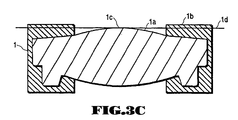
- FIGs. 3A, 3B and 3C show respective objective lenses, of which that shown in Fig 3B is an embodiment of the present invention.
- the upper side of the lens is opposed to the back side of the disc.
- a protective member 1b separate from a lens main body 1a is attached to a peripheral flat surface portion of the lens main body 1a of an objective lens 1 opposed to the back side of the disc.
- This protective member 1b is formed as a ring surrounding the lens main body 1a and is high enough so as to protrude beyond a plane 1d which is tangent to the apex of the convex surface 1c of the lens main body 1a.
- the protective member 1b is preferably formed of an elastic material having a fixed level of hardness, such as rubber, plastic or other suitable materials.
- suitable rubber materials include: natural rubber, butyl, polyurethane VitonTM and other synthetic rubbers.
- suitable plastics include: nylon, Teflon, Delrin, Torlon and polycarbonate.
- other suitable materials include: cotton, paper and other soft materials.
- Fig. 3B the top portion of a protective protrusion 1p of the conventional objective lens 1 is cut away, and the protective member 1b is attached to the surface of the portion of the protective protrusion 1p.
- the protective member 1b protrudes beyond a plane 1d which is tangent to the apex of the convex surface 1c of the lens main body 1a, That is, the protective member 1b is only provided on the protective protrusion 1p surrounding the lens main body 1a.
- the protective protrusion 1p is integrally formed with the objective lens 1.
- the protective member 1b is stacked on top of the protective protrusion 1p.
- the protective member 1b Due to the small working distance between the objective lens 1 and the disk, it is important to minimize the height of the protective member 1b above the apex of the convex surface 1c of the lens main body 1a. If the protective member 1b protrudes to a larger degree than necessary it is liable to collide with the back surface of the disc, which is undesirable. That is, it is undesirable to simply stack the protective member 1b on the protective protrusion 1p well beyond the lens main body 1a since the protective member 1b would forcibly rub against the back surface of the disc. Further, the reproduction of signals would be hindered and the focus mechanism could be damaged since focus servo is constantly operating during the rotation of the disc.
- Fig. 3C illustrates an objective lens 1 wherein the protective member 1b is formed around the perimeter of the objective lens 1.
- the protective member 1b may be molded or attached by other means including: bonding, adhesives and melting around the objective lens 1. Again the protective member 1b protrudes beyond a plane 1d which is tangent to the apex of the convex surface 1c of the lens main body 1a.
- the protective member 1b is formed continuously around the lens main body 1a, it is possible in other embodiments to provide a plurality of protective members 1b at equal intervals or unequal intervals in the periphery of the lens main body 1a.
- the protective protrusion 1p is a plurality of equal intervals or unequal intervals in the periphery of the lens main body 1a.
- the height of the stacked protective member 1b and protective protrusion 1p is the same as the previously described embodiments.
- This protective member 1b may be formed by applying a protective material to the protective protrusion 1p. Because the protective member 1b is made of a soft material, damage to the lens 1 and disc are substantially reduced as compared with objective lenses not having a protective member 1b.
- Figs. 4 and 5 show playback apparatuses for a disc 100 which includes: a laser beam source 10, an aperture, a beam splitter 12, a collimator lens 13, a focusing lens 14, a photodetector 15 and an objective lens 1.
- the laser beam source 10 can be: a laser diode, a semiconductor laser, or the any other suitable laser source.
- the beam splitter 12 separates incident light from the laser beam source 10 and reflected light from the disc 100.
- the collimator lens 13 produces a parallel beam for the objective lens 1.
- the focussing lens 14 focuses light onto the photodetector 15.
- the apparatus shown in Fig. 5 is similar to that shown in Fig. 4 except that in Fig. 5, the incident beam from the laser beam source 10 is transmitted through the beam splitter 12 and the output beam from the disk 100 is reflected by the beam splitter 12.
- the incident beam from the laser beam source 10 is reflected by the beam splitter and the output beam from the disk 100 is transmitted through the beam splitter 12.
- the objective lens 1 has a protective member around the periphery of the lens main body as illustrated in Figs. 3A, 3B and 3C.
- the objective lens of this embodiment is applicable to any system in which a single objective lens is used to read from and/or write to a plurality of kinds of discs, requiring changes in the focal length and working distance.
- an objective lens has a protective member on its surface which protects it from colliding with the associated disc, whereby damage to the lens and disc is avoided.
Landscapes
- Physics & Mathematics (AREA)
- Optics & Photonics (AREA)
- General Physics & Mathematics (AREA)
- Optical Head (AREA)
- Lenses (AREA)
- Window Of Vehicle (AREA)
- Optical Recording Or Reproduction (AREA)
- Glass Compositions (AREA)
- Optical Filters (AREA)
Applications Claiming Priority (3)
| Application Number | Priority Date | Filing Date | Title |
|---|---|---|---|
| JP04240899A JP4136160B2 (ja) | 1999-02-19 | 1999-02-19 | 対物レンズ |
| JP4240899 | 1999-02-19 | ||
| PCT/US2000/004327 WO2000049445A1 (en) | 1999-02-19 | 2000-02-18 | Objective lens |
Publications (4)
| Publication Number | Publication Date |
|---|---|
| EP1161701A1 EP1161701A1 (en) | 2001-12-12 |
| EP1161701A4 EP1161701A4 (en) | 2002-06-12 |
| EP1161701B1 EP1161701B1 (en) | 2005-11-09 |
| EP1161701B9 true EP1161701B9 (en) | 2006-01-18 |
Family
ID=12635252
Family Applications (1)
| Application Number | Title | Priority Date | Filing Date |
|---|---|---|---|
| EP00910251A Expired - Lifetime EP1161701B9 (en) | 1999-02-19 | 2000-02-18 | Objective lens |
Country Status (15)
| Country | Link |
|---|---|
| US (1) | US20020109925A1 (https=) |
| EP (1) | EP1161701B9 (https=) |
| JP (1) | JP4136160B2 (https=) |
| KR (1) | KR20010102271A (https=) |
| CN (1) | CN1156719C (https=) |
| AT (1) | ATE309554T1 (https=) |
| AU (1) | AU3237400A (https=) |
| BR (1) | BR0010115A (https=) |
| CA (1) | CA2362902A1 (https=) |
| DE (1) | DE60023852T2 (https=) |
| HK (1) | HK1041314A1 (https=) |
| MX (1) | MXPA01008393A (https=) |
| NZ (1) | NZ513218A (https=) |
| TW (1) | TW525152B (https=) |
| WO (1) | WO2000049445A1 (https=) |
Families Citing this family (16)
| Publication number | Priority date | Publication date | Assignee | Title |
|---|---|---|---|---|
| US6657944B2 (en) * | 2000-03-01 | 2003-12-02 | Matsushita Electric Industrial Co., Ltd. | Objective lens driving device |
| JP2002072037A (ja) * | 2000-09-01 | 2002-03-12 | Sony Corp | 光学系、光学系の製造方法および光ピックアップ |
| JP4569800B2 (ja) * | 2000-11-22 | 2010-10-27 | ソニー株式会社 | 光学ピックアップ装置及びディスクドライブ装置 |
| DE10216706B9 (de) * | 2002-04-16 | 2007-02-08 | Schott Ag | Verfahren zur Herstellung einer Projektionsscheinwerferlinse |
| CN100373480C (zh) * | 2002-08-05 | 2008-03-05 | 皇家飞利浦电子股份有限公司 | 包括具有透镜保护装置的物镜系统的扫描设备 |
| JP2005149665A (ja) * | 2003-11-19 | 2005-06-09 | Fujitsu Ltd | 光磁気ヘッドおよび光磁気ディスク装置 |
| JP2006004466A (ja) * | 2004-06-15 | 2006-01-05 | Tdk Corp | 対物レンズ、アクチュエータ、光ヘッド及び光記録再生装置 |
| DE102004048500B9 (de) | 2004-10-06 | 2010-03-25 | Schott Ag | Verfahren zur Herstellung einer Projektionsscheinwerferlinse und Werkzeug zum Blankpressen |
| JP2006155825A (ja) * | 2004-11-30 | 2006-06-15 | Sharp Corp | レンズ支持機構、光ピックアップ装置、および、記録再生装置 |
| JPWO2006098361A1 (ja) * | 2005-03-17 | 2008-08-28 | 松下電器産業株式会社 | 光ピックアップ装置および光ディスク装置 |
| US20070033602A1 (en) * | 2005-08-03 | 2007-02-08 | Matsushita Electric Industrial Co., Ltd. | Disk Unit |
| JP2007066433A (ja) * | 2005-08-31 | 2007-03-15 | Canon Inc | 光ディスク装置 |
| WO2007043578A1 (ja) * | 2005-10-14 | 2007-04-19 | Pioneer Corporation | 衝突防止機構及びその製造方法 |
| JP2008130178A (ja) * | 2006-11-22 | 2008-06-05 | Konica Minolta Opto Inc | 光学素子及び光学素子ユニット並びに光学素子製造方法 |
| US8098437B2 (en) | 2010-06-21 | 2012-01-17 | Avago Technologies Fiber Ip (Singapore) Pte. Ltd. | Lens device having protective elements |
| CN106556884A (zh) * | 2015-09-25 | 2017-04-05 | 高准精密工业股份有限公司 | 光学透镜 |
Family Cites Families (7)
| Publication number | Priority date | Publication date | Assignee | Title |
|---|---|---|---|---|
| JPS60179948A (ja) * | 1984-02-27 | 1985-09-13 | Matsushita Electric Ind Co Ltd | 円盤状記録媒体再生用光ピツクアツプ |
| JPH01116196A (ja) * | 1987-10-27 | 1989-05-09 | Mitsui Constr Co Ltd | トンネル用妻止め型枠 |
| JPH0521325U (ja) * | 1991-08-13 | 1993-03-19 | 旭光学工業株式会社 | 光学式情報記録再生装置 |
| JPH0963095A (ja) * | 1995-08-25 | 1997-03-07 | Sony Corp | 光ディスク装置の光学ピックアップ |
| JPH10221583A (ja) * | 1997-02-03 | 1998-08-21 | Matsushita Electric Ind Co Ltd | 光ピックアップ装置 |
| US5995304A (en) * | 1997-07-02 | 1999-11-30 | Fuji Photo Optical Co., Ltd. | Plastic lens |
| JPH1123808A (ja) * | 1997-07-02 | 1999-01-29 | Fuji Photo Optical Co Ltd | プラスチックレンズ |
-
1999
- 1999-02-19 JP JP04240899A patent/JP4136160B2/ja not_active Expired - Fee Related
-
2000
- 2000-02-18 CN CNB008040001A patent/CN1156719C/zh not_active Expired - Lifetime
- 2000-02-18 DE DE60023852T patent/DE60023852T2/de not_active Expired - Lifetime
- 2000-02-18 HK HK02102833.5A patent/HK1041314A1/zh unknown
- 2000-02-18 MX MXPA01008393A patent/MXPA01008393A/es unknown
- 2000-02-18 BR BR0010115-0A patent/BR0010115A/pt not_active Application Discontinuation
- 2000-02-18 TW TW089102882A patent/TW525152B/zh not_active IP Right Cessation
- 2000-02-18 AT AT00910251T patent/ATE309554T1/de not_active IP Right Cessation
- 2000-02-18 CA CA002362902A patent/CA2362902A1/en not_active Abandoned
- 2000-02-18 US US09/507,283 patent/US20020109925A1/en not_active Abandoned
- 2000-02-18 KR KR1020017010573A patent/KR20010102271A/ko not_active Ceased
- 2000-02-18 EP EP00910251A patent/EP1161701B9/en not_active Expired - Lifetime
- 2000-02-18 WO PCT/US2000/004327 patent/WO2000049445A1/en not_active Ceased
- 2000-02-18 AU AU32374/00A patent/AU3237400A/en not_active Abandoned
- 2000-02-18 NZ NZ513218A patent/NZ513218A/xx not_active IP Right Cessation
Also Published As
| Publication number | Publication date |
|---|---|
| CN1341228A (zh) | 2002-03-20 |
| MXPA01008393A (es) | 2003-06-06 |
| DE60023852T2 (de) | 2006-07-27 |
| US20020109925A1 (en) | 2002-08-15 |
| WO2000049445A1 (en) | 2000-08-24 |
| EP1161701B1 (en) | 2005-11-09 |
| JP2000242958A (ja) | 2000-09-08 |
| KR20010102271A (ko) | 2001-11-15 |
| EP1161701A4 (en) | 2002-06-12 |
| ATE309554T1 (de) | 2005-11-15 |
| TW525152B (en) | 2003-03-21 |
| JP4136160B2 (ja) | 2008-08-20 |
| CA2362902A1 (en) | 2000-08-24 |
| NZ513218A (en) | 2002-11-26 |
| BR0010115A (pt) | 2001-12-26 |
| AU3237400A (en) | 2000-09-04 |
| HK1041314A1 (zh) | 2002-07-05 |
| DE60023852D1 (de) | 2005-12-15 |
| CN1156719C (zh) | 2004-07-07 |
| EP1161701A1 (en) | 2001-12-12 |
Similar Documents
| Publication | Publication Date | Title |
|---|---|---|
| EP1161701B9 (en) | Objective lens | |
| US7254098B2 (en) | CD-DVD compatible optical pickup and optical recording and/or reproducing apparatus using the same | |
| KR100656972B1 (ko) | 광학 렌즈와 이것을 사용한 광학 픽업 및 광 디스크 장치 | |
| JP2007328902A (ja) | 対物レンズ装置、光ピックアップ装置、光ディスク駆動装置及び対物レンズの駆動方法 | |
| EP1178474A1 (en) | Optical head | |
| WO2003048834A2 (en) | Optical scanning device | |
| US7133350B2 (en) | Optical pickup and disk drive apparatus | |
| EP1351227B1 (en) | Optical pickup and optical disc drive | |
| KR100675863B1 (ko) | 광픽업장치 | |
| JP4753769B2 (ja) | 対物レンズ保持装置、光ピックアップ装置 | |
| US8161503B2 (en) | Objective lens actuator and an optical pickup | |
| US7102981B2 (en) | Optical scanning device | |
| KR100498472B1 (ko) | 호환형 광픽업 | |
| JP4274285B2 (ja) | 情報ピックアップ装置及び光ディスク装置 | |
| JP5853201B2 (ja) | 光ピックアップおよびドライブ装置 | |
| KR20050030227A (ko) | 렌즈 보호장치를 갖는 대물계를 구비한 주사장치 | |
| JPH10334498A (ja) | 光ピックアップ装置及び光記録再生装置 |
Legal Events
| Date | Code | Title | Description |
|---|---|---|---|
| PUAI | Public reference made under article 153(3) epc to a published international application that has entered the european phase |
Free format text: ORIGINAL CODE: 0009012 |
|
| 17P | Request for examination filed |
Effective date: 20010904 |
|
| AK | Designated contracting states |
Kind code of ref document: A1 Designated state(s): AT BE CH CY DE DK ES FI FR GB GR IE IT LI LU MC NL PT SE |
|
| A4 | Supplementary search report drawn up and despatched |
Effective date: 20020429 |
|
| AK | Designated contracting states |
Kind code of ref document: A4 Designated state(s): AT BE CH CY DE DK ES FI FR GB GR IE IT LI LU MC NL PT SE |
|
| RIC1 | Information provided on ipc code assigned before grant |
Free format text: 7G 02B 17/00 A, 7G 02B 3/02 B, 7G 02B 3/00 B, 7G 02B 1/04 B, 7G 02B 7/02 B |
|
| 17Q | First examination report despatched |
Effective date: 20020725 |
|
| GRAP | Despatch of communication of intention to grant a patent |
Free format text: ORIGINAL CODE: EPIDOSNIGR1 |
|
| GRAS | Grant fee paid |
Free format text: ORIGINAL CODE: EPIDOSNIGR3 |
|
| GRAA | (expected) grant |
Free format text: ORIGINAL CODE: 0009210 |
|
| AK | Designated contracting states |
Kind code of ref document: B1 Designated state(s): AT BE CH CY DE DK ES FI FR GB GR IE IT LI LU MC NL PT SE |
|
| PG25 | Lapsed in a contracting state [announced via postgrant information from national office to epo] |
Ref country code: IT Free format text: LAPSE BECAUSE OF FAILURE TO SUBMIT A TRANSLATION OF THE DESCRIPTION OR TO PAY THE FEE WITHIN THE PRESCRIBED TIME-LIMIT;WARNING: LAPSES OF ITALIAN PATENTS WITH EFFECTIVE DATE BEFORE 2007 MAY HAVE OCCURRED AT ANY TIME BEFORE 2007. THE CORRECT EFFECTIVE DATE MAY BE DIFFERENT FROM THE ONE RECORDED. Effective date: 20051109 Ref country code: FI Free format text: LAPSE BECAUSE OF FAILURE TO SUBMIT A TRANSLATION OF THE DESCRIPTION OR TO PAY THE FEE WITHIN THE PRESCRIBED TIME-LIMIT Effective date: 20051109 Ref country code: LI Free format text: LAPSE BECAUSE OF FAILURE TO SUBMIT A TRANSLATION OF THE DESCRIPTION OR TO PAY THE FEE WITHIN THE PRESCRIBED TIME-LIMIT Effective date: 20051109 Ref country code: BE Free format text: LAPSE BECAUSE OF FAILURE TO SUBMIT A TRANSLATION OF THE DESCRIPTION OR TO PAY THE FEE WITHIN THE PRESCRIBED TIME-LIMIT Effective date: 20051109 Ref country code: AT Free format text: LAPSE BECAUSE OF FAILURE TO SUBMIT A TRANSLATION OF THE DESCRIPTION OR TO PAY THE FEE WITHIN THE PRESCRIBED TIME-LIMIT Effective date: 20051109 Ref country code: NL Free format text: LAPSE BECAUSE OF FAILURE TO SUBMIT A TRANSLATION OF THE DESCRIPTION OR TO PAY THE FEE WITHIN THE PRESCRIBED TIME-LIMIT Effective date: 20051109 Ref country code: CH Free format text: LAPSE BECAUSE OF FAILURE TO SUBMIT A TRANSLATION OF THE DESCRIPTION OR TO PAY THE FEE WITHIN THE PRESCRIBED TIME-LIMIT Effective date: 20051109 |
|
| REG | Reference to a national code |
Ref country code: GB Ref legal event code: FG4D |
|
| REG | Reference to a national code |
Ref country code: CH Ref legal event code: EP |
|
| REG | Reference to a national code |
Ref country code: IE Ref legal event code: FG4D |
|
| REF | Corresponds to: |
Ref document number: 60023852 Country of ref document: DE Date of ref document: 20051215 Kind code of ref document: P |
|
| PG25 | Lapsed in a contracting state [announced via postgrant information from national office to epo] |
Ref country code: SE Free format text: LAPSE BECAUSE OF FAILURE TO SUBMIT A TRANSLATION OF THE DESCRIPTION OR TO PAY THE FEE WITHIN THE PRESCRIBED TIME-LIMIT Effective date: 20060209 Ref country code: DK Free format text: LAPSE BECAUSE OF FAILURE TO SUBMIT A TRANSLATION OF THE DESCRIPTION OR TO PAY THE FEE WITHIN THE PRESCRIBED TIME-LIMIT Effective date: 20060209 Ref country code: GR Free format text: LAPSE BECAUSE OF FAILURE TO SUBMIT A TRANSLATION OF THE DESCRIPTION OR TO PAY THE FEE WITHIN THE PRESCRIBED TIME-LIMIT Effective date: 20060209 |
|
| PG25 | Lapsed in a contracting state [announced via postgrant information from national office to epo] |
Ref country code: IE Free format text: LAPSE BECAUSE OF NON-PAYMENT OF DUE FEES Effective date: 20060220 Ref country code: ES Free format text: LAPSE BECAUSE OF FAILURE TO SUBMIT A TRANSLATION OF THE DESCRIPTION OR TO PAY THE FEE WITHIN THE PRESCRIBED TIME-LIMIT Effective date: 20060220 |
|
| PG25 | Lapsed in a contracting state [announced via postgrant information from national office to epo] |
Ref country code: LU Free format text: LAPSE BECAUSE OF NON-PAYMENT OF DUE FEES Effective date: 20060228 Ref country code: MC Free format text: LAPSE BECAUSE OF NON-PAYMENT OF DUE FEES Effective date: 20060228 |
|
| PG25 | Lapsed in a contracting state [announced via postgrant information from national office to epo] |
Ref country code: PT Free format text: LAPSE BECAUSE OF FAILURE TO SUBMIT A TRANSLATION OF THE DESCRIPTION OR TO PAY THE FEE WITHIN THE PRESCRIBED TIME-LIMIT Effective date: 20060410 |
|
| NLV1 | Nl: lapsed or annulled due to failure to fulfill the requirements of art. 29p and 29m of the patents act | ||
| REG | Reference to a national code |
Ref country code: CH Ref legal event code: PL |
|
| ET | Fr: translation filed | ||
| PLBE | No opposition filed within time limit |
Free format text: ORIGINAL CODE: 0009261 |
|
| STAA | Information on the status of an ep patent application or granted ep patent |
Free format text: STATUS: NO OPPOSITION FILED WITHIN TIME LIMIT |
|
| 26N | No opposition filed |
Effective date: 20060810 |
|
| REG | Reference to a national code |
Ref country code: IE Ref legal event code: MM4A |
|
| REG | Reference to a national code |
Ref country code: HK Ref legal event code: WD Ref document number: 1041314 Country of ref document: HK |
|
| PG25 | Lapsed in a contracting state [announced via postgrant information from national office to epo] |
Ref country code: CY Free format text: LAPSE BECAUSE OF FAILURE TO SUBMIT A TRANSLATION OF THE DESCRIPTION OR TO PAY THE FEE WITHIN THE PRESCRIBED TIME-LIMIT Effective date: 20051109 |
|
| REG | Reference to a national code |
Ref country code: FR Ref legal event code: PLFP Year of fee payment: 17 |
|
| REG | Reference to a national code |
Ref country code: FR Ref legal event code: PLFP Year of fee payment: 18 |
|
| REG | Reference to a national code |
Ref country code: FR Ref legal event code: PLFP Year of fee payment: 19 |
|
| PGFP | Annual fee paid to national office [announced via postgrant information from national office to epo] |
Ref country code: DE Payment date: 20190205 Year of fee payment: 20 Ref country code: FR Payment date: 20190111 Year of fee payment: 20 Ref country code: GB Payment date: 20190213 Year of fee payment: 20 |
|
| REG | Reference to a national code |
Ref country code: DE Ref legal event code: R071 Ref document number: 60023852 Country of ref document: DE |
|
| REG | Reference to a national code |
Ref country code: GB Ref legal event code: PE20 Expiry date: 20200217 |
|
| PG25 | Lapsed in a contracting state [announced via postgrant information from national office to epo] |
Ref country code: GB Free format text: LAPSE BECAUSE OF EXPIRATION OF PROTECTION Effective date: 20200217 |