EP1158233A2 - Schelle zur Befestigung von Schlauch-oder Rohrleitungen - Google Patents
Schelle zur Befestigung von Schlauch-oder Rohrleitungen Download PDFInfo
- Publication number
- EP1158233A2 EP1158233A2 EP01111172A EP01111172A EP1158233A2 EP 1158233 A2 EP1158233 A2 EP 1158233A2 EP 01111172 A EP01111172 A EP 01111172A EP 01111172 A EP01111172 A EP 01111172A EP 1158233 A2 EP1158233 A2 EP 1158233A2
- Authority
- EP
- European Patent Office
- Prior art keywords
- clamp
- parts
- fastening
- eine
- fastening part
- Prior art date
- Legal status (The legal status is an assumption and is not a legal conclusion. Google has not performed a legal analysis and makes no representation as to the accuracy of the status listed.)
- Withdrawn
Links
- 230000000149 penetrating effect Effects 0.000 claims 1
- 238000004873 anchoring Methods 0.000 abstract description 3
- 241000511343 Chondrostoma nasus Species 0.000 abstract 1
- 238000010276 construction Methods 0.000 abstract 1
- 210000001331 nose Anatomy 0.000 description 11
- 239000000463 material Substances 0.000 description 4
- 229910000831 Steel Inorganic materials 0.000 description 3
- 238000004519 manufacturing process Methods 0.000 description 3
- 238000000034 method Methods 0.000 description 3
- 239000010959 steel Substances 0.000 description 3
- 238000006073 displacement reaction Methods 0.000 description 2
- 239000013536 elastomeric material Substances 0.000 description 2
- 208000007101 Muscle Cramp Diseases 0.000 description 1
- 239000000969 carrier Substances 0.000 description 1
- 238000013016 damping Methods 0.000 description 1
- 238000004049 embossing Methods 0.000 description 1
- 238000005516 engineering process Methods 0.000 description 1
- 238000000465 moulding Methods 0.000 description 1
- 229920003051 synthetic elastomer Polymers 0.000 description 1
- 239000005061 synthetic rubber Substances 0.000 description 1
- 239000002023 wood Substances 0.000 description 1
Images

Classifications
-
- F—MECHANICAL ENGINEERING; LIGHTING; HEATING; WEAPONS; BLASTING
- F16—ENGINEERING ELEMENTS AND UNITS; GENERAL MEASURES FOR PRODUCING AND MAINTAINING EFFECTIVE FUNCTIONING OF MACHINES OR INSTALLATIONS; THERMAL INSULATION IN GENERAL
- F16L—PIPES; JOINTS OR FITTINGS FOR PIPES; SUPPORTS FOR PIPES, CABLES OR PROTECTIVE TUBING; MEANS FOR THERMAL INSULATION IN GENERAL
- F16L3/00—Supports for pipes, cables or protective tubing, e.g. hangers, holders, clamps, cleats, clips, brackets
- F16L3/08—Supports for pipes, cables or protective tubing, e.g. hangers, holders, clamps, cleats, clips, brackets substantially surrounding the pipe, cable or protective tubing
- F16L3/10—Supports for pipes, cables or protective tubing, e.g. hangers, holders, clamps, cleats, clips, brackets substantially surrounding the pipe, cable or protective tubing divided, i.e. with two members engaging the pipe, cable or protective tubing
- F16L3/1008—Supports for pipes, cables or protective tubing, e.g. hangers, holders, clamps, cleats, clips, brackets substantially surrounding the pipe, cable or protective tubing divided, i.e. with two members engaging the pipe, cable or protective tubing with two members engaging the pipe, cable or tubing, both being made of thin band material completely surrounding the pipe
-
- F—MECHANICAL ENGINEERING; LIGHTING; HEATING; WEAPONS; BLASTING
- F16—ENGINEERING ELEMENTS AND UNITS; GENERAL MEASURES FOR PRODUCING AND MAINTAINING EFFECTIVE FUNCTIONING OF MACHINES OR INSTALLATIONS; THERMAL INSULATION IN GENERAL
- F16L—PIPES; JOINTS OR FITTINGS FOR PIPES; SUPPORTS FOR PIPES, CABLES OR PROTECTIVE TUBING; MEANS FOR THERMAL INSULATION IN GENERAL
- F16L3/00—Supports for pipes, cables or protective tubing, e.g. hangers, holders, clamps, cleats, clips, brackets
- F16L3/08—Supports for pipes, cables or protective tubing, e.g. hangers, holders, clamps, cleats, clips, brackets substantially surrounding the pipe, cable or protective tubing
- F16L3/10—Supports for pipes, cables or protective tubing, e.g. hangers, holders, clamps, cleats, clips, brackets substantially surrounding the pipe, cable or protective tubing divided, i.e. with two members engaging the pipe, cable or protective tubing
- F16L3/1033—Supports for pipes, cables or protective tubing, e.g. hangers, holders, clamps, cleats, clips, brackets substantially surrounding the pipe, cable or protective tubing divided, i.e. with two members engaging the pipe, cable or protective tubing with two members engaging the pipe, cable or tubing, the two members being joined only on one side of the pipe
-
- F—MECHANICAL ENGINEERING; LIGHTING; HEATING; WEAPONS; BLASTING
- F16—ENGINEERING ELEMENTS AND UNITS; GENERAL MEASURES FOR PRODUCING AND MAINTAINING EFFECTIVE FUNCTIONING OF MACHINES OR INSTALLATIONS; THERMAL INSULATION IN GENERAL
- F16L—PIPES; JOINTS OR FITTINGS FOR PIPES; SUPPORTS FOR PIPES, CABLES OR PROTECTIVE TUBING; MEANS FOR THERMAL INSULATION IN GENERAL
- F16L3/00—Supports for pipes, cables or protective tubing, e.g. hangers, holders, clamps, cleats, clips, brackets
- F16L3/22—Supports for pipes, cables or protective tubing, e.g. hangers, holders, clamps, cleats, clips, brackets specially adapted for supporting a number of parallel pipes at intervals
- F16L3/237—Supports for pipes, cables or protective tubing, e.g. hangers, holders, clamps, cleats, clips, brackets specially adapted for supporting a number of parallel pipes at intervals for two pipes
Definitions
- the invention relates to a clamp for fastening hose or pipelines, with two clamping parts to be fixed on a support, of which each a curved cheek part that is attached to the circumference of the Line interacts, and a flat one, from the cheek part extending fastening part, which for closing the clamp against each other are movable, the jaw parts on their one free End of a safety arrangement against mutual twisting and / or have a joint for opening and closing the clamp.
- Clamps of this type are used in the technology for anchoring cables various types of widespread use. Become a name such clamps with clamping parts made of sheet steel for fastening of hydraulic lines used in excavators. To ensure reliable operation It must be ensured that the relevant lines are anchored be that the clamping parts on their fasteners so together be clamped that twisting of the clamping parts relative to each other, resulting in a pivoting movement of the jaw parts with respect to the axis of the would lead recorded line is safely avoided. To this Purpose is usually more than a clamping screw that the Reach through the fastening parts of the clamping parts to hold the clamping parts against each other to tension and, if necessary, the clamp on a support fasten.
- DE 33 12 865 A1 is a clamp for attaching a corrugated pipe known.
- this known clamp for attaching a corrugated pipe with an overlapping the corrugated pipe, at least over part of one Circle curved section and at least at one end of this section an angled approximately tangentially to the corrugated tube to the outside Section with a hole for the passage of a fastening bolt the section of the clamp overlapping the corrugated pipe points radially inwards protruding projections that can be inserted between the corrugations of the corrugated tube to an axial displacement of the corrugated tube relative to the clamp to prevent.
- the section angled tangentially to the corrugated tube has pointed projections to secure the clamp against rotation by the Projections in the manner of cramps in the carrier on which the clamp is fixed should intervene.
- the known clamp only has one Clamping part, so that the corrugated pipe on a base, for example in Shape of the carrier itself, is to be secured; otherwise it cannot be ruled out that the corrugated tube out of engagement with the curved jaw part of the only clamp part arrives. Furthermore, for the manufacture of Staple connection high engagement forces necessary, using a locking screw are to be applied for the only clamping part.
- the Clamp connection via the pointed projections to secure the rotation Clamp ahead that the material of the carrier is relatively soft, for example in the form of a wood material, is formed to the relevant intervention and to enable the definition in the first place.
- the secure setting the known clamp on steel support parts or the like is therefore not possible.
- German utility model 17 06 079 is a two-part pipe clamp known, both parts on the one hand by means of screw and nut, on the other hand connected by their interlocking ends are.
- the two jaw parts has one end of the clamping part or several recesses into which one or more protrusions of the engage one end of the other clamp member.
- There going pipe clamps are used in particular to fasten tape rolls to their supporting frames and if they were mounted on a fixed support they automatically position themselves in the position during the setting process Carrier change what the assembly process with the known clamp significantly more difficult.
- At least one clamping part at least one from the plane of its fastening part projecting nose is formed, forming an anti-rotation overlaps the carrier laterally or into a designated one Recess of this carrier engages, is a secure anti-rotation reached, provided that the carrier to the corresponding geometries of each projecting nose is adjusted, with little effort and can set the clamp on its clamping parts. Since the respective nose overlaps the carrier or positively in a recess of the wearer, it is also ensured that the flat, fastening part extending away from the cheek part in a flat arrangement the top of the carrier comes, so that a precise connection of Clamp with support is reached. The latter is particularly important if rigid lines with several such clamps over a longer one Distance to be determined on corresponding carriers, where inaccuracies could impair the course of the line.
- the fastening parts of the clamping parts are made with only one Clamping screw tensioned and fixed in this way on the carrier. Since only one Screw is required and in the fastening parts of the clamping parts only a single hole has to be formed, likewise results the benefit of reduced manufacturing costs without sacrificing Operational safety would have to be accepted because the necessary Security against rotation by the positive connection with the carrier of Clamp over the respective nose is guaranteed.
- the anti-rotation device from the plane of the relevant fastening part protruding nose can be easily deformed of a preferably batch of material located on the edge, for example by performing an embossing process.
- the fastening part has a rectangular shape or square plan, is preferably one on each Corner area molded nose provided so that when as a carrier of A suitable, cuboid mounting location is provided for this clamp on two opposite sides by two noses of the adjacent Fastening part is overlapped.
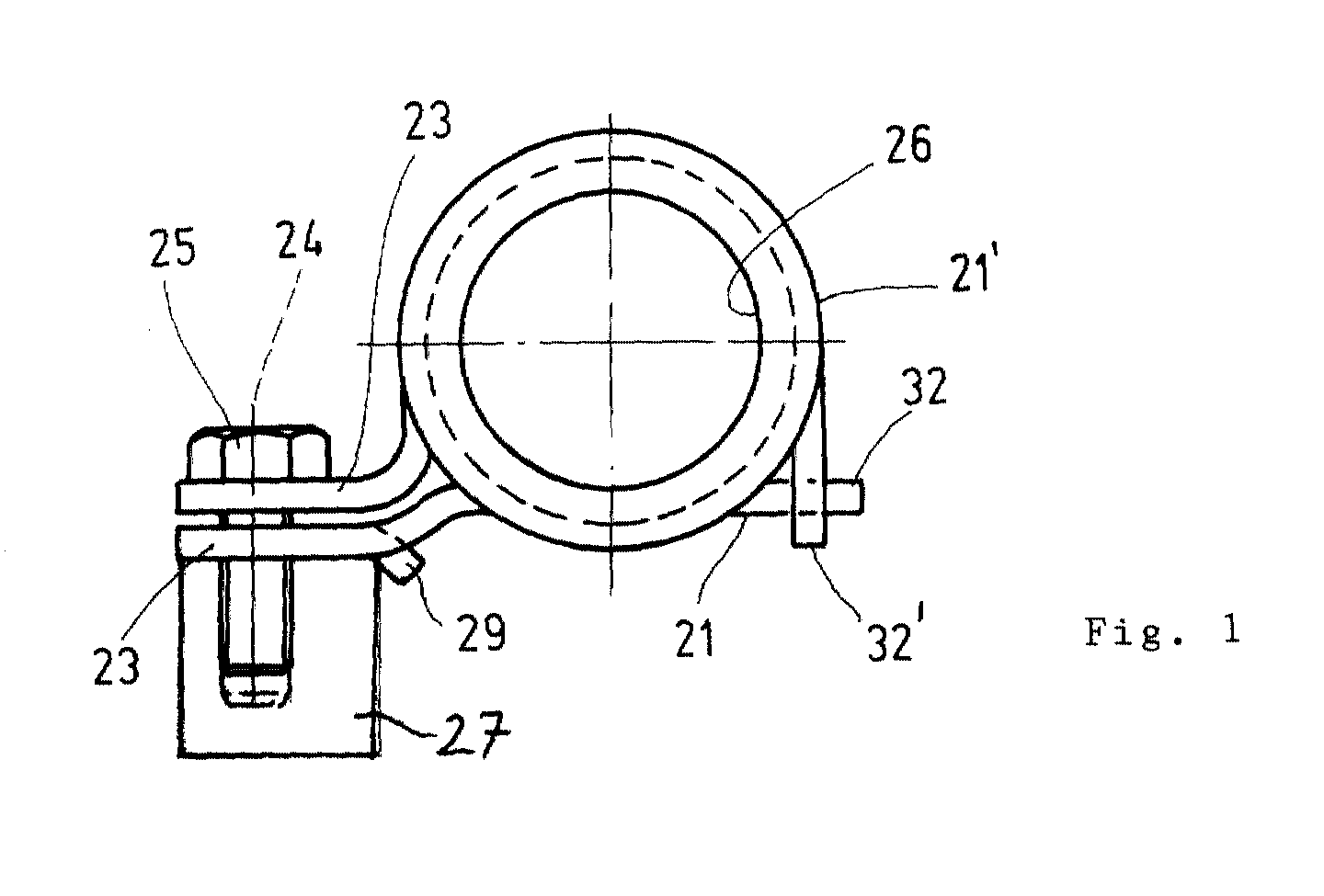
- the figures show a so-called excavator clamp with different designs Clamping parts made of sheet steel, which are shaped so that they each have a curved Jaw part 21, 21 'and a flat part which extends from the jaw part 21, 21' have away extending fastening part 23.
- the square in plan trained flat fastening parts 23 have a centrally located Bore, which is penetrated by a clamping screw 25, through the fastening parts 23 can be clamped against each other and also engages in a threaded bore of a carrier 27, which is a type of mounting block for fixing the clamp on which this is formed by means of the Clamping screw 25 is attached.
- the line to be anchored by means of the clamp (not shown), which between the curved jaw parts 21, 21 'of the clamping parts is received in the embodiment shown in the figures by a split or slotted sleeve 26 made of an elastomeric material.
- the Sleeve 26 has enlarged lateral end edges in diameter, which the Overlap side edges of the jaw parts 21,21 'and the sleeve 26 against Secure axial displacement on these jaw parts 21, 21 '.
- one jaw part 21 ' is U-shaped trained and limited the recording space for each line to be determined.
- the other second jaw part 21 is in contrast formed in the manner of a W structure or wave structure, wherein however, the radii of curvature of the two jaw parts 21, 21 'essentially are the same, provided that the contact areas of the jaw parts 21, 21 ' are addressed with the line to be taken up.
- anti-rotation protection via the molded parts 32, 32 ' the possibility of this via a joint or not shown To replace the hinge point so that this joint or hinge then the clamping parts for the inclusion or release of lines open and close.
Landscapes
- Engineering & Computer Science (AREA)
- General Engineering & Computer Science (AREA)
- Mechanical Engineering (AREA)
- Clamps And Clips (AREA)
- Supports For Pipes And Cables (AREA)
Abstract
Description
Es zeigen die
- Fig.1
- eine Seitenansicht der an einen Träger festgelegten Schelle;
- Fig.2
- eine Draufsicht auf die Schelle nach der Fig.1;
- Fig.3
- eine Seitenansicht der Schelle nach der Fig.2.
Claims (8)
- Schelle zur Befestigung von Schlauch- oder Rohrleitungen, mit zwei an einem Träger (27) festzulegenden Klemmteilen, von denen jedes einen gewölbten Backenteil (21,21'), der mit dem Umfang der zu befestigenden Leitung zusammenwirkt, und einen flachen, sich vom Backenteil (21,21') erstreckenden Befestigungsteil (23) aufweist, die zum Schließen der Schelle gegeneinander bewegbar sind, wobei die Backenteile (21,21') an ihrem einen freien Ende eine Sicherungsanordnung gegen gegenseitiges Verdrehen und/oder eine Gelenkstelle zum Öffnen und Schließen der Schelle aufweisen, dadurch gekennzeichnet, daß an zumindest einem Klemmteil zumindest eine aus der Ebene seines Befestigungsteils (23) vorspringende Nase (29) ausgebildet ist, die unter Bildung einer Verdrehsicherung den Träger (27) seitlich übergreift oder in eine hierfür vorgesehene Ausnehmung dieses Trägers (27) eingreift.
- Schelle nach Anspruch 1, dadurch gekennzeichnet, daß zumindest eine vorspringende Nase (29) durch eine Verformung oder Ausprägung des betreffenden Befestigungsteiles (23) gebildet ist.
- Schelle nach Anspruch 1 oder 2, dadurch gekennzeichnet, daß das Befestigungsteil (23) einen rechteckförmigen oder quadratischen Grundriß aufweist und daß die Befestigungsteile (23) durch eine im Zentralbereich angeordnete, beide Befestigungsteile (23) durchgreifende Klemmschraube (25) am Träger (27) sicherbar sind.
- Schelle nach einem der Ansprüche 1 bis 3, dadurch gekennzeichnet, daß als Träger (27) der Schelle ein quaderförmiger Montageklotz vorgesehen ist, der an einer seiner Seiten durch die Nase (29) des anliegenden Befestigungsteils (23) des Backenteils (21) übergriffen ist oder ein Eingriff dieser Nase (29) an seiner gegenüberliegenden Oberseite zu der Unterseite dieses Befestigungsteils (23) erfolgt.
- Schelle nach einem der Ansprüche 1 bis 4, dadurch gekennzeichnet, daß die Sicherungsanordnung gegen gegenseitiges Verdrehen der beiden Backenteile (21,21') durch Formteile (32,32') gebildet ist, die an den freien Enden der Backenteile (21,21') ausgebildet sind und einen formschlüssigen Eingriff miteinander ermöglichen.
- Schelle nach einem der Ansprüche 1 bis 5, dadurch gekennzeichnet, daß am Befestigungsteil (23) nur eines der Klemmteile eine Nase (29) ausgeformt ist, die in dem dem Backenteil (21) benachbarten Bereich des Befestigungsteils (23) mittig angeordnet und für den Eingriff in eine im Träger (27) ausgebildete Vertiefung vorgesehen ist.
- Schelle nach einem der Ansprüche 1 bis 6, dadurch gekennzeichnet, daß das eine Backenteil (21') U-förmig ausgebildet den Aufnahmeraum für die jeweils festzulegende Leitung begrenzt und daß das weitere zweite Backenteil (21) demgegenüber eine Art W-Struktur oder Wellenstruktur aufweist.
- Schelle nach einem der Ansprüche 1 bis 7, dadurch gekennzeichnet, daß die Krümmungsradien von den beiden Backenteilen (21,21') im wesentlichen gleich sind, sofern die Anlagebereiche der Backenteile (21,21') mit der jeweils aufzunehmenden Leitung angesprochen sind.
Applications Claiming Priority (2)
| Application Number | Priority Date | Filing Date | Title |
|---|---|---|---|
| DE2000123126 DE10023126A1 (de) | 2000-05-11 | 2000-05-11 | Schelle zur Befestigung von Schlauch-oder Rohrleitungen |
| DE10023126 | 2000-05-11 |
Publications (2)
| Publication Number | Publication Date |
|---|---|
| EP1158233A2 true EP1158233A2 (de) | 2001-11-28 |
| EP1158233A3 EP1158233A3 (de) | 2003-04-09 |
Family
ID=7641681
Family Applications (2)
| Application Number | Title | Priority Date | Filing Date |
|---|---|---|---|
| EP01111127A Withdrawn EP1158232A3 (de) | 2000-05-11 | 2001-05-09 | Schelle zur Befestigung von Schlauch- oder Rohrleitungen |
| EP01111172A Withdrawn EP1158233A3 (de) | 2000-05-11 | 2001-05-11 | Schelle zur Befestigung von Schlauch-oder Rohrleitungen |
Family Applications Before (1)
| Application Number | Title | Priority Date | Filing Date |
|---|---|---|---|
| EP01111127A Withdrawn EP1158232A3 (de) | 2000-05-11 | 2001-05-09 | Schelle zur Befestigung von Schlauch- oder Rohrleitungen |
Country Status (2)
| Country | Link |
|---|---|
| EP (2) | EP1158232A3 (de) |
| DE (1) | DE10023126A1 (de) |
Cited By (3)
| Publication number | Priority date | Publication date | Assignee | Title |
|---|---|---|---|---|
| WO2007141074A1 (de) * | 2006-06-02 | 2007-12-13 | Contitech Techno-Chemie Gmbh | Halterung für eine rohrleitung |
| EP3032154A1 (de) | 2014-12-12 | 2016-06-15 | Bombardier Transportation GmbH | Schelle zur befestigung einer leitung, insbesondere stromführenden leitung, an einem schienenfahrzeug |
| USD950369S1 (en) | 2017-05-22 | 2022-05-03 | Erico International Corporation | Pipe clamp |
Families Citing this family (4)
| Publication number | Priority date | Publication date | Assignee | Title |
|---|---|---|---|---|
| DE102006003448B3 (de) * | 2006-01-25 | 2007-04-05 | Daimlerchrysler Ag | Befestigungsanordnung zur Anbringung einer Leitung an einem Kraftfahrzeug |
| DE102008045914B4 (de) | 2008-08-28 | 2018-01-11 | Progress-Werk Oberkirch Ag | Querträger für ein Kraftfahrzeug |
| DE102009023613A1 (de) | 2009-06-02 | 2010-01-21 | Daimler Ag | Schelle zur Befestigung von zumindest einer Schlauch- und/oder Rohrleitung und/oder eines Kabels |
| DE102013212116A1 (de) * | 2013-06-25 | 2015-01-08 | Mahle International Gmbh | Turbolader und Verbindungselement |
Family Cites Families (11)
| Publication number | Priority date | Publication date | Assignee | Title |
|---|---|---|---|---|
| AT20893B (de) * | 1904-09-28 | 1905-08-10 | Luis De Bertolini | Rohrschelle. |
| GB239390A (en) * | 1924-10-24 | 1925-09-10 | Arthur Henry Barker | Improved means for attaching pipes to walls |
| DE1706079U (de) * | 1954-11-08 | 1955-09-01 | Miag Muehlenbau & Ind Gmbh | Zweiteilige rohrschelle. |
| DE1868116U (de) * | 1962-12-18 | 1963-02-28 | Anton Kathrein Aelteste Spezia | Rohrbefestigungsschelle. |
| US3559933A (en) * | 1969-02-28 | 1971-02-02 | Thomas & Betts Corp | Conduit mounting device |
| FR2233880A5 (en) * | 1973-06-15 | 1975-01-10 | Fuchs Charles | Support for fixing pipes to walls etc. - two half collars are clamped round pipe and a mounting bolt |
| DE2907850C2 (de) * | 1979-02-28 | 1980-09-18 | Hubert 1000 Berlin Combe | Rohrschelle |
| DE3312865A1 (de) * | 1983-04-09 | 1984-10-18 | Rasmussen Gmbh, 6457 Maintal | Schelle zum befestigen eines wellrohres |
| JPH08135850A (ja) * | 1994-11-04 | 1996-05-31 | Shin Caterpillar Mitsubishi Ltd | 配管用ストラップ |
| JPH08135534A (ja) * | 1994-11-04 | 1996-05-28 | Suzuki Motor Corp | 内燃機関の吸気装置 |
| JP2844062B2 (ja) * | 1996-11-22 | 1999-01-06 | 日栄インテック株式会社 | 単一箇所締着用立バンド |
-
2000
- 2000-05-11 DE DE2000123126 patent/DE10023126A1/de not_active Ceased
-
2001
- 2001-05-09 EP EP01111127A patent/EP1158232A3/de not_active Withdrawn
- 2001-05-11 EP EP01111172A patent/EP1158233A3/de not_active Withdrawn
Cited By (6)
| Publication number | Priority date | Publication date | Assignee | Title |
|---|---|---|---|---|
| WO2007141074A1 (de) * | 2006-06-02 | 2007-12-13 | Contitech Techno-Chemie Gmbh | Halterung für eine rohrleitung |
| US7959114B2 (en) | 2006-06-02 | 2011-06-14 | Contitech Techno-Chemie Gmbh | Holder for a pipeline |
| EP3032154A1 (de) | 2014-12-12 | 2016-06-15 | Bombardier Transportation GmbH | Schelle zur befestigung einer leitung, insbesondere stromführenden leitung, an einem schienenfahrzeug |
| DE102014118499A1 (de) | 2014-12-12 | 2016-06-16 | Bombardier Transportation Gmbh | Schelle zur Befestigung einer Leitung, insbesondere stromführenden Leitung, an einem Schienenfahrzeug |
| DE102014118499B4 (de) * | 2014-12-12 | 2021-03-25 | Bombardier Transportation Gmbh | Schelle zur Befestigung einer Leitung, insbesondere stromführenden Leitung, an einem Schienenfahrzeug |
| USD950369S1 (en) | 2017-05-22 | 2022-05-03 | Erico International Corporation | Pipe clamp |
Also Published As
| Publication number | Publication date |
|---|---|
| EP1158233A3 (de) | 2003-04-09 |
| EP1158232A2 (de) | 2001-11-28 |
| DE10023126A1 (de) | 2001-11-29 |
| EP1158232A3 (de) | 2003-04-09 |
Similar Documents
| Publication | Publication Date | Title |
|---|---|---|
| DE3872974T2 (de) | Geschichteter splint oder verriegelungsklammer und kupplungen und verbindungen damit. | |
| DE60015970T2 (de) | Metall-kunststoff-klammer zum befestigen von fahrzeugdächern und zubehör an der karosserie eines fahrzeuges | |
| DE3532170A1 (de) | Vorrichtung zum tragen einer last | |
| EP0508050A2 (de) | Gelenkband-Konsolenschelle | |
| DE10026020B4 (de) | Schneckengewindeschelle | |
| DE8806714U1 (de) | Befestigungsbügel | |
| DE3420986A1 (de) | Laengliches formteil zur anordnung zwischen einem am kotfluegelfalz eines kraftfahrzeugs befestigten schmutzfaengerlappen und dem kotfluegelfalz | |
| DE69401399T2 (de) | Rohrschelle | |
| DE10236553A1 (de) | Winkelelement | |
| DE69217445T2 (de) | Klemmschelle | |
| DE2543897C3 (de) | Vorrichtung zum Halten eines rohrförmigen Handlaufs | |
| EP1158233A2 (de) | Schelle zur Befestigung von Schlauch-oder Rohrleitungen | |
| DE4409765C2 (de) | Rohrbefestigungsvorrichtung | |
| DE2620522C3 (de) | Klemmvorrichtung für einen Schalungszuganker | |
| WO2011012191A1 (de) | Bandschelle | |
| WO1996041979A1 (de) | Vorrichtung zur abdichtung zwischen beweglichen anlagenteilen | |
| DE29713845U1 (de) | Preßfitting für Kunststoffrohre, insbesondere Kunststoff-Metall-Verbundrohre | |
| DE4210280C1 (de) | Leitungswagen für Elektrokabel | |
| EP0315811B1 (de) | Halter zur Befestigung einer Mauerabdeckung | |
| DE112007001491T5 (de) | Lastträgerfuß zum Befestigen eines Lastträgers an einem Fahrzeugdach | |
| EP0233972B1 (de) | Thermoplastspannring | |
| DE3407327A1 (de) | Anordnung zur halterung von im bereich eines drehgelenkes eines gelenkzuges, insbesondere eines gelenkomnibusses, angeordneten flexiblen verbindungsleitungen | |
| DE3500969A1 (de) | Abdeckplatte zum abdecken des bodens im bereich von aus dem boden herausragenden halterungen, pfaehlen u.a. | |
| EP1561877A2 (de) | Verbindungsvorrichtung | |
| DE4328107C1 (de) | Haltebacke für eine Rohrhalterung |
Legal Events
| Date | Code | Title | Description |
|---|---|---|---|
| PUAI | Public reference made under article 153(3) epc to a published international application that has entered the european phase |
Free format text: ORIGINAL CODE: 0009012 |
|
| AK | Designated contracting states |
Kind code of ref document: A2 Designated state(s): AT BE CH CY DE DK ES FI FR GB GR IE IT LI LU MC NL PT SE TR |
|
| AX | Request for extension of the european patent |
Free format text: AL;LT;LV;MK;RO;SI |
|
| PUAL | Search report despatched |
Free format text: ORIGINAL CODE: 0009013 |
|
| AK | Designated contracting states |
Kind code of ref document: A3 Designated state(s): AT BE CH CY DE DK ES FI FR GB GR IE IT LI LU MC NL PT SE TR Designated state(s): AT BE CH CY DE DK ES FI FR GB GR IE IT LI LU MC NL PT SE TR |
|
| AX | Request for extension of the european patent |
Extension state: AL LT LV MK RO SI |
|
| RIC1 | Information provided on ipc code assigned before grant |
Ipc: 7F 16L 3/237 B Ipc: 7F 16L 3/10 A |
|
| RAP1 | Party data changed (applicant data changed or rights of an application transferred) |
Owner name: HYDAC ACCESSORIES GMBH |
|
| 17P | Request for examination filed |
Effective date: 20030522 |
|
| 17Q | First examination report despatched |
Effective date: 20030828 |
|
| AKX | Designation fees paid |
Designated state(s): AT DE FR GB IT SE |
|
| GRAP | Despatch of communication of intention to grant a patent |
Free format text: ORIGINAL CODE: EPIDOSNIGR1 |
|
| STAA | Information on the status of an ep patent application or granted ep patent |
Free format text: STATUS: THE APPLICATION IS DEEMED TO BE WITHDRAWN |
|
| 18D | Application deemed to be withdrawn |
Effective date: 20040629 |