EP1158143B1 - Dispositif de purification des gaz d'échappement d'un moteur diesel - Google Patents
Dispositif de purification des gaz d'échappement d'un moteur diesel Download PDFInfo
- Publication number
- EP1158143B1 EP1158143B1 EP01119165A EP01119165A EP1158143B1 EP 1158143 B1 EP1158143 B1 EP 1158143B1 EP 01119165 A EP01119165 A EP 01119165A EP 01119165 A EP01119165 A EP 01119165A EP 1158143 B1 EP1158143 B1 EP 1158143B1
- Authority
- EP
- European Patent Office
- Prior art keywords
- diesel fuel
- filter
- exhaust gas
- engine
- oxidation catalyst
- Prior art date
- Legal status (The legal status is an assumption and is not a legal conclusion. Google has not performed a legal analysis and makes no representation as to the accuracy of the status listed.)
- Expired - Lifetime
Links
Images


Classifications
-
- F—MECHANICAL ENGINEERING; LIGHTING; HEATING; WEAPONS; BLASTING
- F01—MACHINES OR ENGINES IN GENERAL; ENGINE PLANTS IN GENERAL; STEAM ENGINES
- F01N—GAS-FLOW SILENCERS OR EXHAUST APPARATUS FOR MACHINES OR ENGINES IN GENERAL; GAS-FLOW SILENCERS OR EXHAUST APPARATUS FOR INTERNAL COMBUSTION ENGINES
- F01N9/00—Electrical control of exhaust gas treating apparatus
- F01N9/002—Electrical control of exhaust gas treating apparatus of filter regeneration, e.g. detection of clogging
-
- B—PERFORMING OPERATIONS; TRANSPORTING
- B01—PHYSICAL OR CHEMICAL PROCESSES OR APPARATUS IN GENERAL
- B01D—SEPARATION
- B01D53/00—Separation of gases or vapours; Recovering vapours of volatile solvents from gases; Chemical or biological purification of waste gases, e.g. engine exhaust gases, smoke, fumes, flue gases, aerosols
- B01D53/34—Chemical or biological purification of waste gases
- B01D53/92—Chemical or biological purification of waste gases of engine exhaust gases
- B01D53/94—Chemical or biological purification of waste gases of engine exhaust gases by catalytic processes
- B01D53/9481—Catalyst preceded by an adsorption device without catalytic function for temporary storage of contaminants, e.g. during cold start
-
- B—PERFORMING OPERATIONS; TRANSPORTING
- B01—PHYSICAL OR CHEMICAL PROCESSES OR APPARATUS IN GENERAL
- B01D—SEPARATION
- B01D53/00—Separation of gases or vapours; Recovering vapours of volatile solvents from gases; Chemical or biological purification of waste gases, e.g. engine exhaust gases, smoke, fumes, flue gases, aerosols
- B01D53/34—Chemical or biological purification of waste gases
- B01D53/92—Chemical or biological purification of waste gases of engine exhaust gases
- B01D53/94—Chemical or biological purification of waste gases of engine exhaust gases by catalytic processes
- B01D53/9495—Controlling the catalytic process
-
- F—MECHANICAL ENGINEERING; LIGHTING; HEATING; WEAPONS; BLASTING
- F01—MACHINES OR ENGINES IN GENERAL; ENGINE PLANTS IN GENERAL; STEAM ENGINES
- F01N—GAS-FLOW SILENCERS OR EXHAUST APPARATUS FOR MACHINES OR ENGINES IN GENERAL; GAS-FLOW SILENCERS OR EXHAUST APPARATUS FOR INTERNAL COMBUSTION ENGINES
- F01N13/00—Exhaust or silencing apparatus characterised by constructional features ; Exhaust or silencing apparatus, or parts thereof, having pertinent characteristics not provided for in, or of interest apart from, groups F01N1/00 - F01N5/00, F01N9/00, F01N11/00
- F01N13/009—Exhaust or silencing apparatus characterised by constructional features ; Exhaust or silencing apparatus, or parts thereof, having pertinent characteristics not provided for in, or of interest apart from, groups F01N1/00 - F01N5/00, F01N9/00, F01N11/00 having two or more separate purifying devices arranged in series
-
- F—MECHANICAL ENGINEERING; LIGHTING; HEATING; WEAPONS; BLASTING
- F01—MACHINES OR ENGINES IN GENERAL; ENGINE PLANTS IN GENERAL; STEAM ENGINES
- F01N—GAS-FLOW SILENCERS OR EXHAUST APPARATUS FOR MACHINES OR ENGINES IN GENERAL; GAS-FLOW SILENCERS OR EXHAUST APPARATUS FOR INTERNAL COMBUSTION ENGINES
- F01N3/00—Exhaust or silencing apparatus having means for purifying, rendering innocuous, or otherwise treating exhaust
- F01N3/02—Exhaust or silencing apparatus having means for purifying, rendering innocuous, or otherwise treating exhaust for cooling, or for removing solid constituents of, exhaust
- F01N3/021—Exhaust or silencing apparatus having means for purifying, rendering innocuous, or otherwise treating exhaust for cooling, or for removing solid constituents of, exhaust by means of filters
- F01N3/023—Exhaust or silencing apparatus having means for purifying, rendering innocuous, or otherwise treating exhaust for cooling, or for removing solid constituents of, exhaust by means of filters using means for regenerating the filters, e.g. by burning trapped particles
- F01N3/025—Exhaust or silencing apparatus having means for purifying, rendering innocuous, or otherwise treating exhaust for cooling, or for removing solid constituents of, exhaust by means of filters using means for regenerating the filters, e.g. by burning trapped particles using fuel burner or by adding fuel to exhaust
- F01N3/0253—Exhaust or silencing apparatus having means for purifying, rendering innocuous, or otherwise treating exhaust for cooling, or for removing solid constituents of, exhaust by means of filters using means for regenerating the filters, e.g. by burning trapped particles using fuel burner or by adding fuel to exhaust adding fuel to exhaust gases
-
- F—MECHANICAL ENGINEERING; LIGHTING; HEATING; WEAPONS; BLASTING
- F01—MACHINES OR ENGINES IN GENERAL; ENGINE PLANTS IN GENERAL; STEAM ENGINES
- F01N—GAS-FLOW SILENCERS OR EXHAUST APPARATUS FOR MACHINES OR ENGINES IN GENERAL; GAS-FLOW SILENCERS OR EXHAUST APPARATUS FOR INTERNAL COMBUSTION ENGINES
- F01N3/00—Exhaust or silencing apparatus having means for purifying, rendering innocuous, or otherwise treating exhaust
- F01N3/08—Exhaust or silencing apparatus having means for purifying, rendering innocuous, or otherwise treating exhaust for rendering innocuous
- F01N3/0807—Exhaust or silencing apparatus having means for purifying, rendering innocuous, or otherwise treating exhaust for rendering innocuous by using absorbents or adsorbents
- F01N3/0821—Exhaust or silencing apparatus having means for purifying, rendering innocuous, or otherwise treating exhaust for rendering innocuous by using absorbents or adsorbents combined with particulate filters
-
- F—MECHANICAL ENGINEERING; LIGHTING; HEATING; WEAPONS; BLASTING
- F01—MACHINES OR ENGINES IN GENERAL; ENGINE PLANTS IN GENERAL; STEAM ENGINES
- F01N—GAS-FLOW SILENCERS OR EXHAUST APPARATUS FOR MACHINES OR ENGINES IN GENERAL; GAS-FLOW SILENCERS OR EXHAUST APPARATUS FOR INTERNAL COMBUSTION ENGINES
- F01N3/00—Exhaust or silencing apparatus having means for purifying, rendering innocuous, or otherwise treating exhaust
- F01N3/08—Exhaust or silencing apparatus having means for purifying, rendering innocuous, or otherwise treating exhaust for rendering innocuous
- F01N3/0807—Exhaust or silencing apparatus having means for purifying, rendering innocuous, or otherwise treating exhaust for rendering innocuous by using absorbents or adsorbents
- F01N3/0828—Exhaust or silencing apparatus having means for purifying, rendering innocuous, or otherwise treating exhaust for rendering innocuous by using absorbents or adsorbents characterised by the absorbed or adsorbed substances
- F01N3/0835—Hydrocarbons
-
- F—MECHANICAL ENGINEERING; LIGHTING; HEATING; WEAPONS; BLASTING
- F01—MACHINES OR ENGINES IN GENERAL; ENGINE PLANTS IN GENERAL; STEAM ENGINES
- F01N—GAS-FLOW SILENCERS OR EXHAUST APPARATUS FOR MACHINES OR ENGINES IN GENERAL; GAS-FLOW SILENCERS OR EXHAUST APPARATUS FOR INTERNAL COMBUSTION ENGINES
- F01N3/00—Exhaust or silencing apparatus having means for purifying, rendering innocuous, or otherwise treating exhaust
- F01N3/08—Exhaust or silencing apparatus having means for purifying, rendering innocuous, or otherwise treating exhaust for rendering innocuous
- F01N3/0807—Exhaust or silencing apparatus having means for purifying, rendering innocuous, or otherwise treating exhaust for rendering innocuous by using absorbents or adsorbents
- F01N3/0871—Regulation of absorbents or adsorbents, e.g. purging
-
- F—MECHANICAL ENGINEERING; LIGHTING; HEATING; WEAPONS; BLASTING
- F01—MACHINES OR ENGINES IN GENERAL; ENGINE PLANTS IN GENERAL; STEAM ENGINES
- F01N—GAS-FLOW SILENCERS OR EXHAUST APPARATUS FOR MACHINES OR ENGINES IN GENERAL; GAS-FLOW SILENCERS OR EXHAUST APPARATUS FOR INTERNAL COMBUSTION ENGINES
- F01N3/00—Exhaust or silencing apparatus having means for purifying, rendering innocuous, or otherwise treating exhaust
- F01N3/08—Exhaust or silencing apparatus having means for purifying, rendering innocuous, or otherwise treating exhaust for rendering innocuous
- F01N3/10—Exhaust or silencing apparatus having means for purifying, rendering innocuous, or otherwise treating exhaust for rendering innocuous by thermal or catalytic conversion of noxious components of exhaust
- F01N3/18—Exhaust or silencing apparatus having means for purifying, rendering innocuous, or otherwise treating exhaust for rendering innocuous by thermal or catalytic conversion of noxious components of exhaust characterised by methods of operation; Control
- F01N3/20—Exhaust or silencing apparatus having means for purifying, rendering innocuous, or otherwise treating exhaust for rendering innocuous by thermal or catalytic conversion of noxious components of exhaust characterised by methods of operation; Control specially adapted for catalytic conversion ; Methods of operation or control of catalytic converters
- F01N3/2006—Periodically heating or cooling catalytic reactors, e.g. at cold starting or overheating
- F01N3/2033—Periodically heating or cooling catalytic reactors, e.g. at cold starting or overheating using a fuel burner or introducing fuel into exhaust duct
-
- F—MECHANICAL ENGINEERING; LIGHTING; HEATING; WEAPONS; BLASTING
- F01—MACHINES OR ENGINES IN GENERAL; ENGINE PLANTS IN GENERAL; STEAM ENGINES
- F01N—GAS-FLOW SILENCERS OR EXHAUST APPARATUS FOR MACHINES OR ENGINES IN GENERAL; GAS-FLOW SILENCERS OR EXHAUST APPARATUS FOR INTERNAL COMBUSTION ENGINES
- F01N3/00—Exhaust or silencing apparatus having means for purifying, rendering innocuous, or otherwise treating exhaust
- F01N3/08—Exhaust or silencing apparatus having means for purifying, rendering innocuous, or otherwise treating exhaust for rendering innocuous
- F01N3/10—Exhaust or silencing apparatus having means for purifying, rendering innocuous, or otherwise treating exhaust for rendering innocuous by thermal or catalytic conversion of noxious components of exhaust
- F01N3/24—Exhaust or silencing apparatus having means for purifying, rendering innocuous, or otherwise treating exhaust for rendering innocuous by thermal or catalytic conversion of noxious components of exhaust characterised by constructional aspects of converting apparatus
- F01N3/36—Arrangements for supply of additional fuel
-
- F—MECHANICAL ENGINEERING; LIGHTING; HEATING; WEAPONS; BLASTING
- F01—MACHINES OR ENGINES IN GENERAL; ENGINE PLANTS IN GENERAL; STEAM ENGINES
- F01N—GAS-FLOW SILENCERS OR EXHAUST APPARATUS FOR MACHINES OR ENGINES IN GENERAL; GAS-FLOW SILENCERS OR EXHAUST APPARATUS FOR INTERNAL COMBUSTION ENGINES
- F01N9/00—Electrical control of exhaust gas treating apparatus
-
- F—MECHANICAL ENGINEERING; LIGHTING; HEATING; WEAPONS; BLASTING
- F01—MACHINES OR ENGINES IN GENERAL; ENGINE PLANTS IN GENERAL; STEAM ENGINES
- F01N—GAS-FLOW SILENCERS OR EXHAUST APPARATUS FOR MACHINES OR ENGINES IN GENERAL; GAS-FLOW SILENCERS OR EXHAUST APPARATUS FOR INTERNAL COMBUSTION ENGINES
- F01N2240/00—Combination or association of two or more different exhaust treating devices, or of at least one such device with an auxiliary device, not covered by indexing codes F01N2230/00 or F01N2250/00, one of the devices being
- F01N2240/16—Combination or association of two or more different exhaust treating devices, or of at least one such device with an auxiliary device, not covered by indexing codes F01N2230/00 or F01N2250/00, one of the devices being an electric heater, i.e. a resistance heater
-
- F—MECHANICAL ENGINEERING; LIGHTING; HEATING; WEAPONS; BLASTING
- F01—MACHINES OR ENGINES IN GENERAL; ENGINE PLANTS IN GENERAL; STEAM ENGINES
- F01N—GAS-FLOW SILENCERS OR EXHAUST APPARATUS FOR MACHINES OR ENGINES IN GENERAL; GAS-FLOW SILENCERS OR EXHAUST APPARATUS FOR INTERNAL COMBUSTION ENGINES
- F01N2250/00—Combinations of different methods of purification
- F01N2250/12—Combinations of different methods of purification absorption or adsorption, and catalytic conversion
-
- F—MECHANICAL ENGINEERING; LIGHTING; HEATING; WEAPONS; BLASTING
- F01—MACHINES OR ENGINES IN GENERAL; ENGINE PLANTS IN GENERAL; STEAM ENGINES
- F01N—GAS-FLOW SILENCERS OR EXHAUST APPARATUS FOR MACHINES OR ENGINES IN GENERAL; GAS-FLOW SILENCERS OR EXHAUST APPARATUS FOR INTERNAL COMBUSTION ENGINES
- F01N2250/00—Combinations of different methods of purification
- F01N2250/14—Combinations of different methods of purification absorption or adsorption, and filtering
-
- F—MECHANICAL ENGINEERING; LIGHTING; HEATING; WEAPONS; BLASTING
- F01—MACHINES OR ENGINES IN GENERAL; ENGINE PLANTS IN GENERAL; STEAM ENGINES
- F01N—GAS-FLOW SILENCERS OR EXHAUST APPARATUS FOR MACHINES OR ENGINES IN GENERAL; GAS-FLOW SILENCERS OR EXHAUST APPARATUS FOR INTERNAL COMBUSTION ENGINES
- F01N2430/00—Influencing exhaust purification, e.g. starting of catalytic reaction, filter regeneration, or the like, by controlling engine operating characteristics
- F01N2430/06—Influencing exhaust purification, e.g. starting of catalytic reaction, filter regeneration, or the like, by controlling engine operating characteristics by varying fuel-air ratio, e.g. by enriching fuel-air mixture
-
- F—MECHANICAL ENGINEERING; LIGHTING; HEATING; WEAPONS; BLASTING
- F01—MACHINES OR ENGINES IN GENERAL; ENGINE PLANTS IN GENERAL; STEAM ENGINES
- F01N—GAS-FLOW SILENCERS OR EXHAUST APPARATUS FOR MACHINES OR ENGINES IN GENERAL; GAS-FLOW SILENCERS OR EXHAUST APPARATUS FOR INTERNAL COMBUSTION ENGINES
- F01N2560/00—Exhaust systems with means for detecting or measuring exhaust gas components or characteristics
- F01N2560/02—Exhaust systems with means for detecting or measuring exhaust gas components or characteristics the means being an exhaust gas sensor
- F01N2560/026—Exhaust systems with means for detecting or measuring exhaust gas components or characteristics the means being an exhaust gas sensor for measuring or detecting NOx
-
- F—MECHANICAL ENGINEERING; LIGHTING; HEATING; WEAPONS; BLASTING
- F01—MACHINES OR ENGINES IN GENERAL; ENGINE PLANTS IN GENERAL; STEAM ENGINES
- F01N—GAS-FLOW SILENCERS OR EXHAUST APPARATUS FOR MACHINES OR ENGINES IN GENERAL; GAS-FLOW SILENCERS OR EXHAUST APPARATUS FOR INTERNAL COMBUSTION ENGINES
- F01N2610/00—Adding substances to exhaust gases
- F01N2610/03—Adding substances to exhaust gases the substance being hydrocarbons, e.g. engine fuel
-
- F—MECHANICAL ENGINEERING; LIGHTING; HEATING; WEAPONS; BLASTING
- F01—MACHINES OR ENGINES IN GENERAL; ENGINE PLANTS IN GENERAL; STEAM ENGINES
- F01N—GAS-FLOW SILENCERS OR EXHAUST APPARATUS FOR MACHINES OR ENGINES IN GENERAL; GAS-FLOW SILENCERS OR EXHAUST APPARATUS FOR INTERNAL COMBUSTION ENGINES
- F01N2610/00—Adding substances to exhaust gases
- F01N2610/10—Adding substances to exhaust gases the substance being heated, e.g. by heating tank or supply line of the added substance
-
- F—MECHANICAL ENGINEERING; LIGHTING; HEATING; WEAPONS; BLASTING
- F01—MACHINES OR ENGINES IN GENERAL; ENGINE PLANTS IN GENERAL; STEAM ENGINES
- F01N—GAS-FLOW SILENCERS OR EXHAUST APPARATUS FOR MACHINES OR ENGINES IN GENERAL; GAS-FLOW SILENCERS OR EXHAUST APPARATUS FOR INTERNAL COMBUSTION ENGINES
- F01N2610/00—Adding substances to exhaust gases
- F01N2610/14—Arrangements for the supply of substances, e.g. conduits
-
- F—MECHANICAL ENGINEERING; LIGHTING; HEATING; WEAPONS; BLASTING
- F02—COMBUSTION ENGINES; HOT-GAS OR COMBUSTION-PRODUCT ENGINE PLANTS
- F02B—INTERNAL-COMBUSTION PISTON ENGINES; COMBUSTION ENGINES IN GENERAL
- F02B3/00—Engines characterised by air compression and subsequent fuel addition
- F02B3/06—Engines characterised by air compression and subsequent fuel addition with compression ignition
-
- F—MECHANICAL ENGINEERING; LIGHTING; HEATING; WEAPONS; BLASTING
- F02—COMBUSTION ENGINES; HOT-GAS OR COMBUSTION-PRODUCT ENGINE PLANTS
- F02D—CONTROLLING COMBUSTION ENGINES
- F02D41/00—Electrical control of supply of combustible mixture or its constituents
- F02D41/0025—Controlling engines characterised by use of non-liquid fuels, pluralities of fuels, or non-fuel substances added to the combustible mixtures
- F02D41/0047—Controlling exhaust gas recirculation [EGR]
- F02D41/005—Controlling exhaust gas recirculation [EGR] according to engine operating conditions
- F02D41/0055—Special engine operating conditions, e.g. for regeneration of exhaust gas treatment apparatus
-
- F—MECHANICAL ENGINEERING; LIGHTING; HEATING; WEAPONS; BLASTING
- F02—COMBUSTION ENGINES; HOT-GAS OR COMBUSTION-PRODUCT ENGINE PLANTS
- F02D—CONTROLLING COMBUSTION ENGINES
- F02D41/00—Electrical control of supply of combustible mixture or its constituents
- F02D41/02—Circuit arrangements for generating control signals
- F02D41/021—Introducing corrections for particular conditions exterior to the engine
- F02D41/0235—Introducing corrections for particular conditions exterior to the engine in relation with the state of the exhaust gas treating apparatus
- F02D41/027—Introducing corrections for particular conditions exterior to the engine in relation with the state of the exhaust gas treating apparatus to purge or regenerate the exhaust gas treating apparatus
- F02D41/029—Introducing corrections for particular conditions exterior to the engine in relation with the state of the exhaust gas treating apparatus to purge or regenerate the exhaust gas treating apparatus the exhaust gas treating apparatus being a particulate filter
-
- F—MECHANICAL ENGINEERING; LIGHTING; HEATING; WEAPONS; BLASTING
- F02—COMBUSTION ENGINES; HOT-GAS OR COMBUSTION-PRODUCT ENGINE PLANTS
- F02M—SUPPLYING COMBUSTION ENGINES IN GENERAL WITH COMBUSTIBLE MIXTURES OR CONSTITUENTS THEREOF
- F02M26/00—Engine-pertinent apparatus for adding exhaust gases to combustion-air, main fuel or fuel-air mixture, e.g. by exhaust gas recirculation [EGR] systems
- F02M26/13—Arrangement or layout of EGR passages, e.g. in relation to specific engine parts or for incorporation of accessories
- F02M26/14—Arrangement or layout of EGR passages, e.g. in relation to specific engine parts or for incorporation of accessories in relation to the exhaust system
- F02M26/15—Arrangement or layout of EGR passages, e.g. in relation to specific engine parts or for incorporation of accessories in relation to the exhaust system in relation to engine exhaust purifying apparatus
-
- Y—GENERAL TAGGING OF NEW TECHNOLOGICAL DEVELOPMENTS; GENERAL TAGGING OF CROSS-SECTIONAL TECHNOLOGIES SPANNING OVER SEVERAL SECTIONS OF THE IPC; TECHNICAL SUBJECTS COVERED BY FORMER USPC CROSS-REFERENCE ART COLLECTIONS [XRACs] AND DIGESTS
- Y02—TECHNOLOGIES OR APPLICATIONS FOR MITIGATION OR ADAPTATION AGAINST CLIMATE CHANGE
- Y02T—CLIMATE CHANGE MITIGATION TECHNOLOGIES RELATED TO TRANSPORTATION
- Y02T10/00—Road transport of goods or passengers
- Y02T10/10—Internal combustion engine [ICE] based vehicles
- Y02T10/12—Improving ICE efficiencies
-
- Y—GENERAL TAGGING OF NEW TECHNOLOGICAL DEVELOPMENTS; GENERAL TAGGING OF CROSS-SECTIONAL TECHNOLOGIES SPANNING OVER SEVERAL SECTIONS OF THE IPC; TECHNICAL SUBJECTS COVERED BY FORMER USPC CROSS-REFERENCE ART COLLECTIONS [XRACs] AND DIGESTS
- Y02—TECHNOLOGIES OR APPLICATIONS FOR MITIGATION OR ADAPTATION AGAINST CLIMATE CHANGE
- Y02T—CLIMATE CHANGE MITIGATION TECHNOLOGIES RELATED TO TRANSPORTATION
- Y02T10/00—Road transport of goods or passengers
- Y02T10/10—Internal combustion engine [ICE] based vehicles
- Y02T10/40—Engine management systems
Definitions
- the present invention relates to a device for purifying the exhaust gas of a diesel engine.
- An exhaust system of an diesel engine is usually provided with a filter for collecting noxious particulates such a carbon particulates contained in the exhaust from a diesel engine. Once the filter collects a large amount of particulates, the resistance of the exhaust system becomes very large and thus the engine power drops. Accordingly, the filter must be periodically regenerated by burning and removing the particulates collected in the filter.
- US 4,535,588 discloses a carbon particulates cleaning device comprising a casing, a filter, a catalyst and a fuel supply means.
- a carbon particulates cleaning device comprising a casing, a filter, a catalyst and a fuel supply means.
- EP 0 405 310 discloses a method to regenerate a filter for Diesel engines.
- the exhaust gas including carbon particulates is led over a catalyst located upstream of the filter while introducing fuel.
- the fuel is burnt in the catalyst, increasing the temperature of the exhaust gas flowing through the filter and thus burning the captured carbon particulates.
- the oxidation catalyst when the engine is operated in normal speed, i.e., when the temperature of exhaust gas is not very high, the oxidation catalyst vaporizes diesel fuel and ignites the vaporized diesel fuel, and thus the filter can be regenerated by the heat of the burning diesel fuel.
- the temperature of the oxidation catalyst is not high enough to vaporize diesel fuel supplied to the filter, the diesel fuel is emitted to the atmosphere via the filter, as non-burned fuel.
- the art can not regenerate the filter when the temperature of the oxidation catalyst is low at a normal engine speed, and has room for improvement.
- an object of the present invention is to provide a device for purifying the exhaust gas of a diesel engine, capable of regenerating a filter for collecting particulates by use of diesel fuel and an oxidation catalyst arranged upstream of the filter even if a temperature of the oxidation catalyst is low at a normal engine speed.
- a device for purifying the exhaust gas of a diesel engine comprising: a filter for collecting particulates, which is arranged in the exhaust system of the engine; an oxidation catalyst arranged in the exhaust system upstream of the filter; diesel fuel supply means for supplying diesel fuel to the oxidation catalyst when the filter must be regenerated; intake air decreasing means for decreasing an amount of intake air in the initial step of supplying the diesel fuel; and diesel fuel decreasing means for decreasing the amount of diesel fuel supplied from the diesel fuel supply means when the amount of intake air is decreased by the intake air decreasing means.
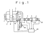
- Figure 1 is a schematic view of a device for purifying the exhaust gas of a diesel engine according to a first example not being part of the present invention.
- reference numeral 1 designates a diesel engine, 2 an intake system, 3 an exhaust system.
- the exhaust system 3 has a filter 4 for collecting particulates contained in exhaust gas, and an oxidation catalyst 5 upstream of the filter 4.
- a diesel fuel supply unit 6 is arranged and an electric heater unit 7 is arranged between the diesel fuel supply unit 6 and the oxidation catalyst 5.
- a throttle valve 8 is arranged upstream of an intake-manifold.
- Reference numeral 9 designates an exhaust gas recirculation (EGR) passage which connects the intake system 2 upstream of the intake-manifold with the exhaust system 3 downstream of an exhaust-manifold and upstream of the diesel fuel supply unit 6.
- EGR exhaust gas recirculation
- the filter 4 Once the filter 4 collects a large amount of particulates, the exhaust resistance in the exhaust system 3 becomes very large and the engine power drops. Accordingly, it is determined if the filter 4 must be regenerated in accordance with a differential exhaust gas pressure between the upstream and the downstream of the filter 4 and the like. When the result is affirmative, the particulates on the filter 4 must be burned. If a temperature of exhaust gas is very high when the result is affirmative, the particulates start to burn naturally. However, if a temperature of exhaust gas is low, the particulates do not start to burn naturally. Accordingly, the diesel fuel supply unit 6 supplies diesel fuel to the oxidation catalyst 5 and diesel fuel is burned thereon and thus the particulates are burned by the heat of the burning diesel fuel.
- the diesel fuel supply unit 6 is connected to a fuel tank (not shown) of the engine 1 via a fuel passage 6c in which a pump 6a is arranged.
- the diesel fuel supply unit 6 has a bypass passage which bypasses the pump 6a and in which a control valve 6b is arranged to regulate an amount of diesel fuel supplied to the filter 4.
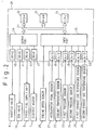
- Reference numeral 30 designates an electronic control unit (ECU) for controlling the throttle valve 8, the EGR valve 10, the diesel fuel supply unit 6, and the electric heater 7.
- the ECU 30 is constructed as a digital computer and includes a ROM (read only memory) 32, a RAM (random access memory) 33, a CPU (microprocessor, etc.) 34, an input port 35, and an output port 36, which are interconnected by a bidirectional bus 31.
- the throttle valve 8, the EGR valve 10, the diesel fuel supply unit 6, and the electric heater 7 are connected to the output port 36 of the ECU 30, via drive circuits 40, 41, 42, and 43, respectively.
- An engine speed sensor 20, which produces output pulses representing the engine speed, is connected to the input port 35.
- An accelerator pedal sensor 21 produces an output voltage which is proportional to the movement of the accelerator pedal, i.e., a current engine load, and this output voltage is input into the input port 35 via an AD converter 45.
- a coolant temperature sensor 22 produces an output voltage which is proportional to the temperature of the cooling water of the engine 1 and is considered to be the engine temperature, and this output voltage is input into the input port 35 via an AD converter 46.
- a first pressure sensor 23 produces an output voltage which is proportional to the exhaust gas pressure immediately upstream of the filter 4, and this output voltage is input into the input port 35 via an AD converter 47.
- a second pressure sensor 24 produces an output voltage which is proportional to the exhaust gas pressure immediately downstream of the filter 4, and this output voltage is input into the input port 35 via an AD converter 48.
- a first exhaust gas temperature sensor 25 produces an output voltage which is proportional to the exhaust gas temperature immediately upstream of the filter 4, and this output voltage is input into the input port 35 via an AD converter 49.
- a second exhaust gas temperature sensor 26 produces an output voltage which is proportional to the exhaust gas temperature immediately downstream of the filter 4, and this output voltage is input into the input port 35 via an AD converter 50.
- the ECU 30 usually controls the opening degree of the throttle valve 8 and of the EGR valve in accordance with a current engine operating condition on the basis of the outputs of the engine speed sensor 20, the accelerator pedal sensor 21, and the coolant temperature sensor 22.
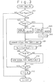
- the ECU 30 controls the diesel fuel supply unit 6 and the electric heater 7, according to a first routine shown in figure 3. The routine is started simultaneously with the engine starting and is repeated at every predetermined period.
- step 101 it is determined if a difference [Pin-Pout] between exhaust gas pressures upstream and downstream of the filter 4 detected by the first and second exhaust gas pressure sensors 23 and 24 is larger than a predetermined pressure [P].
- a difference [Pin-Pout] between exhaust gas pressures upstream and downstream of the filter 4 detected by the first and second exhaust gas pressure sensors 23 and 24 is larger than a predetermined pressure [P].
- a temperature [Tin] of the exhaust gas flowing into the filter 4 is measured by the first exhaust gas temperature sensor 25, and it is determined if the temperature [Tin] is equal to or higher than a first predetermined temperature [T1].
- the routine goes to step 104 and the electric heater 7 is turned on and the routine goes to step 107.
- the routine goes to step 105 and the electric heater 7 is turned off.
- a count value [n] which is reset to [0] initially, is increased by [1] and the routine goes to step 107.
- the diesel fuel supply unit 6 is operated and thus diesel fuel is supplied to the oxidation catalyst 5.
- the temperature [Tout] of the exhaust gas flowing out from the filter 4 is measured by the second exhaust gas temperature sensor 26, and an average [Ta] of the temperatures [Tin] and [Tout] is calculated, as the temperature of the filter 4.
- the routine goes to step 111 and it is determined if the count value [n] is equal to or smaller than a predetermined value [N]. When the result is affirmative, the routine returns to step 103. Thus, the above-mentioned process is repeated until the result at step 111 is negative.
- the routine goes to step 112 and the count value [n] is reset to [0] and the routine is stopped.
- the electric heater 7 when the filter 4 must be regenerated, if a temperature [Tin] of exhaust gas flowing into the filter 4 is lower than the first predetermined temperature [T1], i.e., if a temperature of the oxidation catalyst 5 is low and the oxidation catalyst 5 cannot vaporize the diesel fuel supplied thereto, the electric heater 7 is turned on.
- the electric heater 7 which is arranged between the diesel fuel supply unit 6 and the oxidation catalyst 5 is relative small size and has a small heat capacity so that the temperature thereof rises immediately. Therefore, the diesel fuel supplied from the diesel fuel supply unit 6 to the oxidation catalyst 5 can be vaporized.
- the vaporized diesel fuel can be surely burned thereby.
- a temperature of the oxidation catalyst 5 itself rises due to the heat thereof.
- liquid diesel fuel is supplied to the oxidation catalyst 5, it can surely vaporize the liquid diesel fuel so that the electric heater 7 can be turned off.
- a temperature [Tin] of exhaust gas flowing into the filter 4 rises so that the particulates are burned at the filter 4.
- the filter 4 absorbs the heat from the exhaust gas so that a temperature [Tout] of exhaust gas flowing out from the filter 4 is lower than the temperature [Tin] of exhaust gas flowing into the filter 4.
- exhaust gas in the filter 4 is heated by the burning heat of the particulates, so that the temperature [Tout] of the exhaust gas flowing out from the filter 4 is higher than the temperature [Tin] of exhaust gas flowing into the filter 4.
- the temperature of the filter 4 is between the temperatures [Tin] and [Tout], and is calculated as an average of the temperatures [Tin] and [Tout].
- the temperature of the filter 4 becomes higher than the second predetermined temperature [T2]
- the particulates burn sufficiently. Therefore, even if a temperature [Tin] of exhaust gas flowing into the filter 4 is low, the remainder of the particulates can be burned by the burning heat of the particulates so that the diesel fuel supply unit 6 can be stopped.
- the count value [n] corresponds to an elapsed time after the electric heater 7 is turned off.
- the count value [n] reaches the predetermined value [N]
- all of the particulates have burned out and the regeneration of the filter 4 has been finished so that the routine is stopped.
- the filter 4 must be regenerated, if a temperature [Tin] of exhaust gas flowing into the filter 4 is high and the diesel fuel supplied to the oxidation catalyst 5 can be vaporized thereon, it is not necessary that the electric heater 7 is turned on.
- the first predetermined temperature [T1] at step 103 is a temperature at which such supplied diesel fuel can be vaporized and varies such that higher it becomes, larger is the determined amount of diesel fuel per the unit time.
- Figure 4 shows a second routine for controlling the diesel fuel supply unit 6 and the electric heater 7.
- the differences between the first routine and the second routine only are explained.
- a process at step 202 is added. The process is that a current degree of opening of the throttle valve 8, which is determined in accordance with a current engine operating condition, is decreased for a short time. Therefore, in the initial step of the diesel fuel supplying, a flow rate of intake air becomes small and a flow rate of exhaust gas can be made small so that the supplied amount of diesel fuel per the unit time can be made small and the first predetermined temperature [T1] becomes low. Accordingly, a period for turning on the electric heater 7 can be made small.
- the degree of opening of the throttle valve 8 is returned to the determined one in accordance with the current engine operating condition, and the supplied amount of diesel fuel per the unit time is increased.
- the temperature thereof rises so that the supplied diesel fuel can be vaporized sufficiently:
- the temperature of the oxidation catalyst 5 at which the diesel fuel can be supplied thereto can be set lower so that the engine operating condition area in which the filter 4 can be regenerated is enlarged. It is not preferable to decrease a flow rate of intake air in the engine operation. However, this is for a short time and a large problem does not occur. Moreover, during deceleration, no problem occurs.
- FIG. 5 shows a third routine for controlling the diesel fuel supply unit 6 and the electric heater 7. The differences between the first routine and the third routine only are explained.
- a process at step 302 is added. The process is that a current degree of opening of the throttle valve 8, which is determined in accordance with a current engine operating condition, is decreased, and a current degree of opening of the EGR valve 10, which is determined in accordance with a current engine operating condition, is increased for a short time.
- the flow rate of exhaust gas is not changed but the temperature of exhaust gas can be made high to increase an amount of the recirculation exhaust gas so that the supplied amount of diesel fuel per the unit time can be made small so that a period for turning on the electric heater 7 can be made small.
- the engine operating condition area in which the filter 4 can be regenerated is enlarged.
- FIG. 6 shows a schematic view of a device for purifying the exhaust gas of a diesel engine according to a second example not being part of the present invention.
- the EGR passage 9' connects the intake system 2 upstream of the intake-manifold with the exhaust system 3 between the oxidation catalyst 5 and the filter 4.
- the compressed air contains the diesel fuel so that a combustion speed becomes high, and a good combustion can be realized, and the amounts of CO, HC, and NOx contained in the exhaust gas can be reduced.
- FIG. 7 shows a schematic view of a device for purifying the exhaust gas of a diesel engine according to a third example not being part of the present invention.
- the fuel passage 6c' of the diesel fuel supply unit 6' connects the fuel tank of the engine 1 via a heat exchanger 6d' which is arranged around the exhaust system 3 downstream of the filter 4.
- the fuel passage 6c' downstream of the heat exchanger 6d' is filled with diesel fuel which has a low molecular weight.
- the diesel fuel which has a light molecular weight is supplied to the oxidation catalyst 5.
- the low molecular-weight diesel fuel is vaporized easier than normal diesel fuel. Accordingly, when the temperature of the oxidation catalyst 5 is low, the supplied diesel fuel can be vaporized so that the electric heater 7 can be made smaller than in the first embodiment. On the other hand, in the case that the electric heater 7 is eliminated, a temperature of the oxidation catalyst 5 at which the diesel fuel can be supplied thereto can be set lower so that the engine operating condition area in which the filter 4 can be regenerated enlarges.
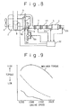
- FIG 8 shows a schematic view of a device for purifying the exhaust gas of a diesel engine according to an embodiment of the present invention.
- an absorption unit 11 which absorbs hydrocarbon, i.e., diesel fuel, is arranged between the electric heater 7 and the oxidation catalyst 5.
- the absorption unit 11 absorbs the diesel fuel vaporized by the electric heater 7, or liquid diesel fuel when the electric heater 7 is turned off. Thereafter the absorption unit 11 initially releases only the light molecular weight components of the absorbed diesel fuel.
- the components have low boiling points so that they are easy to burn in the oxidation catalyst 5.
- a temperature of the oxidation catalyst 5 at which the components of the diesel fuel can be burned is low so that the engine operating condition area in which the filter 4 can be regenerated enlarges.
- the absorption unit 11 releases the heavy molecular weight components of the absorbed diesel fuel.
- the light molecular weight components have already burned in the oxidation catalyst 5 and the temperature thereof has already risen so that the heavy molecular weight components can be burned in the oxidation catalyst 5.
- the electric heater 7 can be replaced by a heating means which can use any energy other than electric energy, for example, a burner. Moreover, in the case that the electric heater 7 is replaced with an electric heating tape catalytic converter, when the electric heating type catalytic converter functions as the catalytic converter, it purifies the particulates in exhaust gas so that the time to regenerate the filter 4 can be extended.
- Figure 9 is a map showing the engine operating condition areas in which the filter can be regenerated.
- the area in the prior art is above the dotted line, and the area in the first embodiment which has the electric heater is above the solid line.
- the area in which the filter can be regenerated can be extended considerably.
Claims (5)
- Dispositif de purification des gaz d'échappement d'un moteur Diesel, comprenant :un filtre destiné à recueillir les particules, qui est disposé dans le système d'échappement du moteur ;un catalyseur d'oxydation disposé dans ledit système d'échappement en amont dudit filtre ;un moyen de délivrance de carburant Diesel destiné à délivrer du carburant Diesel audit catalyseur d'oxydation quand ledit filtre doit être régénéré ;un moyen de diminution de l'air d'admission destiné à diminuer la quantité d'air d'admission dans l'étape initiale de délivrance du carburant Diesel ; etun moyen de diminution du carburant Diesel destiné à diminuer la quantité de carburant Diesel délivré par ledit moyen de délivrance de carburant Diesel quand la quantité d'air d'admission est réduite par ledit moyen de diminution de l'air d'admission.
- Dispositif selon la revendication 1, dans lequel ledit moyen de délivrance de carburant Diesel comporte un passage de carburant relié au réservoir de carburant dudit moteur.
- Dispositif selon la revendication 1, dans lequel ledit moteur Diesel comporte un système de recirculation des gaz d'échappement qui relie le système d'admission du moteur au système d'échappement, entre ledit catalyseur d'oxydation et ledit filtre.
- Dispositif selon la revendication 1, dans lequel ledit moteur Diesel comporte un système de recirculation des gaz d'échappement, ledit dispositif comporte en outre un moyen d'augmentation des gaz d'échappement de recirculation, destiné à augmenter la quantité des gaz d'échappement de recirculation quand la quantité d'air d'admission est réduite par ledit moyen de diminution de l'air d'admission.
- Dispositif selon la revendication 4, dans lequel ledit système de recirculation des gaz d'échappement relie le système d'admission du moteur avec le système d'échappement, entre ledit catalyseur d'oxydation et ledit filtre.
Applications Claiming Priority (3)
| Application Number | Priority Date | Filing Date | Title |
|---|---|---|---|
| JP07119852A JP3089989B2 (ja) | 1995-05-18 | 1995-05-18 | ディーゼル機関の排気浄化装置 |
| JP11985295 | 1995-05-18 | ||
| EP96107919A EP0743429B1 (fr) | 1995-05-18 | 1996-05-17 | Dispositif de purification des gaz d'échappement d'un moteur diesel |
Related Parent Applications (3)
| Application Number | Title | Priority Date | Filing Date |
|---|---|---|---|
| EP96107919A Division EP0743429B1 (fr) | 1995-05-18 | 1996-05-17 | Dispositif de purification des gaz d'échappement d'un moteur diesel |
| EP96107919A Division-Into EP0743429B1 (fr) | 1995-05-18 | 1996-05-17 | Dispositif de purification des gaz d'échappement d'un moteur diesel |
| EP96107919.1 Division | 1996-05-17 |
Publications (3)
| Publication Number | Publication Date |
|---|---|
| EP1158143A2 EP1158143A2 (fr) | 2001-11-28 |
| EP1158143A3 EP1158143A3 (fr) | 2004-12-29 |
| EP1158143B1 true EP1158143B1 (fr) | 2006-03-22 |
Family
ID=14771873
Family Applications (2)
| Application Number | Title | Priority Date | Filing Date |
|---|---|---|---|
| EP96107919A Expired - Lifetime EP0743429B1 (fr) | 1995-05-18 | 1996-05-17 | Dispositif de purification des gaz d'échappement d'un moteur diesel |
| EP01119165A Expired - Lifetime EP1158143B1 (fr) | 1995-05-18 | 1996-05-17 | Dispositif de purification des gaz d'échappement d'un moteur diesel |
Family Applications Before (1)
| Application Number | Title | Priority Date | Filing Date |
|---|---|---|---|
| EP96107919A Expired - Lifetime EP0743429B1 (fr) | 1995-05-18 | 1996-05-17 | Dispositif de purification des gaz d'échappement d'un moteur diesel |
Country Status (4)
| Country | Link |
|---|---|
| US (1) | US5711149A (fr) |
| EP (2) | EP0743429B1 (fr) |
| JP (1) | JP3089989B2 (fr) |
| DE (2) | DE69635935T8 (fr) |
Families Citing this family (124)
| Publication number | Priority date | Publication date | Assignee | Title |
|---|---|---|---|---|
| US6021639A (en) * | 1995-06-28 | 2000-02-08 | Mitsubishi Heavy Industries, Ltd. | Black smoke eliminating device for internal combustion engine and exhaust gas cleaning system including the device |
| JPH0913946A (ja) * | 1995-06-28 | 1997-01-14 | Mitsubishi Heavy Ind Ltd | 黒煙除去装置を備えた排ガス浄化装置 |
| JPH0988691A (ja) * | 1995-09-20 | 1997-03-31 | Toyota Motor Corp | 圧縮着火内燃機関 |
| DE69625823T2 (de) * | 1995-10-30 | 2003-09-04 | Toyota Motor Co Ltd | Abgaskontrollvorrichtung für brennkraftmaschine |
| JP3557815B2 (ja) * | 1996-11-01 | 2004-08-25 | トヨタ自動車株式会社 | 内燃機関の排気浄化装置 |
| JP3427685B2 (ja) * | 1997-07-31 | 2003-07-22 | トヨタ自動車株式会社 | 内燃機関の排気浄化装置 |
| US8833062B1 (en) | 2013-03-15 | 2014-09-16 | Daimier Ag | Catalytic reduction of NOx |
| GB9802504D0 (en) | 1998-02-06 | 1998-04-01 | Johnson Matthey Plc | Improvements in emission control |
| JP3252793B2 (ja) * | 1998-05-15 | 2002-02-04 | トヨタ自動車株式会社 | 内燃機関の排気浄化装置 |
| US6013599A (en) * | 1998-07-15 | 2000-01-11 | Redem Corporation | Self-regenerating diesel exhaust particulate filter and material |
| JP3591317B2 (ja) * | 1998-08-17 | 2004-11-17 | トヨタ自動車株式会社 | 内燃機関の排気還流バルブ強制駆動装置 |
| US6560958B1 (en) * | 1998-10-29 | 2003-05-13 | Massachusetts Institute Of Technology | Emission abatement system |
| DE19957715C2 (de) * | 1998-12-01 | 2002-01-17 | Toyota Motor Co Ltd | Abgasausstoß-Steuerungsvorrichtung für eine Brennkraftmaschine |
| FR2787037B1 (fr) * | 1998-12-09 | 2002-01-11 | Inst Francais Du Petrole | Procede et dispositif d'elimination des oxydes d'azote dans une ligne d'echappement de moteur a combustion interne |
| US6293096B1 (en) | 1999-06-23 | 2001-09-25 | Southwest Research Institute | Multiple stage aftertreatment system |
| US6615580B1 (en) | 1999-06-23 | 2003-09-09 | Southwest Research Institute | Integrated system for controlling diesel engine emissions |
| DE19952830A1 (de) * | 1999-11-02 | 2001-05-03 | Audi Ag | Verfahren zur Abgasnachbehandlung durch Nacheinspritzung von Kraftstoff bei einer Diesel-Brennkraftmaschine mit Vorkatalysator und Partikelfilter |
| FR2804175B1 (fr) * | 2000-01-20 | 2002-04-12 | Peugeot Citroen Automobiles Sa | Systeme d'aide a la regeneration d'un filtre a particules integre dans une ligne d'echappement d'un moteur diesel de vehicule automobile |
| FR2804168B1 (fr) * | 2000-01-20 | 2002-08-02 | Peugeot Citroen Automobiles Sa | Systeme d'aide a la regeneration d'un filtre a particules integre dans une ligne d'echappement d'un moteur diesel de vehicule automobile |
| US6769245B2 (en) | 2000-02-16 | 2004-08-03 | Toyota Jidosha Kabushiki Kaisha | Exhaust gas purification method |
| US6470673B1 (en) | 2000-02-22 | 2002-10-29 | Ford Global Technologies, Inc. | Control of a NOX reductant delivery system |
| US6370868B1 (en) * | 2000-04-04 | 2002-04-16 | Ford Global Technologies, Inc. | Method and system for purge cycle management of a lean NOx trap |
| DE10023439A1 (de) * | 2000-05-12 | 2001-11-22 | Dmc2 Degussa Metals Catalysts | Verfahren zur Entfernung von Stickoxiden und Rußpartikeln aus dem mageren Abgas eines Verbrennungsmotors und Abgasreinigungssystem hierfür |
| US6467257B1 (en) | 2000-06-19 | 2002-10-22 | Southwest Research Institute | System for reducing the nitrogen oxide (NOx) and particulate matter (PM) emissions from internal combustion engines |
| US6397587B1 (en) * | 2000-08-25 | 2002-06-04 | Frod Global Tech., Inc. | System and method for monitoring the loading of a diesel particulate filter |
| JP4889873B2 (ja) | 2000-09-08 | 2012-03-07 | 日産自動車株式会社 | 排気ガス浄化システム、これに用いる排気ガス浄化触媒及び排気浄化方法 |
| US6758036B1 (en) * | 2000-10-27 | 2004-07-06 | Delphi Technologies, Inc. | Method for sulfur protection of NOx adsorber |
| US6598387B2 (en) * | 2000-12-21 | 2003-07-29 | Ford Global Technologies, Llc | Reduction of exhaust smoke emissions following extended diesel engine idling |
| DE10100419A1 (de) * | 2001-01-08 | 2002-07-11 | Bosch Gmbh Robert | Verfahren und Vorrichtung zur Steuerung eines Abgasnachbehandlungssystems |
| US6622480B2 (en) * | 2001-02-21 | 2003-09-23 | Isuzu Motors Limited | Diesel particulate filter unit and regeneration control method of the same |
| DE10118327A1 (de) * | 2001-04-12 | 2002-10-17 | Emitec Emissionstechnologie | Abgassystem |
| FR2829180B1 (fr) * | 2001-08-28 | 2005-10-28 | Ct De Rech S En Machines Therm | Procede de regeneration d'un dispositif de filtration des gaz d'echappement pour un moteur diesel et dispositif de mise en oeuvre |
| KR100504422B1 (ko) * | 2001-09-07 | 2005-07-29 | 미쓰비시 지도샤 고교(주) | 엔진의 배기 정화 장치 |
| EP1296050B1 (fr) | 2001-09-25 | 2006-08-16 | Ford Global Technologies, LLC | Système et procédé de régénération d'un dispositif de traitement de gaz d'échappement |
| JP4042399B2 (ja) * | 2001-12-12 | 2008-02-06 | 三菱自動車工業株式会社 | 排気浄化装置 |
| US20030113242A1 (en) * | 2001-12-18 | 2003-06-19 | Hepburn Jeffrey Scott | Emission control device for an engine |
| US6976353B2 (en) * | 2002-01-25 | 2005-12-20 | Arvin Technologies, Inc. | Apparatus and method for operating a fuel reformer to provide reformate gas to both a fuel cell and an emission abatement device |
| US20040116276A1 (en) * | 2002-02-12 | 2004-06-17 | Aleksey Yezerets | Exhaust aftertreatment emission control regeneration |
| JP3855818B2 (ja) | 2002-03-28 | 2006-12-13 | 日産自動車株式会社 | ディーゼルエンジンの排気浄化装置 |
| WO2003091551A1 (fr) * | 2002-04-24 | 2003-11-06 | Arvin Technologies, Inc. | Dispositif et procede de regeneration d'un filtre a particules d'un systeme d'echappement d'un moteur a combustion interne |
| US7137246B2 (en) * | 2002-04-24 | 2006-11-21 | Ford Global Technologies, Llc | Control for diesel engine with particulate filter |
| SE522146C2 (sv) * | 2002-05-07 | 2004-01-20 | Volvo Lastvagnar Ab | Metod för regenerering av ett partikelfilter vid motorbromsning samt fordon i vilket en sådan metod utnyttjas |
| KR20030096939A (ko) * | 2002-06-18 | 2003-12-31 | 현대자동차주식회사 | 디젤 엔진의 입자상 물질 제거용 필터의 재생 장치 |
| US6694727B1 (en) * | 2002-09-03 | 2004-02-24 | Arvin Technologies, Inc. | Exhaust processor |
| US6971337B2 (en) * | 2002-10-16 | 2005-12-06 | Ethyl Corporation | Emissions control system for diesel fuel combustion after treatment system |
| JP2004162613A (ja) * | 2002-11-13 | 2004-06-10 | Mitsubishi Fuso Truck & Bus Corp | 内燃機関の排気浄化装置 |
| US6832473B2 (en) * | 2002-11-21 | 2004-12-21 | Delphi Technologies, Inc. | Method and system for regenerating NOx adsorbers and/or particulate filters |
| JP2004176663A (ja) * | 2002-11-28 | 2004-06-24 | Honda Motor Co Ltd | 内燃機関の排気浄化装置 |
| DE10256769B4 (de) * | 2002-12-05 | 2005-10-06 | Zeuna-Stärker GmbH & Co KG | Kraftfahrzeug mit einem Diesel-Antriebsmotor |
| JP3894125B2 (ja) * | 2003-01-28 | 2007-03-14 | 日産自動車株式会社 | 内燃機関の排気浄化装置 |
| FR2850704A1 (fr) * | 2003-01-31 | 2004-08-06 | Jean Claude Fayard | Procede de post-injection de gazole pour la regeneration de systemes de filtration des gaz d'echappement de moteur diesel |
| JP4288985B2 (ja) * | 2003-03-31 | 2009-07-01 | 株式会社デンソー | 内燃機関の排気浄化装置 |
| US6871489B2 (en) * | 2003-04-16 | 2005-03-29 | Arvin Technologies, Inc. | Thermal management of exhaust systems |
| JP2004324587A (ja) * | 2003-04-25 | 2004-11-18 | Mitsubishi Fuso Truck & Bus Corp | 内燃機関の排気浄化装置 |
| DE10321105A1 (de) * | 2003-05-09 | 2004-12-02 | Emitec Gesellschaft Für Emissionstechnologie Mbh | Regeneration einer Partikelfalle |
| WO2005005797A2 (fr) * | 2003-06-12 | 2005-01-20 | Donaldson Company, Inc. | Procede d'apport de carburant dans un ecoulement transitoire d'un systeme d'echappement |
| JP4428974B2 (ja) * | 2003-09-11 | 2010-03-10 | トヨタ自動車株式会社 | 内燃機関の排気浄化装置 |
| JP2005090359A (ja) * | 2003-09-17 | 2005-04-07 | Nissan Motor Co Ltd | Dpfの再生制御装置 |
| EP1517028B1 (fr) * | 2003-09-17 | 2011-04-06 | Nissan Motor Co., Ltd. | Dispositif de commande de la régénération d'un filtre à particules d'un moteur Diesel |
| DE10344216A1 (de) * | 2003-09-22 | 2005-05-04 | Eberspaecher J Gmbh & Co | Abgasanlage mit Partikelfilter sowie zugehörige Heizeinrichtung und zugehöriges Regenerationsverfahren |
| GB2408470B (en) * | 2003-11-25 | 2007-06-13 | Arvin Internat | An internal combustion engine exhaust system |
| US6862881B1 (en) * | 2003-12-05 | 2005-03-08 | Caterpillar Inc | Method and apparatus for controlling regeneration of a particulate filter |
| US20050150215A1 (en) * | 2004-01-13 | 2005-07-14 | Taylor William Iii | Method and apparatus for operating an airless fuel-fired burner of an emission abatement assembly |
| JP4211611B2 (ja) * | 2004-01-14 | 2009-01-21 | トヨタ自動車株式会社 | 内燃機関の排気浄化装置 |
| WO2005090759A1 (fr) * | 2004-03-16 | 2005-09-29 | Pyroban Ltd | Procede et dispositif ayant trait au regime de regeneration d'un filtre d'echappement |
| JP4161930B2 (ja) * | 2004-04-06 | 2008-10-08 | いすゞ自動車株式会社 | 排気ガス浄化システムの制御方法及び排気ガス浄化システム |
| US7767163B2 (en) * | 2004-04-20 | 2010-08-03 | Umicore Ag & Co. Kg | Exhaust treatment devices |
| US7104048B2 (en) * | 2004-04-30 | 2006-09-12 | General Motors Corporation | Low emission diesel particulate filter (DPF) regeneration |
| FR2873160B1 (fr) * | 2004-07-19 | 2008-02-22 | Renault Sas | Procede de gestion de la regeneration d'un filtre a particules |
| US7159386B2 (en) * | 2004-09-29 | 2007-01-09 | Caterpillar Inc | Crankcase ventilation system |
| US20060101810A1 (en) * | 2004-11-15 | 2006-05-18 | Angelo Theodore G | System for dispensing fuel into an exhaust system of a diesel engine |
| DE102004057434A1 (de) * | 2004-11-27 | 2006-06-08 | Deutz Ag | Oxidationskatalysator und Partikelfilter |
| FR2879654B1 (fr) * | 2004-12-20 | 2010-04-30 | Inst Francais Du Petrole | Procede de regeneration de filtre a particules avec dispositif a combustion catalytique et installation de filtration utilisant un tel procede |
| US20060218902A1 (en) * | 2005-03-31 | 2006-10-05 | Solar Turbines Incorporated | Burner assembly for particulate trap regeneration |
| US20060254260A1 (en) * | 2005-05-16 | 2006-11-16 | Arvinmeritor Emissions Technologies Gmbh | Method and apparatus for piezoelectric injection of agent into exhaust gas for use with emission abatement device |
| US20060277897A1 (en) * | 2005-06-08 | 2006-12-14 | Ralph Slone | NOx reduction system and method |
| US7332142B2 (en) * | 2005-06-17 | 2008-02-19 | Emcon Tehnologies Germany (Augsburg) Gmbh | Method and apparatus for bubble injection of agent into exhaust gas for use with emission abatement device |
| US7435275B2 (en) * | 2005-08-11 | 2008-10-14 | Delphi Technologies, Inc. | System and method of heating an exhaust treatment device |
| US7377102B2 (en) * | 2005-08-11 | 2008-05-27 | Cleanair Systems | Device and method for heating exhaust gas |
| US8615988B2 (en) * | 2005-08-23 | 2013-12-31 | GM Global Technology Operations LLC | Electrical diesel particulate filter (DPF) regeneration |
| US20070084116A1 (en) * | 2005-10-13 | 2007-04-19 | Bayerische Motoren Werke Aktiengesellschaft | Reformer system having electrical heating devices |
| US7861517B2 (en) * | 2005-11-09 | 2011-01-04 | Delphi Technologies, Inc. | Method and system for controlling catalyst temperature |
| FR2897390A3 (fr) * | 2006-02-13 | 2007-08-17 | Renault Sas | Dispositif de traitement des gaz d'echappement d'un moteur a combustion interne de vehicule automobile, et procede associe. |
| US8046988B2 (en) * | 2006-02-28 | 2011-11-01 | Caterpillar Inc. | System having multiple valves operated by common controller |
| CN101415915B (zh) * | 2006-04-07 | 2012-05-09 | 排放控制技术有限公司 | 用于操作减排系统的方法和设备 |
| US7536853B2 (en) * | 2006-06-19 | 2009-05-26 | International Truck Intellectual Property Company, Llc | Heating system for a vehicle having an exhaust system |
| US7788911B2 (en) * | 2006-07-21 | 2010-09-07 | Cummins Filtration, Inc. | Adsorbed substance accumulation reduction for exhaust treatment equipment |
| JP2008057364A (ja) * | 2006-08-30 | 2008-03-13 | Toyota Motor Corp | 内燃機関の排気浄化システム |
| US20080083215A1 (en) * | 2006-10-10 | 2008-04-10 | Mi Yan | Standalone thermal energy recycling device for engine after-treatment systems |
| US7669409B2 (en) * | 2006-10-31 | 2010-03-02 | Caterpillar Inc. | Selective oxidation catalyst injection based on temperature |
| FR2909123B1 (fr) * | 2006-11-27 | 2012-10-05 | Peugeot Citroen Automobiles Sa | Ligne d'echappement des gaz pour moteur a combustion interne equipee de systemes de depolution. |
| US7958723B2 (en) * | 2007-05-15 | 2011-06-14 | GM Global Technology Operations LLC | Electrically heated particulate filter propagation support methods and systems |
| US8069657B2 (en) * | 2007-06-05 | 2011-12-06 | The United States Of America As Represented By The Administrator Of The U.S. Environmental Protection Agency | Diesel particulate filter regeneration system |
| US8037673B2 (en) * | 2007-06-18 | 2011-10-18 | GM Global Technology Operations LLC | Selective catalyst reduction light-off strategy |
| US7966812B2 (en) * | 2007-08-29 | 2011-06-28 | Ford Global Technologies, Llc | Multi-stage regeneration of particulate filter |
| US8156737B2 (en) * | 2007-09-18 | 2012-04-17 | GM Global Technology Operations LLC | Elevated exhaust temperature, zoned, electrically-heated particulate matter filter |
| JP5024066B2 (ja) * | 2008-01-16 | 2012-09-12 | 株式会社デンソー | 内燃機関の排気浄化装置 |
| US8322132B2 (en) * | 2008-04-30 | 2012-12-04 | Perkins Engines Company Limited | Exhaust treatment system implementing regeneration control |
| DE102008033154A1 (de) * | 2008-07-15 | 2010-01-21 | Friedrich Boysen Gmbh & Co. Kg | Regenerationsvorrichtung |
| DE102008038721A1 (de) * | 2008-08-12 | 2010-02-18 | Man Nutzfahrzeuge Ag | Verfahren und Vorrichtung zur Regeneration eines im Abgastrakt einer Brennkraftmaschine angeordneten Partikelfilters |
| JP4569690B2 (ja) * | 2008-09-04 | 2010-10-27 | トヨタ自動車株式会社 | 内燃機関の排気浄化装置 |
| DE102008044309B4 (de) * | 2008-12-03 | 2016-08-18 | Ford Global Technologies, Llc | Modellbasierte dynamische Anpassung des Solltemperaturwertes einer Abgasnachbehandlungseinrichtung |
| US8584445B2 (en) * | 2009-02-04 | 2013-11-19 | GM Global Technology Operations LLC | Method and system for controlling an electrically heated particulate filter |
| DE102009012094A1 (de) * | 2009-03-06 | 2010-09-09 | Emitec Gesellschaft Für Emissionstechnologie Mbh | Verfahren zum Betrieb einer Vorrichtung zur Reinigung von Abgas mit einem Heizapparat |
| US8365517B2 (en) * | 2009-06-11 | 2013-02-05 | GM Global Technology Operations LLC | Apparatus and method for regenerating an exhaust filter |
| US8950177B2 (en) * | 2009-06-17 | 2015-02-10 | GM Global Technology Operations LLC | Detecting particulate matter load density within a particulate filter |
| US8312712B2 (en) * | 2009-06-29 | 2012-11-20 | GM Global Technology Operations LLC | Electrically heated particulate filter regeneration during engine start/stop operation |
| US8341945B2 (en) * | 2009-07-01 | 2013-01-01 | GM Global Technology Operations LLC | Electrically heated particulate filter |
| US8479496B2 (en) * | 2009-07-02 | 2013-07-09 | GM Global Technology Operations LLC | Selective catalytic reduction system using electrically heated catalyst |
| US8443590B2 (en) * | 2009-07-02 | 2013-05-21 | GM Global Technology Operations LLC | Reduced volume electrically heated particulate filter |
| US20110023469A1 (en) * | 2009-07-29 | 2011-02-03 | International Engine Intellectual Property Company, Llc | Heating exhaust gas for diesel particulate filter regeneration |
| US8475574B2 (en) | 2009-08-05 | 2013-07-02 | GM Global Technology Operations LLC | Electric heater and control system and method for electrically heated particulate filters |
| US8511069B2 (en) * | 2009-08-12 | 2013-08-20 | GM Global Technology Operations LLC | Systems and methods for layered regeneration of a particulate matter filter |
| US20110072805A1 (en) * | 2009-09-25 | 2011-03-31 | International Engine Intellectual Property Company Llc | Electrically heated diesel oxidation catalyst |
| US9103253B2 (en) * | 2009-12-16 | 2015-08-11 | Faurecia Emissions Control Technologies, Usa, Llc | Thermal enhancer and hydrocarbon doser |
| US8701388B2 (en) * | 2010-05-10 | 2014-04-22 | GM Global Technology Operations LLC | Exhaust treatment methods and systems |
| ES2628460T3 (es) | 2010-08-20 | 2017-08-02 | Mitsui Mining And Smelting Co., Ltd. | Catalizador de oxidación adecuado para la combustión de un componente de aceite ligero |
| DE102010064020B4 (de) * | 2010-12-23 | 2013-03-07 | Bosch Emission Systems Gmbh & Co. Kg | Abgasanlage und Aufheizverfahren |
| DE102011001596A1 (de) * | 2011-03-28 | 2012-10-04 | Hjs Emission Technology Gmbh & Co. Kg | Verfahren zum Zuführen von thermischer Energie in ein in den Abgasstrang einer Brennkraftmaschine eingeschaltetes Abgasreinigungsaggregat |
| MY164098A (en) * | 2012-03-02 | 2017-11-30 | Continental Automotive Gmbh | Method for operating a heating catalyst |
| CN103277173B (zh) * | 2013-01-18 | 2015-10-07 | 贵州黄帝车辆净化器有限公司 | 柴油发动机排气后处理装置升温控制系统及控制方法 |
| US8850802B1 (en) | 2013-03-15 | 2014-10-07 | Daimler Ag | Catalytic reduction of NOx |
| DE102017115408A1 (de) | 2017-07-10 | 2019-01-10 | Volkswagen Aktiengesellschaft | Abgasnachbehandlungssystem und Verfahren zur Abgasnachbehandlung eines Verbrennungsmotors |
| US10738676B2 (en) | 2018-10-23 | 2020-08-11 | Faurecia Emissions Control Technologies, Usa, Llc | Thermal regenerator for exhaust system |
Family Cites Families (26)
| Publication number | Priority date | Publication date | Assignee | Title |
|---|---|---|---|---|
| FR1382418A (fr) * | 1963-12-17 | 1964-12-18 | Inst Gornogo Dela Sibirskogo O | Neutralisateur catalytique des gaz d'échappement des moteurs à combustion interne |
| US3699683A (en) * | 1971-04-05 | 1972-10-24 | Chemical Construction Corp | Engine exhaust emission control system |
| DE2410644A1 (de) * | 1974-03-06 | 1975-09-18 | Reinhold Dipl Ing Schmidt | Anordnungen an brennkraftmaschinen und/oder feuerungsanlagen bei methanol-betrieb |
| JPS55104757U (fr) * | 1979-01-17 | 1980-07-22 | ||
| JPS55142920A (en) * | 1979-04-24 | 1980-11-07 | Nissan Motor Co Ltd | Soot treatment device for diesel engine |
| US4535588A (en) * | 1979-06-12 | 1985-08-20 | Nippon Soken, Inc. | Carbon particulates cleaning device for diesel engine |
| US4372111A (en) * | 1980-03-03 | 1983-02-08 | Texaco Inc. | Method for cyclic rejuvenation of an exhaust gas filter and apparatus |
| US4322387A (en) * | 1980-10-27 | 1982-03-30 | Texaco Inc. | Catalytic exhaust gas torch |
| US4359863A (en) * | 1980-12-22 | 1982-11-23 | Texaco Inc. | Exhaust gas torch apparatus |
| US4449362A (en) * | 1981-12-02 | 1984-05-22 | Robertshaw Controls Company | Exhaust system for an internal combustion engine, burn-off unit and methods therefor |
| JPS59155523A (ja) * | 1983-02-23 | 1984-09-04 | Toyota Motor Corp | デイ−ゼル排気微粒子捕集装置におけるフイルタ再生装置 |
| JPS61112718A (ja) * | 1984-11-08 | 1986-05-30 | Mitsubishi Motors Corp | デイ−ゼルパテイキユレ−トオキシダイザの再生装置 |
| JPS61122718A (ja) * | 1984-11-20 | 1986-06-10 | Fujitsu Ltd | サ−ボ制御装置 |
| JPH0611776B2 (ja) * | 1985-02-07 | 1994-02-16 | 三井東圧化学株式会社 | 固形レゾ−ル型フエノ−ル樹脂の製造法 |
| JPS63198717A (ja) * | 1987-02-13 | 1988-08-17 | Toyota Central Res & Dev Lab Inc | 内燃機関の排気粒子除去装置 |
| JPS646311A (en) * | 1987-06-27 | 1989-01-10 | Fujikura Ltd | Superconducting oxide wire |
| JPH02196120A (ja) * | 1989-01-24 | 1990-08-02 | Nissan Motor Co Ltd | 内燃機関の排気微粒子処理装置 |
| ZA904363B (en) * | 1989-06-24 | 1991-03-27 | Degussa | Process for the regeneration of soot filters on diesel engines |
| JP2850547B2 (ja) * | 1990-02-09 | 1999-01-27 | トヨタ自動車株式会社 | 内燃機関の排気浄化装置 |
| JPH0419315A (ja) * | 1990-05-10 | 1992-01-23 | Nissan Motor Co Ltd | 内燃機関の排気処理装置 |
| JPH0441914A (ja) * | 1990-06-01 | 1992-02-12 | Nissan Motor Co Ltd | 内燃機関の排気処理装置 |
| JPH04148014A (ja) * | 1990-10-11 | 1992-05-21 | Babcock Hitachi Kk | ディーゼル機関排気微粒子除去装置 |
| JPH05133286A (ja) * | 1991-11-12 | 1993-05-28 | Nissan Motor Co Ltd | デイーゼル機関の排気還流装置 |
| WO1995008703A1 (fr) * | 1993-09-21 | 1995-03-30 | Orbital Engine Company (Australia) Pty. Limited | Traitement catalytique des gaz d'echappement |
| JP2983429B2 (ja) * | 1994-02-25 | 1999-11-29 | 本田技研工業株式会社 | 内燃機関の排気ガス浄化装置 |
| JP3248806B2 (ja) * | 1994-03-18 | 2002-01-21 | 本田技研工業株式会社 | 内燃エンジンの排気ガス浄化装置 |
-
1995
- 1995-05-18 JP JP07119852A patent/JP3089989B2/ja not_active Expired - Fee Related
-
1996
- 1996-05-15 US US08/647,740 patent/US5711149A/en not_active Expired - Lifetime
- 1996-05-17 DE DE69635935T patent/DE69635935T8/de active Active
- 1996-05-17 DE DE69629870T patent/DE69629870T2/de not_active Expired - Lifetime
- 1996-05-17 EP EP96107919A patent/EP0743429B1/fr not_active Expired - Lifetime
- 1996-05-17 EP EP01119165A patent/EP1158143B1/fr not_active Expired - Lifetime
Also Published As
| Publication number | Publication date |
|---|---|
| DE69635935D1 (de) | 2006-05-11 |
| JPH08312331A (ja) | 1996-11-26 |
| EP0743429B1 (fr) | 2003-09-10 |
| EP1158143A2 (fr) | 2001-11-28 |
| DE69635935T2 (de) | 2007-03-15 |
| DE69635935T8 (de) | 2007-09-06 |
| EP1158143A3 (fr) | 2004-12-29 |
| JP3089989B2 (ja) | 2000-09-18 |
| DE69629870D1 (de) | 2003-10-16 |
| US5711149A (en) | 1998-01-27 |
| EP0743429A2 (fr) | 1996-11-20 |
| DE69629870T2 (de) | 2004-07-15 |
| EP0743429A3 (fr) | 1998-06-10 |
Similar Documents
| Publication | Publication Date | Title |
|---|---|---|
| EP1158143B1 (fr) | Dispositif de purification des gaz d'échappement d'un moteur diesel | |
| EP1174600B1 (fr) | Système et méthode de contrôle des émissions d'un moteur à combustion interne | |
| EP1978219B1 (fr) | Procédé et système de purification de gaz d'échappement | |
| US20090107117A1 (en) | Diesel Engine Aftertreatment Control Operation with Waste Heat Recovery | |
| JP3201237B2 (ja) | 内燃機関の排気浄化装置 | |
| JPS62616A (ja) | 排気微粒子濾過器の再生装置 | |
| CA1216200A (fr) | Fonctionnement d'un capteur de recyclage pour moteur diesel | |
| JPS62162762A (ja) | デイ−ゼル機関の排気ガス浄化装置 | |
| JP2001073743A (ja) | ディーゼル機関の排気浄化装置 | |
| JP3385874B2 (ja) | ディーゼル機関の排気浄化装置 | |
| JP3615911B2 (ja) | ディーゼル機関の排ガス浄化装置 | |
| JPS62159713A (ja) | デイ−ゼル機関の排気ガス浄化装置 | |
| JPH0355773Y2 (fr) | ||
| JPH059452Y2 (fr) | ||
| JPH0710035Y2 (ja) | ディーゼルエンジンの白煙低減装置 | |
| JPH0219535Y2 (fr) | ||
| JPH01182517A (ja) | ディーゼルエンジンの排気浄化装置 | |
| JPH0526003B2 (fr) | ||
| JPH0658056B2 (ja) | デイ−ゼル排気ガスフイルタの再生装置 | |
| JPH06229226A (ja) | パティキュレートフィルタの再生時期判断装置 | |
| JPH0219536Y2 (fr) | ||
| JPS6143936Y2 (fr) | ||
| JP2838609B2 (ja) | 内燃機関の排気浄化装置 | |
| JPH0623536B2 (ja) | デイ−ゼル機関の排気ガス浄化装置 | |
| JPH0325607B2 (fr) |
Legal Events
| Date | Code | Title | Description |
|---|---|---|---|
| PUAI | Public reference made under article 153(3) epc to a published international application that has entered the european phase |
Free format text: ORIGINAL CODE: 0009012 |
|
| 17P | Request for examination filed |
Effective date: 20010808 |
|
| AC | Divisional application: reference to earlier application |
Ref document number: 743429 Country of ref document: EP |
|
| AK | Designated contracting states |
Kind code of ref document: A2 Designated state(s): DE FR GB |
|
| PUAL | Search report despatched |
Free format text: ORIGINAL CODE: 0009013 |
|
| AK | Designated contracting states |
Kind code of ref document: A3 Designated state(s): DE FR GB |
|
| 17Q | First examination report despatched |
Effective date: 20050318 |
|
| GRAP | Despatch of communication of intention to grant a patent |
Free format text: ORIGINAL CODE: EPIDOSNIGR1 |
|
| AKX | Designation fees paid |
Designated state(s): DE FR GB |
|
| GRAS | Grant fee paid |
Free format text: ORIGINAL CODE: EPIDOSNIGR3 |
|
| GRAA | (expected) grant |
Free format text: ORIGINAL CODE: 0009210 |
|
| AC | Divisional application: reference to earlier application |
Ref document number: 0743429 Country of ref document: EP Kind code of ref document: P |
|
| AK | Designated contracting states |
Kind code of ref document: B1 Designated state(s): DE FR GB |
|
| REG | Reference to a national code |
Ref country code: GB Ref legal event code: FG4D |
|
| REF | Corresponds to: |
Ref document number: 69635935 Country of ref document: DE Date of ref document: 20060511 Kind code of ref document: P |
|
| ET | Fr: translation filed | ||
| PLBE | No opposition filed within time limit |
Free format text: ORIGINAL CODE: 0009261 |
|
| STAA | Information on the status of an ep patent application or granted ep patent |
Free format text: STATUS: NO OPPOSITION FILED WITHIN TIME LIMIT |
|
| 26N | No opposition filed |
Effective date: 20061227 |
|
| REG | Reference to a national code |
Ref country code: GB Ref legal event code: 746 Effective date: 20070417 |
|
| PGFP | Annual fee paid to national office [announced via postgrant information from national office to epo] |
Ref country code: DE Payment date: 20130515 Year of fee payment: 18 Ref country code: GB Payment date: 20130515 Year of fee payment: 18 |
|
| PGFP | Annual fee paid to national office [announced via postgrant information from national office to epo] |
Ref country code: FR Payment date: 20130531 Year of fee payment: 18 |
|
| REG | Reference to a national code |
Ref country code: DE Ref legal event code: R119 Ref document number: 69635935 Country of ref document: DE |
|
| GBPC | Gb: european patent ceased through non-payment of renewal fee |
Effective date: 20140517 |
|
| REG | Reference to a national code |
Ref country code: DE Ref legal event code: R119 Ref document number: 69635935 Country of ref document: DE Effective date: 20141202 |
|
| REG | Reference to a national code |
Ref country code: FR Ref legal event code: ST Effective date: 20150130 |
|
| PG25 | Lapsed in a contracting state [announced via postgrant information from national office to epo] |
Ref country code: DE Free format text: LAPSE BECAUSE OF NON-PAYMENT OF DUE FEES Effective date: 20141202 |
|
| PG25 | Lapsed in a contracting state [announced via postgrant information from national office to epo] |
Ref country code: FR Free format text: LAPSE BECAUSE OF NON-PAYMENT OF DUE FEES Effective date: 20140602 Ref country code: GB Free format text: LAPSE BECAUSE OF NON-PAYMENT OF DUE FEES Effective date: 20140517 |