EP1156463B1 - Dentalmodell - Google Patents
Dentalmodell Download PDFInfo
- Publication number
- EP1156463B1 EP1156463B1 EP01106948A EP01106948A EP1156463B1 EP 1156463 B1 EP1156463 B1 EP 1156463B1 EP 01106948 A EP01106948 A EP 01106948A EP 01106948 A EP01106948 A EP 01106948A EP 1156463 B1 EP1156463 B1 EP 1156463B1
- Authority
- EP
- European Patent Office
- Prior art keywords
- teeth
- dental model
- model according
- recesses
- retaining plate
- Prior art date
- Legal status (The legal status is an assumption and is not a legal conclusion. Google has not performed a legal analysis and makes no representation as to the accuracy of the status listed.)
- Expired - Lifetime
Links
- 239000000463 material Substances 0.000 claims description 10
- 229920001206 natural gum Polymers 0.000 claims description 4
- 239000004033 plastic Substances 0.000 claims description 4
- 229920003023 plastic Polymers 0.000 claims description 4
- 239000002131 composite material Substances 0.000 claims description 2
- 239000000203 mixture Substances 0.000 claims 8
- 230000001464 adherent effect Effects 0.000 claims 1
- 238000010276 construction Methods 0.000 claims 1
- 239000000945 filler Substances 0.000 claims 1
- 230000015572 biosynthetic process Effects 0.000 abstract description 2
- 238000005755 formation reaction Methods 0.000 abstract 1
- 210000001909 alveolar process Anatomy 0.000 description 10
- 210000001847 jaw Anatomy 0.000 description 6
- 238000005553 drilling Methods 0.000 description 5
- 230000002349 favourable effect Effects 0.000 description 5
- 239000000428 dust Substances 0.000 description 4
- 238000003860 storage Methods 0.000 description 3
- 238000005520 cutting process Methods 0.000 description 2
- 210000004268 dentin Anatomy 0.000 description 2
- 238000004519 manufacturing process Methods 0.000 description 2
- 229920001296 polysiloxane Polymers 0.000 description 2
- 238000002360 preparation method Methods 0.000 description 2
- 238000004088 simulation Methods 0.000 description 2
- 239000007787 solid Substances 0.000 description 2
- 210000001519 tissue Anatomy 0.000 description 2
- 230000001070 adhesive effect Effects 0.000 description 1
- 230000034303 cell budding Effects 0.000 description 1
- 230000001055 chewing effect Effects 0.000 description 1
- 230000008878 coupling Effects 0.000 description 1
- 238000010168 coupling process Methods 0.000 description 1
- 238000005859 coupling reaction Methods 0.000 description 1
- 238000011161 development Methods 0.000 description 1
- 230000018109 developmental process Effects 0.000 description 1
- 239000013013 elastic material Substances 0.000 description 1
- 239000003822 epoxy resin Substances 0.000 description 1
- 238000000605 extraction Methods 0.000 description 1
- 229920000647 polyepoxide Polymers 0.000 description 1
- 238000007789 sealing Methods 0.000 description 1
- 230000035945 sensitivity Effects 0.000 description 1
- 229920002379 silicone rubber Polymers 0.000 description 1
- 239000004945 silicone rubber Substances 0.000 description 1
- 230000006641 stabilisation Effects 0.000 description 1
- 238000011105 stabilization Methods 0.000 description 1
Images


Classifications
-
- G—PHYSICS
- G09—EDUCATION; CRYPTOGRAPHY; DISPLAY; ADVERTISING; SEALS
- G09B—EDUCATIONAL OR DEMONSTRATION APPLIANCES; APPLIANCES FOR TEACHING, OR COMMUNICATING WITH, THE BLIND, DEAF OR MUTE; MODELS; PLANETARIA; GLOBES; MAPS; DIAGRAMS
- G09B23/00—Models for scientific, medical, or mathematical purposes, e.g. full-sized devices for demonstration purposes
- G09B23/28—Models for scientific, medical, or mathematical purposes, e.g. full-sized devices for demonstration purposes for medicine
- G09B23/283—Models for scientific, medical, or mathematical purposes, e.g. full-sized devices for demonstration purposes for medicine for dentistry or oral hygiene
Definitions
- the invention relates to a dental model, according to the preamble of claim 1, which is intended to be particularly suitable for exercise purposes and for demonstration purposes, preferably for the preparation of carious sites and the supply of the cavity by filling materials.
- the dental model can also be performed all the work that a dentist performs on the patient.
- Such an exercise dental model is known for example from US-PS 38 86 661.
- a ceremoniesszahnsatz is used in a holding plate. Through various elements, the formation of a natural jaw is modeled.
- An advantage of this solution over other known solutions in which the teeth can be replaced only in total, is that depending on the completed exercise result of the machined tooth can be replaced, so that the running costs are so far less.
- special teeth for this replacement-procurement model must be created and maintained so that special storage is required.
- GB-A-2 122 796 describes a dental model in which the fixed support of the replaceable model teeth is to be achieved by undercuts on the stumps of the model teeth in an elastic alveolar crest receiving them. If the tooth is mounted elastically adhering in the associated root recess, drilling dust which gradually slips into the recess gradually deteriorates the adhesive properties, so that the recesses either have to be cleaned up regularly or the model has to be exchanged without further ado.
- the invention has for its object to provide a dental model according to the preamble of claim 1, which is improved in terms of the simple and reliable interchangeability of individual teeth, the bearing safety and the stability of the teeth.
- the dental model should be reusable and largely correspond in form and material to a patient case.
- a particularly advantageous aspect of the present invention can be with the holder according to the invention for a tooth hold on the holding plate and support.
- a sealing of the bearing of the tooth in the recess in the holding plate is automatically ensured at the same time, so that no drilling dust can get into this critical area.
- the pin tooth can thus permanently and stably against lateral forces, such as those introduced by a dental drill, hold in the holding plate made of rigid material.
- the gum mass partially surrounds the tooth so that there is a simulation of a patient's jaw.
- the support of the tooth by the tooth stump on the one hand and friction elements on the other hand causes the tooth occupies exactly the same position when exchanged for another.
- the gum mass can be colored according to the natural gums.
- the holding force of the gum mass can be adapted to the requirements in a wide range.
- an undercut may be provided which acts against an undercut of the tooth and forms a releasable detent.
- the gum mass may also have corresponding undercuts which act against undercuts of the retaining plate.
- both the holding plate and the teeth per respective projecting pin and the gum mass corresponding recesses.
- even if the artificial alveolar ridge forming the recesses for the teeth has rough surfaces on its side surfaces. This ensures that there is also a certain positive connection between the holding plate and gum mass, which promotes the adhesion of the gum mass on the plate.
- gum tissue may be made of pink tinted silicone which is somewhat translucent so that the trajectory of the tooth for the prospective dentist using the dental model for exercise is evident at least in the anterior region of the tooth.
- the teeth of the invention are constructed in a manner known per se multilayer and provided with a tooth stump made of inexpensive plastic.
- the teeth are made of a material.
- the tooth stump fits into the respective associated recess in the alveolar ridge of the retaining plate, whereby the tooth is already firmly mounted due to the conical configuration of both the recess and the tooth stump.
- the tooth Preferably immediately after the area of the tooth stump enclosed by the recess, the tooth has a pin or projection which extends laterally away and forms an undercut.
- the pin or projection engages in a well-fitting recess formed in the dental model, so that the tooth is also held by this friction element.
- the gum tissue has at several points against the retaining plate acting undercuts, so that it adheres firmly to the teeth and the model.
- the model according to the invention can be used as an upper jaw and a lower jaw model. Nevertheless, a slight solubility of the tooth in the guide from the friction and in the recess is ensured, so that the tooth can be easily replaced after an exercise.
- the base plate can be produced from a low-cost plastic as a mass-produced article.
- the holding plate can be in one Insert articulator, so that a chewing simulation is possible and, for example, in the preparation of bridges, the occlusion can be checked. For this purpose, one or two teeth are removed from the dental model without further ado, so that a working model for the bridge production is created.
- the same or corresponding teeth equal shapes of the recess and the associated tooth stump are provided. It is thus possible to reduce the number of different tooth shapes to be kept ready for a dental model, while nevertheless providing unmistakable insertability.
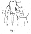
- the dental model 10 shown in plan view in FIG. 3 is shown in a substantial detail in FIG. 1 in section.
- the dental model has a holding plate 12, which is formed in one piece and carries a jaw ridge 14, which has a plurality of recesses which are suitable for receiving teeth 16. are formed of teeth 16 suitable.
- a tooth is shown schematically.
- a recess 17 has oblique, upwardly diverging Treasureinflanken.
- the tooth 16 has a tooth stump 18, which is conical.
- the tooth stub 18 and the recess 17 are non-circular, but preferably oval, and the fit is chosen so that between the tooth stump 18 and the bottom of the recess 17 a certain amount of free space remains.
- a pin 20 extends laterally away, which serves for the exact support of the tooth 16, as explained below.
- the pin 20 rests on the ridge 14, wherein the clamping action between the tooth stump 18 and recess 17 is not affected.
- the cone angle of the tooth stump 18 is preferably between 2 ° and 20 °, preferably between 5 ° and 12 °, and in particular about 8 °. With this configuration, a releasable clamping can be ensured.
- an elastic mass is provided as the gum mass 22, which ensures a connection between the holding plate 12 and the teeth 16.
- the gum mass 22 is made of gummy-colored silicone and encloses the teeth in a way, as well as the natural gums enclosing the teeth.
- the alveolar ridge 14 has a recess 24 into which the pin 20 fits very precisely.
- the pin 20 forms insofar an undercut against a side surface of the recess 24, the elastic resistance for the extraction of the tooth 16 must be overcome.
- the recess 24 is held in the upper region of the alveolar ridge 14 by the cam-shaped pin 20. There, the alveolar crest is still relatively elastic, so that a pulling out of the tooth is possible.
- the bearing between recess 24 and pin 20 supports the Fritationslagerung of the tooth stump 18 in the recess 17th
- the gum mass 22 is applied to the teeth 16 with a slight bias. Falling drill dust can not then penetrate into the bearing gap.
- the gum mass facing the alveolar ridge 14 has structured surfaces 28 and 30. These surfaces are a negative image of the respective associated surfaces of the alveolar ridge 14, so that in this respect a stabilization and improvement of the storage between the holding plate 12 and gum mass 22 is given.
- a bore or für Stammsaus Principleung 31 is provided so that it passes through the retaining plate 12. It extends between the underside of the retaining plate 12 and the recess 17 approximately in the middle.
- the tooth 16 can be fitted with a suitable object, e.g. a thick needle, express.
- a suitable object e.g. a thick needle
- the gum mass 22 terminates slightly below the top 32 of the support plate.
- the holding plate 12 matching edge connection recesses, and the gum mass 22 is extended in a corresponding manner, as can be seen from Fig. 1. This design contributes to improved support while reducing pollution sensitivity.
- Fig. 2 shows that the gum mass is connected to the support plate 12 also with additional undercuts.
- a pin 34 is provided at the rear end of the alveolar ridge 14, which penetrates into an associated recess 36 of the gum mass 22.
- Corresponding connections are also distributed over the alveolar ridge several times, so that the gum mass 22 is fixed on the holding plate 12 as a whole, but because of its elasticity it is also detachably mounted.
- the gum mass 22 extends substantially U-shaped and following the alveolar ridge over the retaining plate 12.
- the teeth 16 are arranged in a true-to-life manner in a row of teeth.
- the material of the retaining profile 12 is a fairly stiff but inexpensive plastic material, e.g. an epoxy resin. Due to the slim design of the ridge 14, however, a certain elasticity is present, so that the budding dentist finds the same mechanical conditions as he encounters later in the mouth of the patient.
- the teeth 16 are made of two or more layers. Preferably, they have a cutting and dentin layer, wherein additionally the tooth stump 18 is added as a further layer.
- the cutting and dentin layer or neck is substantially aligned with the hardness of a natural tooth, so that the practicing student will find the same conditions on the dental model as if he were working on a patient's natural teeth.
- the teeth 16 are made of a composite material and they are industrially prefabricated. Such materials have been described for example in DE 24 03 211 C2 or DE 40 29 230 C2, the disclosure of which is part of this application.
Landscapes
- Engineering & Computer Science (AREA)
- General Physics & Mathematics (AREA)
- Health & Medical Sciences (AREA)
- Physics & Mathematics (AREA)
- Algebra (AREA)
- Mathematical Analysis (AREA)
- General Health & Medical Sciences (AREA)
- Medical Informatics (AREA)
- Medicinal Chemistry (AREA)
- Public Health (AREA)
- Oral & Maxillofacial Surgery (AREA)
- Computational Mathematics (AREA)
- Epidemiology (AREA)
- Chemical & Material Sciences (AREA)
- Mathematical Optimization (AREA)
- Mathematical Physics (AREA)
- Pure & Applied Mathematics (AREA)
- Business, Economics & Management (AREA)
- Educational Administration (AREA)
- Educational Technology (AREA)
- Theoretical Computer Science (AREA)
- Instructional Devices (AREA)
- Dental Tools And Instruments Or Auxiliary Dental Instruments (AREA)
Description
- Die Erfindung betrifft ein Dentalmodell, gemäß dem Oberbegriff von Anspruch 1, das insbesondere für Übungszwecke und für Demonstrationszwecke, vorzugsweise für das Präparieren von kariösen Stellen und die Versorgung der Kavität durch Füllungsmaterialien geeignet sein soll. Am Dentalmodell können ferner alle Arbeiten ausgeführt werden, die ein Zahnarzt am Patienten vornimmt.
- Ein derartiges Übungs-Dentalmodell ist beispielsweise aus der US-PS 38 86 661 bekannt. Bei dieser Lösung ist ein Übungszahnsatz in eine Halteplatte einsetzbar. Über verschiedene Elemente ist auch die Ausbildung eines natürlichen Kiefers nachgebildet. Ein Vorteil dieser Lösung gegenüber weiteren bekannten Lösungen, bei denen die Zähne nur insgesamt ausgetauscht werden können, besteht darin, dass je nach abgeschlossenem Übungsergebnis der bearbeitete Zahn ausgetauscht werden kann, so dass die laufenden Kosten insofern geringer sind. Andererseits müssen jedoch spezielle Zähne für dieses Modell für die Ersatzbeschaffung erzeugt und bereitgehalten werden, so dass eine spezielle Lagerhaltung erforderlich ist.
- Auch aus der US-A-2 750 670 ist ein Übungsmodell mit einzeln herausnehmbaren künstlichen Zähnen bekannt, die von einer dem natürlichen Kiefer nachgebildeten Halteplatte aufgenommen werden. Die künstlichen Zähne sind in ihrer Zahn- als auch in ihrer Wurzelform dem natürlichen Vorbild nachempfunden. Insofern besteht auch bei dieser Lösung das bereits weiter oben angesprochene Problem der Ersatzbeschaffung und speziellen Lagerhaltung.
- Ferner ist es bereits vorgeschlagen worden, ein Dentalmodell zu realisieren, das ein hartes Führungsmaterial mit einem elastischen Material als Lagermaterial kombiniert. Hiermit soll die Lagersteifheit des natürlichen Kieferknochens simuliert werden, wobei durch die Verwendung von Silikonkautschuk erreicht werden soll, dass einzelne Zähne entnommen werden können, jedoch nicht versehentlich herausfallen. Bei derartigen Lösungen ist jedoch die Führung und Halterung des Zahns selbst elastisch. Der Zahn weicht damit seitlich aus, wenn Druck ausgeübt wird, so dass ein derartiger Zahn beispielsweise für Modellierarbeiten geeignet ist. Jedoch muss beispielsweise beim Bohren teils auch recht starker seitlicher Druck ausgeübt werden, so dass derartige elastisch gelagerte Kiefermodelle ungeeignet sind.
- Ein weiteres Problem derartiger Dentalmodelle ist die lösbare Lagerung der Zähne. Z.B. wird in der GB-A-2 122 796 ein Zahnmodell beschrieben, bei dem die feste Halterung der auswechselbaren Modellzähne durch Hinterschneidungen an den Stümpfen der Modellzähne in einem diese aufnehmenden elastischen Kieferkamm erreicht werden soll. Wenn der Zahn elastisch haftend in der zugehörigen Wurzelausnehmung gelagert ist, verschlechtert in die Ausnehmung hineinrutschender Bohrstaub nach und nach die Hafteigenschaften, so dass die Ausnehmungen entweder regelmässig aufwendig gesäubert werden müssen oder kurzerhand das Modell ausgetauscht werden muss.
- Bei Dentalmodellen, die die Zähne fest lagern, muss eine besondere Kupplung realisiert werden, um eine einerseits feste, andererseits aber lösbare Unterstützung des Zahns zu gewährleisten. Auch bei den bereits vorgeschlagenen kombinierten Lagerungen aus teils festen und teils elastischen Ausnehmungsbereichen kann der Bohrstaub in den im Bereich der Festlagerung sich ergebenden Spalt rutschen.
- Demgegenüber liegt der Erfindung die Aufgabe zugrunde, ein Dentalmodell gemäß dem Oberbegriff von Anspruch 1 zu schaffen, das hinsichtlich der einfachen und zuverlässigen Austauschbarkeit von einzelnen Zähnen, der Lagersicherheit und der Standfestigkeit der Zähne, verbessert ist. Das Dentalmodell soll mehrfach verwendbar sein und weitgehend in Form und Material einem Patientenfall entsprechen.
- Dieser Aufgabe wird erfindungsgemäß durch Anspruch 1 gelöst. Vorteilhafte Weiterbildungen ergeben sich aus den Unteransprüchen.
- Gemäß einem besonders vorteilhaften Gesichtspunkt der vorliegenden Erfindung lässt sich mit der erfindungsgemäßen Halterung zum einem der Zahn an der Halteplatte festhalten und abstützen. Zum anderen wird zugleich automatisch eine Abdichtung der Lagerung des Zahns in der betreffenden Ausnehmung in der Halteplatte gewährleistet, so daß kein Bohrstaub in diesen kritischen Bereich gelangen kann. Der Stiftzahn läßt sich damit dauerhaft und stabil auch gegen seitliche Kräfte, wie sie beispielsweise durch einen Dentalbohrer eingeleitet werden, in der aus steifem Material bestehenden Halteplatte festhalten. Zusätzlich umgibt die Zahnfleischmasse den Zahn teilweise, so daß eine Simulation eines Kiefers eines Patienten vorliegt. Die Abstützung des Zahnes durch den Zahnstumpf einerseits und Friktionselemente andererseits bewirkt, daß der Zahn beim Austausch gegen einen anderen exakt die gleiche Position einnimmt.
- Besonders günstig ist es auch, daß sich ein naturnahes Erscheinungsbild des Dentalmodells ergibt, wobei die Zahnfleischmasse dem natürlichen Zahnfleisch entsprechend eingefärbt sein kann. Die Haltekraft der Zahnfleischmasse läßt sich in weiten Bereichen an die Erfordernisse anpassen. So kann eine Hinterschneidung vorgesehen sein, die gegen eine Hinterschneidung des Zahns wirkt und eine lösbare Raste bildet. Die Zahnfleischmasse kann auch entsprechende Hinterschneidungen aufweisen, die gegen Hinterschneidungen der Halteplatte wirken. Bevorzugt weisen hierbei sowohl die Halteplatte als auch die Zähne je vorstehende Zapfen und die Zahnfleischmasse entsprechende Ausnehmungen auf. Besonders günstig in dem Zusammenhang ist es, wenn auch der die Ausnehmungen für die Zähne bildende künstliche Kieferkamm an seinen Seitenflächen rauhe Oberflächen aufweist. Hierdurch ist gewährleistet, daß auch dort ein gewisser Formschluß zwischen Halteplatte und Zahnfleischmasse entsteht, der die Haftung der Zahnfleischmasse auf der Halteplatte fördert.
- Es versteht sich, daß die Vorspannung der Zahnfleischmasse beim Arretieren auf den Kieferkamm bzw. gegenüber den Zähnen in weiten Bereichen an die Erfordernisse anpaßbar ist. Die Zahnfleischmasse kann beispielsweise aus rosa eingefärbtem Silikon bestehen, das in begrenztem Maße durchscheinend ist, so daß der Verlauf des Zahns für den angehenden Zahnarzt, der das Dentalmodell zu Übungszwecken verwendet, zumindest im Frontzahnbereich ersichtlich ist.
- Erfindungsgemäß besonders günstig ist es, daß in Großserie hergestellte Zähne für das erfindungsgemäße Dentalmodell verwendet werden können. Hierzu sind die erfindungsgemäßen Zähne in an sich bekannter Weise mehrschichtig aufgebaut und mit einem aus preisgünstigen Kunststoff hergestellten Zahnstumpf versehen. Vorzugsweise sind die Zähne jedoch aus einem Material hergestellt. Der Zahnstumpf paßt in die je zugehörige Ausnehmung im Kieferkamm der Halteplatte, wodurch der Zahn aufgrund der konischen Ausgestaltung sowohl der Ausnehmung als auch des Zahnstumpfs bereits fest gelagert ist.
- Bevorzugt unmittelbar anschließend an den von der Ausnehmung umschlossenen Bereich des Zahnstumpfs weist der Zahn einen Zapfen oder Vorsprung auf, der sich seitlich wegerstreckt und eine Hinterschneidung bildet. Der Zapfen oder Vorsprung greift in eine recht genau passend ausgebildete Ausnehmung in dem Dentalmodell ein, so daß der Zahn auch durch dieses Friktionselement festgehalten wird. Die Zahnfleischmasse weist an mehreren Stellen gegen die Halteplatte wirkende Hinterschneidungen auf, so daß sie fest an den Zähnen und am Modell haftet.
- Das erfindungsgemäße Modell kann als Oberkiefer- und Unterkiefermodell verwendet werden. Dennoch ist eine leichte Lösbarkeit des Zahns in der Führung aus der Friktion und in der Ausnehmung gewährleistet, so daß der Zahn nach einer Übung ohne weiteres ausgetauscht werden kann. Erfindungsgemäß besonders günstig ist es auch, daß die Basisplatte aus einem preisgünstigen Kunststoff als Massenartikel erzeugt werden kann. Dennoch läßt sich die Halteplatte auch in einen Artikulator einsetzen, so daß eine Kausimulation möglich ist und beispielsweise bei der Anfertigung von Brücken die Okklusion überprüft werden kann. Hierzu werden kurzerhand ein oder zwei Zähne aus dem Dentalmodell entfernt, so daß ein Arbeitsmodell für die Brückenfertigung entsteht.
- Gemäß einem vorteilhaften Gesichtspunkt der Erfindung sind für gleiche oder einander entsprechende Zähne gleiche Formen der Ausnehmung und des zugehörigen Zahnstumpfes vorgesehen. So ist es möglich, die für ein Dentalmodell bereitzuhaltenden unterschiedlichen Zahnformen zu reduzieren, wobei dennoch eine unverwechselbare Einsteckbarkeit gegeben ist.
- Weitere Einzelheiten, Vorteile und Merkmale ergeben sich aus der nachfolgenden Beschreibung eines Ausführungebeispiels anhand der Zeichnung.
- Es zeigen:
- Fig. 1
- einen schematisch angedeuteten Schnitt entlang der Linie I-I aus Fig. 3, zur Darstellung eines Details einer erfindungsgemäßen Dentalplatte;
- Fig. 2
- einen schematisch angedeuteten Schnitt entlang der Linie II-II aus Fig. 3, zur Darstellung eines Details einer erfindungsgemäßen Dentalplatte; und
- Fig. 3
- eine Draufsicht auf eine Dentalplatte in einer Ausführungsform der Erfindung in Draufsicht.
- Das in Fig. 3 in der Draufsicht dargestellte Dentalmodell 10 ist in einer wesentlichen Einzelheit in Fig. 1 im Schnitt dargestellt. Das Dentalmodell weist eine Halteplatte 12 auf, die einstückig ausgebildet ist und einen Kieferkamm 14 trägt, der Vielzahl von Ausnehmungen aufweist, die für die Aufnahme von Zähnen 16 geeignet ausgebildet sind. von Zähnen 16 geeignet ausgebildet sind.
- In Fig. 1 ist ein Zahn schematisch dargestellt. Eine Ausnehmung 17 weist schräge, nach oben divergierende Seiteinflanken auf. Hierzu passend weist der Zahn 16 einen Zahnstumpf 18 auf, der konisch ausgebildet ist. Der Zahnstumpf 18 und die Ausnehmung 17 sind nicht-kreisförmig, sondern bevorzugt oval, und die Passung ist so gewählt, daß zwischen dem Zahnstumpf 18 und dem Boden der Ausnehmung 17 ein gewisser Freiraum verbleibt.
- Aufgrund des geringen Konuswinkels hält der Zahn 16 bereits von sich aus recht gut in der Ausnehmung 17.
- Unmittelbar anschließend an den Zahnstumpf 18 erstreckt sich ein Zapfen 20 seitlich weg, der für die exakte Abstützung des Zahns 16 dient, wie es nachstehend erläutert ist. Der Zapfen 20 liegt auf den Kieferkamm 14 auf, wobei die Klemmwirkung zwischen Zahnstumpf 18 und Ausnehmung 17 nicht beeinträchtigt wird. Der Konuswinkel des Zahnstumpfs 18 beträgt bevorzugt zwischen 2° und 20°, vorzugsweise zwischen 5° und 12°, und insbesondere etwa 8°. Mit dieser Ausgestaltung läßt sich eine lösbare Klemmung gewährleisten.
- Den Kieferkamm umgebend und diesen wie auch einen Teil der Zähne 16 intensiv umhüllend ist eine elastische Masse als Zahnfleischmasse 22 vorgesehen, die eine Verbindung zwischen der Halteplatte 12 und den Zähnen 16 sicherstellt. Die Zahnfleischmasse 22 ist aus zahnfleischfarben eingefärbtem Silikon und umschließt die Zähne in einer Weise, wie auch das natürliche Zahnfleisch die Zähne umschließt. Der Kieferkamm 14 weist eine Ausnehmung 24 auf, in die recht genau der Zapfen 20 paßt. Der Zapfen 20 bildet insofern eine Hinterschneidung gegen eine Seitenfläche der Ausnehmung 24, deren elastischer Widerstand für das Ausziehen des Zahns 16 überwunden werden muß.
- Erfindungsgemäß besonders günstig ist es, daß die Ausnehmung 24 im oberen Bereich des Kieferkamms 14 durch den nockenförmigen Zapfen 20 gehalten ist. Dort ist der Kieferkamm noch vergleichsweise elastisch, so daß ein Herausziehen des Zahns möglich ist. Die Lagerung zwischen Ausnehmung 24 und Zapfen 20 unterstützt die Friktionslagerung des Zahnstumpfs 18 in der Ausnehmung 17.
- Bevorzugt liegt die Zahnfleischmasse 22 mit leichter Vorspannung an den Zähnen 16 an. Herabfallendes Bohrmehl kann dann nicht in den Lagerspalt eindringen.
- Ferner weist die Zahnfleischmasse dem Kieferkamm 14 zugewandt strukturierte Oberflächen 28 und 30 auf. Diese Oberflächen sind ein Negativabbild der je zugehörigen Oberflächen des Kieferkamms 14, so daß auch insofern eine Stabilisierung und Verbesserung der Lagerung zwischen Halteplatte 12 und Zahnfleischmasse 22 gegeben ist.
- In dem in Fig. 1 dargestellten Ausführungsbeispiel ist eine Bohrung oder Durchtrittsausnehmung 31 so vorgesehen, daß sie die Halteplatte 12 durchtritt. Sie erstreckt sich zwischen der Unterseite der Halteplatte 12 und der Ausnehmung 17 etwa in deren Mitte. Über diese Bohrung 31 läßt sich der Zahn 16 bei Bedarf mit einem geeigneten Gegenstand, z.B. einer dicken Nadel, ausdrücken. Mit dieser Lösung läßt sich trotz der sehr festen und bohrstabilen Lagerung des Zahns auf der Halteplatte 12 der Zahn bei Bedarf auswechseln.
- Ferner ist vorgesehen, daß die Zahnfleischmasse 22 etwas unterhalb der Oberseite 32 der Halteplatte endet. Hierzu weist die Halteplatte 12 passende Randanschlußvertiefungen auf, und die Zahnfleischmasse 22 ist in entsprechender Weise verlängert, wie es aus Fig. 1 ersichtlich ist. Diese Ausgestaltung trägt zur verbesserten Abstützung bei gleichzeitigero Verminderung der Verschmutzungsempfindlichkeit bei.
- Fig. 2 zeigt, daß die Zahnfleischmasse an der Halteplatte 12 auch mit zusätzlichen Hinterschneidungen verbunden ist. In dieser Beziehung ist am rückwärtigen Ende des Kieferkamms 14 ein Zapfen 34 vorgesehen, der in eine zugehörige Ausnehmung 36 der Zahnfleischmasse 22 eindringt. Entsprechende Verbindungen sind auch über den Kieferkamm verteilt mehrfach vorgesehen, so daß die Zahnfleischmasse 22 insgesamt gut auf der Halteplatte 12 befestigt, aber aufgrund ihrer Elastizität auch lösbar gelagert ist.
- Aus Fig. 3 ist ersichtlich, daß sich die Zahnfleischmasse 22 im wesentlichen U-förmig und dem Kieferkamm folgend über die Halteplatte 12 erstreckt. Die Zähne 16 sind in wirklichkeitsgetreuer Weise in einer Zahnreihe angeordnet. Das Material des Halteprofils 12 ist ein recht steifes, aber preisgünstiges Kunststoffmaterial, z.B. ein Epoxidharz. Aufgrund der schlanken Ausbildung des Kieferkamms 14 ist jedoch eine gewisse Elastizität vorhanden, so daß der angehende Zahnarzt die gleichen mechanischen Verhältnisse vorfindet, wie er sie später im Mund des Patienten antrifft.
- Die Zähne 16 sind aus zwei oder mehreren Schichten hergestellt. Vorzugsweise haben sie eine Schneide- und Dentinschicht, wobei zusätzlich noch der Zahnstumpf 18 als weitere Schicht hinzukommt. Die Schneide- und Dentinschicht bzw. der Zahnhals ist der Härte eines natürlichen Zahnes weitgehend angeglichen, so daß der übende Student am Dentalmodell die gleichen Gegebenheiten vorfindet, wie wenn er an natürlichen Zähnen eines Patienten arbeiten würde.
- Die Zähne 16 sind aus einem Compositmaterial hergestellt und sie werden industriell vorgefertigt. Solche Materialien wurden beispielsweise in der DE 24 03 211 C2 oder in der DE 40 29 230 C2 beschrieben, deren Offenbarung Bestandteil dieser Anmeldung ist.
Claims (17)
- Dentalmodell, insbesondere für Übungszwecke, mit einer Halteplatte mit Ausnehmungen für künstliche Zähne, die je einen Zahnstumpf aufweisen, der in die betreffende Ausnehmung passt, wobei
eine Zahnfleischmasse (22) sowohl die Zähne (16) der Zahnreihe als auch die Ausnehmungen übergreift und die Zähne (16) an der Halteplatte (12) und je in ihren Ausnehmungen (17) mit Friktion lösbar gehalten sind, dadurch gekennzeichnet, dass
die Zähne (16) auf einem die Ausnehmungen aufnehmenden Kieferkamm (14) elastisch klemmend gehalten sind, wobei der Kieferkamm (14) und die Halteplatte (12) eine einstückige Einheit bilden; und
die Zahnfleischmasse (22) und der aufnehmende Kieferkamm (14) trennbare, voneinander unterschiedliche Schichten sind. - Dentalmodell nach Anspruch 1, dadurch gekennzeichnet, dass die Zähne eine Hinterschneidung aufweisen, die gegen je eine Hinterschneidung der Halteplatte (12) wirkt.
- Dentalmodell nach einem der vorhergehenden Ansprüche, dadurch gekennzeichnet, dass die Zähne (16) in der Halteplatte (12) elastisch haftend gehalten sind.
- Dentalmodell nach einem der vorhergehenden Ansprüche, dadurch gekennzeichnet, dass die Zähne (16) in den Ausnehmungen (17) im wesentlichen spielfrei gelagert sind.
- Dentalmodell nach einem der vorhergehenden Ansprüche, dadurch gekennzeichnet, dass die Ausnehmungen (17) von der Halteplatte (12) aus betrachtet divergierende Seitenflanken aufweisen und die Zähne (16) Zahnstümpfe (18) aufweisen, die zu den Seitenflanken passen.
- Dentalmodell nach einem der vorhergehenden Ansprüche, dadurch gekennzeichnet, dass mehrere Hinterschneidungen der Halteplatte (12) für die Lagerung der Zahnfleischmasse (32) verteilt angeordnet sind und zu Hinterschneidungen der Zahnfleischmasse (22) passen und insbesondere die zusammenzufügenden Oberflächen durch Abdruck voneinander hergestellt sind.
- Dentalmodell nach Anspruch 6, dadurch gekennzeichnet, dass die einander zugewandten Oberflächen (28, 30) von Zahnfleischmasse (22) und Halteplatte (12), insbesondere im Bereich des Kieferkamms (14), dem natürlichen Zahnfleisch nachempfundene leichte Erhebungen und Vertiefungen aufweisen, die die Haftung verbessern.
- Dentalmodell nach einem der vorhergehenden Ansprüche, dadurch gekennzeichnet, dass die Zahnfleischmasse (22) dem natürlichen Zahnfleisch nachempfundene Erhebungen und Vertiefungen an ihren Außenflächen aufweist.
- Dentalmodell nach einem der vorhergehenden Ansprüche, dadurch gekennzeichnet, dass die Zähne (16) großtechnisch hergestellten Zähnen entsprechen, was den Schichtaufbau angeht.
- Dentalmodell nach Anspruch 9, dadurch gekennzeichnet, dass die großtechnisch hergestellten Zähne (16) an ihren Zahnstümpfen (18) abgeschnitten sind und sich bis etwas oberhalb des Grundes der je ausgebildeten Ausnehmung (17) in der Halteplatte (12) erstrecken.
- Dentalmodell nach einem der vorhergehenden Ansprüche, dadurch gekennzeichnet, dass die Zähne (16) aus Composite, also einem mit Füllstoff gefüllten Kunststoffmaterial, bestehen, dessen Härte der Härte des natürlichen Zahns entspricht.
- Dentalmodell nach einem der vorhergehenden Ansprüche, dadurch gekennzeichnet, dass Zahnstumpf (18) und Ausnehmungen (17) in ihrer Ausgestaltung und Lagersteifheit an die Lagersteifheit des natürlichen Kieferknochens für einen natürlichen Zahn angepasst sind.
- Dentalmodell nach einem der vorhergehenden Ansprüche, dadurch gekennzeichnet, dass die Halteplatte (12) eine Randanschlussvertiefung für die Zahnfleischmasse (22) aufweist, die einen im wesentlichen bündigen Anschluss der Zahnfleischmasse (22) an die Halteplatte (12) erlaubt.
- Dentalmodell nach einem der vorhergehenden Ansprüche, dadurch gekennzeichnet, dass die Zähne (16) nach Gebrauch einzeln aus der Führung in der Halteplatte (12) auslösbar sind.
- Dentalmodell nach einem der vorhergehenden Ansprüche, dadurch gekennzeichnet, dass die Halteplatte (12) Durchtrittsausnehmungen aufweist, die sich nach der Art von Bohrungen (31) unten an die Ausnehmungen (17) für die Zähne (16) anschließen.
- Dentalmodell nach einem der vorhergehenden Ansprüche, dadurch gekennzeichnet, dass die Zahnstümpfe (18) von mindestens zwei zueinander benachbarten Zähnen (16) übereinstimmen, jedoch gegenüber mindestens einem weiteren Zahnstumpf (18) unterschiedlich sind.
- Dentalmodell nach einem der vorhergehenden Ansprüche, dadurch gekennzeichnet, dass die Zahnstümpfe (18) der Frontzähne einen ovalen Querschnitt aufweisen, wobei die ovale Längsachse sich in Querrichtung zum Kieferkamm (14) erstreckt.
Applications Claiming Priority (2)
| Application Number | Priority Date | Filing Date | Title |
|---|---|---|---|
| DE10023842 | 2000-05-16 | ||
| DE10023842A DE10023842C5 (de) | 2000-05-16 | 2000-05-16 | Dentalmodell |
Publications (2)
| Publication Number | Publication Date |
|---|---|
| EP1156463A1 EP1156463A1 (de) | 2001-11-21 |
| EP1156463B1 true EP1156463B1 (de) | 2006-04-26 |
Family
ID=7642174
Family Applications (1)
| Application Number | Title | Priority Date | Filing Date |
|---|---|---|---|
| EP01106948A Expired - Lifetime EP1156463B1 (de) | 2000-05-16 | 2001-03-20 | Dentalmodell |
Country Status (5)
| Country | Link |
|---|---|
| EP (1) | EP1156463B1 (de) |
| JP (1) | JP3604648B2 (de) |
| AT (1) | ATE324649T1 (de) |
| CA (1) | CA2343676A1 (de) |
| DE (2) | DE10023842C5 (de) |
Cited By (1)
| Publication number | Priority date | Publication date | Assignee | Title |
|---|---|---|---|---|
| EP4054475B1 (de) * | 2019-11-07 | 2024-04-10 | Exocad GmbH | Dentalmodell mit einem lösbaren zahnstumpf |
Families Citing this family (9)
| Publication number | Priority date | Publication date | Assignee | Title |
|---|---|---|---|---|
| CN101584608B (zh) * | 2008-05-23 | 2012-09-05 | 哈尔滨理工大学 | 电机驱动的牙弓曲线发生器 |
| DK201000730A (en) * | 2010-02-24 | 2011-08-25 | 3Shape As | Support of removable components in a teeth model manufactured by means of CAM |
| US20140024003A1 (en) * | 2010-12-09 | 2014-01-23 | Shigetsugu Iwaki | Tooth model used for dental training and method of manufacturing same |
| CN103503049B (zh) * | 2011-03-14 | 2016-10-26 | 株式会社日进 | 牙科模型及模型牙 |
| DE102013207781A1 (de) | 2012-10-19 | 2014-04-24 | Heraeus Kulzer Gmbh | Segmentiertes Dentalmodell |
| DE102015217748A1 (de) * | 2015-09-16 | 2017-03-16 | Eos Gmbh Electro Optical Systems | Verfahren zur Herstellung eines Dentalmodells und solchermassen hergestelltes Dentalmodell |
| WO2019202110A1 (de) * | 2018-04-20 | 2019-10-24 | Rapid Shape Gmbh | Zahnstumpf für ein dentalmodell, dentalmodell, verfahren zum herstellen eines zahnstumpfes und verfahren zum herstellen eines dentalmodells |
| MX2021003493A (es) * | 2018-09-27 | 2021-06-23 | Nissin Dental Products Inc | Diente modelo, base para dientes modelo y modelo dental. |
| DE102024105159A1 (de) * | 2024-02-23 | 2025-08-28 | Hager & Meisinger Gesellschaft mit beschränkter Haftung | Kombination aus Kiefermodell und Zahnmodell mit kraftschlüssiger Fixierung |
Family Cites Families (14)
| Publication number | Priority date | Publication date | Assignee | Title |
|---|---|---|---|---|
| US1045920A (en) * | 1912-03-25 | 1912-12-03 | Raymond J Wenker | Dental form. |
| US1512745A (en) * | 1923-07-16 | 1924-10-21 | Jr Thomas W Carey | Demonstrator |
| US2005114A (en) * | 1933-04-26 | 1935-06-18 | Benjamin L Spitzer | Dental model |
| US2266434A (en) * | 1939-09-13 | 1941-12-16 | Morrison Max | Dental model |
| US2750670A (en) * | 1952-10-13 | 1956-06-19 | Vigg John | Dental model |
| US3458936A (en) * | 1967-06-21 | 1969-08-05 | Jelenko & Co Inc J F | Dental model with teeth-retainer pins |
| US3886661A (en) * | 1970-08-27 | 1975-06-03 | Neill Tech Inc | Dental prosthetic device teaching aid |
| FR2226086A6 (de) * | 1973-01-22 | 1974-11-08 | Laurent Robert | |
| DE2403211C3 (de) * | 1974-01-23 | 1981-12-24 | Etablissement Dentaire Ivoclar, Schaan | Werkstoff für Dentalzwecke |
| GB2122796B (en) * | 1982-05-25 | 1985-10-23 | Health Education Council | Teeth models for dental education |
| DE3621952A1 (de) * | 1986-06-30 | 1988-01-14 | Franz Sachs & Co | Verfahren und modell zur vornahme von implantationen und zahnaerztlicher uebungsarbeiten |
| DE3900168A1 (de) * | 1988-04-14 | 1989-10-26 | Staub Karl Heinz | Vorrichtung zum aufbau eines anschauungs- und/oder arbeitsmusters eines kiefermodells |
| DE4029230C2 (de) * | 1990-09-14 | 1995-03-23 | Ivoclar Ag | Polymerisierbarer Dentalwerkstoff |
| DE4429724C2 (de) * | 1994-08-23 | 1996-09-12 | Wolfgang Kohlbach | Kiefermodell und Verfahren zu seiner Herstellung |
-
2000
- 2000-05-16 DE DE10023842A patent/DE10023842C5/de not_active Expired - Fee Related
-
2001
- 2001-03-20 DE DE50109591T patent/DE50109591D1/de not_active Expired - Fee Related
- 2001-03-20 EP EP01106948A patent/EP1156463B1/de not_active Expired - Lifetime
- 2001-03-20 AT AT01106948T patent/ATE324649T1/de active
- 2001-04-11 CA CA002343676A patent/CA2343676A1/en not_active Abandoned
- 2001-05-15 JP JP2001145683A patent/JP3604648B2/ja not_active Expired - Fee Related
Cited By (1)
| Publication number | Priority date | Publication date | Assignee | Title |
|---|---|---|---|---|
| EP4054475B1 (de) * | 2019-11-07 | 2024-04-10 | Exocad GmbH | Dentalmodell mit einem lösbaren zahnstumpf |
Also Published As
| Publication number | Publication date |
|---|---|
| JP2002000628A (ja) | 2002-01-08 |
| EP1156463A1 (de) | 2001-11-21 |
| DE10023842B4 (de) | 2004-08-12 |
| DE10023842C5 (de) | 2008-06-26 |
| DE10023842A1 (de) | 2001-11-29 |
| ATE324649T1 (de) | 2006-05-15 |
| JP3604648B2 (ja) | 2004-12-22 |
| CA2343676A1 (en) | 2001-11-16 |
| DE50109591D1 (de) | 2006-06-01 |
Similar Documents
| Publication | Publication Date | Title |
|---|---|---|
| DE102009008384B4 (de) | System zum indirekten Kleben für kieferorthopädische Behandlungsgeräte und Verfahren zu dessen Herstellung | |
| DE3539764A1 (de) | Naturgetreues gussmodell eines oberkiefers oder eines unterkiefers sowie verfahren und einrichtungen zu seiner herstellung | |
| DE2413883B2 (de) | Enossales Implantat zur Befestigung von festsitzendem Zahnersatz | |
| DE10023842C5 (de) | Dentalmodell | |
| DE3831918A1 (de) | Kuenstliche zaehne | |
| EP3572035A1 (de) | Dentalprothese, zugehöriges halbprodukt sowie bausatz | |
| DE2922045A1 (de) | Vorrichtung fuer die herstellung von zahnprothetik | |
| DE1025564B (de) | Gebiss-Artikulator | |
| EP0382118B1 (de) | Verfahren zur Vorbereitunng der Beseitigung eines Artikulationsfehlers an einem bezahnten menschlichen Kiefer eines Patienten | |
| DE3701956A1 (de) | Messwerkzeug fuer die auswahl von kuenstlichen zaehnen | |
| DE102004016199B3 (de) | Zahnersatzmodellplatte | |
| WO2013026441A1 (de) | Dentalmodell | |
| DE102007020675B4 (de) | Vorrichtung zur kauebenenbezogenen Diagnostik | |
| DE19936467C2 (de) | Vorrichtung zur Herstellung einer Bißschablone | |
| EP2470112A1 (de) | Prothetikpfosten | |
| DE3411363C2 (de) | ||
| CH656064A5 (en) | Profile for stabilising and connecting natural teeth to one another | |
| DE3540124C2 (de) | ||
| DE4334608A1 (de) | System zur Restauration zerstörter Zähne | |
| DE4314671C2 (de) | Verfahren zur Herstellung eines Stützstiftregistrats und zahntechnisches Hilfsmittel zu dessen Durchführung | |
| WO1993005725A1 (de) | Verfahren zur herstellung des abdruckes für die erstellung einer zahnprothese | |
| DE10243888B3 (de) | Funktions- und/oder Anatomiesimulator | |
| DE568697C (de) | UEbungsmodell fuer zahnaerztliche Zwecke | |
| DE202011109764U1 (de) | Dentalmodell | |
| DE321474C (de) | Artikulator |
Legal Events
| Date | Code | Title | Description |
|---|---|---|---|
| PUAI | Public reference made under article 153(3) epc to a published international application that has entered the european phase |
Free format text: ORIGINAL CODE: 0009012 |
|
| AK | Designated contracting states |
Kind code of ref document: A1 Designated state(s): AT BE CH CY DE DK ES FI FR GB GR IE IT LI LU MC NL PT SE TR |
|
| AX | Request for extension of the european patent |
Free format text: AL;LT;LV;MK;RO;SI |
|
| 17P | Request for examination filed |
Effective date: 20011109 |
|
| AKX | Designation fees paid |
Free format text: AT BE CH CY DE DK ES FI FR GB GR IE IT LI LU MC NL PT SE TR |
|
| 17Q | First examination report despatched |
Effective date: 20050425 |
|
| GRAP | Despatch of communication of intention to grant a patent |
Free format text: ORIGINAL CODE: EPIDOSNIGR1 |
|
| GRAS | Grant fee paid |
Free format text: ORIGINAL CODE: EPIDOSNIGR3 |
|
| GRAA | (expected) grant |
Free format text: ORIGINAL CODE: 0009210 |
|
| AK | Designated contracting states |
Kind code of ref document: B1 Designated state(s): AT BE CH CY DE DK ES FI FR GB GR IE IT LI LU MC NL PT SE TR |
|
| PG25 | Lapsed in a contracting state [announced via postgrant information from national office to epo] |
Ref country code: IT Free format text: LAPSE BECAUSE OF FAILURE TO SUBMIT A TRANSLATION OF THE DESCRIPTION OR TO PAY THE FEE WITHIN THE PRESCRIBED TIME-LIMIT;WARNING: LAPSES OF ITALIAN PATENTS WITH EFFECTIVE DATE BEFORE 2007 MAY HAVE OCCURRED AT ANY TIME BEFORE 2007. THE CORRECT EFFECTIVE DATE MAY BE DIFFERENT FROM THE ONE RECORDED. Effective date: 20060426 Ref country code: NL Free format text: LAPSE BECAUSE OF FAILURE TO SUBMIT A TRANSLATION OF THE DESCRIPTION OR TO PAY THE FEE WITHIN THE PRESCRIBED TIME-LIMIT Effective date: 20060426 Ref country code: IE Free format text: LAPSE BECAUSE OF FAILURE TO SUBMIT A TRANSLATION OF THE DESCRIPTION OR TO PAY THE FEE WITHIN THE PRESCRIBED TIME-LIMIT Effective date: 20060426 Ref country code: FI Free format text: LAPSE BECAUSE OF FAILURE TO SUBMIT A TRANSLATION OF THE DESCRIPTION OR TO PAY THE FEE WITHIN THE PRESCRIBED TIME-LIMIT Effective date: 20060426 |
|
| REG | Reference to a national code |
Ref country code: GB Ref legal event code: FG4D Free format text: NOT ENGLISH |
|
| REG | Reference to a national code |
Ref country code: CH Ref legal event code: NV Representative=s name: KELLER & PARTNER PATENTANWAELTE AG |
|
| REG | Reference to a national code |
Ref country code: IE Ref legal event code: FG4D Free format text: LANGUAGE OF EP DOCUMENT: GERMAN |
|
| REF | Corresponds to: |
Ref document number: 50109591 Country of ref document: DE Date of ref document: 20060601 Kind code of ref document: P |
|
| REG | Reference to a national code |
Ref country code: SE Ref legal event code: TRGR |
|
| PG25 | Lapsed in a contracting state [announced via postgrant information from national office to epo] |
Ref country code: DK Free format text: LAPSE BECAUSE OF FAILURE TO SUBMIT A TRANSLATION OF THE DESCRIPTION OR TO PAY THE FEE WITHIN THE PRESCRIBED TIME-LIMIT Effective date: 20060726 |
|
| PG25 | Lapsed in a contracting state [announced via postgrant information from national office to epo] |
Ref country code: ES Free format text: LAPSE BECAUSE OF FAILURE TO SUBMIT A TRANSLATION OF THE DESCRIPTION OR TO PAY THE FEE WITHIN THE PRESCRIBED TIME-LIMIT Effective date: 20060806 |
|
| GBT | Gb: translation of ep patent filed (gb section 77(6)(a)/1977) |
Effective date: 20060809 |
|
| PG25 | Lapsed in a contracting state [announced via postgrant information from national office to epo] |
Ref country code: PT Free format text: LAPSE BECAUSE OF FAILURE TO SUBMIT A TRANSLATION OF THE DESCRIPTION OR TO PAY THE FEE WITHIN THE PRESCRIBED TIME-LIMIT Effective date: 20060926 |
|
| NLV1 | Nl: lapsed or annulled due to failure to fulfill the requirements of art. 29p and 29m of the patents act | ||
| REG | Reference to a national code |
Ref country code: IE Ref legal event code: FD4D |
|
| ET | Fr: translation filed | ||
| PLBE | No opposition filed within time limit |
Free format text: ORIGINAL CODE: 0009261 |
|
| STAA | Information on the status of an ep patent application or granted ep patent |
Free format text: STATUS: NO OPPOSITION FILED WITHIN TIME LIMIT |
|
| 26N | No opposition filed |
Effective date: 20070129 |
|
| BERE | Be: lapsed |
Owner name: FIRMA IVOCLAR VIVADENT AG Effective date: 20070331 |
|
| PG25 | Lapsed in a contracting state [announced via postgrant information from national office to epo] |
Ref country code: BE Free format text: LAPSE BECAUSE OF NON-PAYMENT OF DUE FEES Effective date: 20070331 |
|
| PG25 | Lapsed in a contracting state [announced via postgrant information from national office to epo] |
Ref country code: MC Free format text: LAPSE BECAUSE OF NON-PAYMENT OF DUE FEES Effective date: 20070331 |
|
| PG25 | Lapsed in a contracting state [announced via postgrant information from national office to epo] |
Ref country code: GR Free format text: LAPSE BECAUSE OF FAILURE TO SUBMIT A TRANSLATION OF THE DESCRIPTION OR TO PAY THE FEE WITHIN THE PRESCRIBED TIME-LIMIT Effective date: 20060727 |
|
| PGFP | Annual fee paid to national office [announced via postgrant information from national office to epo] |
Ref country code: DE Payment date: 20080521 Year of fee payment: 8 |
|
| PG25 | Lapsed in a contracting state [announced via postgrant information from national office to epo] |
Ref country code: CY Free format text: LAPSE BECAUSE OF FAILURE TO SUBMIT A TRANSLATION OF THE DESCRIPTION OR TO PAY THE FEE WITHIN THE PRESCRIBED TIME-LIMIT Effective date: 20060426 Ref country code: LU Free format text: LAPSE BECAUSE OF NON-PAYMENT OF DUE FEES Effective date: 20070320 |
|
| PG25 | Lapsed in a contracting state [announced via postgrant information from national office to epo] |
Ref country code: TR Free format text: LAPSE BECAUSE OF FAILURE TO SUBMIT A TRANSLATION OF THE DESCRIPTION OR TO PAY THE FEE WITHIN THE PRESCRIBED TIME-LIMIT Effective date: 20060426 |
|
| PG25 | Lapsed in a contracting state [announced via postgrant information from national office to epo] |
Ref country code: DE Free format text: LAPSE BECAUSE OF NON-PAYMENT OF DUE FEES Effective date: 20091001 |
|
| PGFP | Annual fee paid to national office [announced via postgrant information from national office to epo] |
Ref country code: CH Payment date: 20140324 Year of fee payment: 14 Ref country code: SE Payment date: 20140324 Year of fee payment: 14 |
|
| PGFP | Annual fee paid to national office [announced via postgrant information from national office to epo] |
Ref country code: FR Payment date: 20140319 Year of fee payment: 14 Ref country code: IT Payment date: 20140328 Year of fee payment: 14 Ref country code: AT Payment date: 20140320 Year of fee payment: 14 |
|
| PGFP | Annual fee paid to national office [announced via postgrant information from national office to epo] |
Ref country code: GB Payment date: 20140324 Year of fee payment: 14 |
|
| REG | Reference to a national code |
Ref country code: CH Ref legal event code: PCAR Free format text: NEW ADDRESS: EIGERSTRASSE 2 POSTFACH, 3000 BERN 14 (CH) |
|
| REG | Reference to a national code |
Ref country code: CH Ref legal event code: PL |
|
| REG | Reference to a national code |
Ref country code: AT Ref legal event code: MM01 Ref document number: 324649 Country of ref document: AT Kind code of ref document: T Effective date: 20150320 |
|
| GBPC | Gb: european patent ceased through non-payment of renewal fee |
Effective date: 20150320 |
|
| PG25 | Lapsed in a contracting state [announced via postgrant information from national office to epo] |
Ref country code: SE Free format text: LAPSE BECAUSE OF NON-PAYMENT OF DUE FEES Effective date: 20150321 |
|
| REG | Reference to a national code |
Ref country code: SE Ref legal event code: EUG |
|
| PG25 | Lapsed in a contracting state [announced via postgrant information from national office to epo] |
Ref country code: IT Free format text: LAPSE BECAUSE OF NON-PAYMENT OF DUE FEES Effective date: 20150320 |
|
| REG | Reference to a national code |
Ref country code: FR Ref legal event code: ST Effective date: 20151130 |
|
| PG25 | Lapsed in a contracting state [announced via postgrant information from national office to epo] |
Ref country code: CH Free format text: LAPSE BECAUSE OF NON-PAYMENT OF DUE FEES Effective date: 20150331 Ref country code: LI Free format text: LAPSE BECAUSE OF NON-PAYMENT OF DUE FEES Effective date: 20150331 Ref country code: GB Free format text: LAPSE BECAUSE OF NON-PAYMENT OF DUE FEES Effective date: 20150320 |
|
| PG25 | Lapsed in a contracting state [announced via postgrant information from national office to epo] |
Ref country code: AT Free format text: LAPSE BECAUSE OF NON-PAYMENT OF DUE FEES Effective date: 20150320 Ref country code: FR Free format text: LAPSE BECAUSE OF NON-PAYMENT OF DUE FEES Effective date: 20150331 |