EP1156397B1 - Dispositif pour changer et transporter manuellement un rouleau de chauffage d'un appareil de reproduction par exemple d'une imprimante électrophotographique - Google Patents
Dispositif pour changer et transporter manuellement un rouleau de chauffage d'un appareil de reproduction par exemple d'une imprimante électrophotographique Download PDFInfo
- Publication number
- EP1156397B1 EP1156397B1 EP01110024A EP01110024A EP1156397B1 EP 1156397 B1 EP1156397 B1 EP 1156397B1 EP 01110024 A EP01110024 A EP 01110024A EP 01110024 A EP01110024 A EP 01110024A EP 1156397 B1 EP1156397 B1 EP 1156397B1
- Authority
- EP
- European Patent Office
- Prior art keywords
- roller
- protective container
- carrying
- container
- cutouts
- Prior art date
- Legal status (The legal status is an assumption and is not a legal conclusion. Google has not performed a legal analysis and makes no representation as to the accuracy of the status listed.)
- Expired - Lifetime
Links
- 238000010438 heat treatment Methods 0.000 title description 18
- 230000001681 protective effect Effects 0.000 claims abstract description 76
- 239000000463 material Substances 0.000 claims description 2
- 230000004308 accommodation Effects 0.000 claims 4
- 239000011796 hollow space material Substances 0.000 claims 3
- 238000003780 insertion Methods 0.000 description 3
- 230000037431 insertion Effects 0.000 description 3
- 230000006378 damage Effects 0.000 description 2
- 208000027418 Wounds and injury Diseases 0.000 description 1
- 230000001419 dependent effect Effects 0.000 description 1
- 239000011888 foil Substances 0.000 description 1
- 208000014674 injury Diseases 0.000 description 1
- 210000003127 knee Anatomy 0.000 description 1
- 210000002414 leg Anatomy 0.000 description 1
Images


Classifications
-
- G—PHYSICS
- G03—PHOTOGRAPHY; CINEMATOGRAPHY; ANALOGOUS TECHNIQUES USING WAVES OTHER THAN OPTICAL WAVES; ELECTROGRAPHY; HOLOGRAPHY
- G03G—ELECTROGRAPHY; ELECTROPHOTOGRAPHY; MAGNETOGRAPHY
- G03G15/00—Apparatus for electrographic processes using a charge pattern
- G03G15/20—Apparatus for electrographic processes using a charge pattern for fixing, e.g. by using heat
- G03G15/2003—Apparatus for electrographic processes using a charge pattern for fixing, e.g. by using heat using heat
- G03G15/2014—Apparatus for electrographic processes using a charge pattern for fixing, e.g. by using heat using heat using contact heat
- G03G15/2064—Apparatus for electrographic processes using a charge pattern for fixing, e.g. by using heat using heat using contact heat combined with pressure
-
- G—PHYSICS
- G03—PHOTOGRAPHY; CINEMATOGRAPHY; ANALOGOUS TECHNIQUES USING WAVES OTHER THAN OPTICAL WAVES; ELECTROGRAPHY; HOLOGRAPHY
- G03G—ELECTROGRAPHY; ELECTROPHOTOGRAPHY; MAGNETOGRAPHY
- G03G2221/00—Processes not provided for by group G03G2215/00, e.g. cleaning or residual charge elimination
- G03G2221/16—Mechanical means for facilitating the maintenance of the apparatus, e.g. modular arrangements and complete machine concepts
- G03G2221/1639—Mechanical means for facilitating the maintenance of the apparatus, e.g. modular arrangements and complete machine concepts for the fixing unit
-
- G—PHYSICS
- G03—PHOTOGRAPHY; CINEMATOGRAPHY; ANALOGOUS TECHNIQUES USING WAVES OTHER THAN OPTICAL WAVES; ELECTROGRAPHY; HOLOGRAPHY
- G03G—ELECTROGRAPHY; ELECTROPHOTOGRAPHY; MAGNETOGRAPHY
- G03G2221/00—Processes not provided for by group G03G2215/00, e.g. cleaning or residual charge elimination
- G03G2221/16—Mechanical means for facilitating the maintenance of the apparatus, e.g. modular arrangements and complete machine concepts
- G03G2221/18—Cartridge systems
Definitions
- the invention relates to a device for the manual replacement and transport of a roller of a duplicator or an electrophotographic printer.
- rollers for passing and conveying a sheet- or tape-shaped, toner image-carrying recording medium, which are rotatably operable in an abutting, axis-parallel arrangement in bearings of the device, mounted with their axial ends, and on the other hand manually operable means for releasing the rollers in their bearings and for separating the rollers in the radial direction for the purpose of removal from and insertion are arranged in their bearings.
- the EP-0 000 631-B1 discloses a copier of the type mentioned.
- the fixing / heating roller also has for its replacement and carrying a support means in the form of a single U-shaped handle, which is centrally located between the axial ends of the fixing / heating roller and radially to the center axis of the roller rigidly mounted on a U-shaped support frame ,
- the U-shaped holding frame has at its free U-leg ends in each case a bearing for one of the axial ends of the roller, in which it is freely rotatable.
- the holding frame has cube-shaped outside on its free U-leg ends, rigidly connected to the leg ends separate bearing pads, by means of which the fixing / heating roller can be inserted and removed in U-shaped bearings of the fixing unit.
- Disadvantage of this disclosed embodiment is that when using large, heavy Fixier / Wienwalzen for the purpose of improving the fixing quality, replacement and carrying the fixing / heating roller without jamming and damage by means of a single handle is difficult, and when removing a hot fixing / heating roller and storing in a transport container, this is not feasible without endangering the service person and damaging the roller.
- the invention is therefore an object of the invention to provide a device of the type mentioned, which does not have these disadvantages, but makes the implementation of a device customer service, especially replacing and transporting hot, heavy and large rolls safer and easier, and also has a simple, compact inexpensive structure.
- a protective container is provided, which is slipped over a released in the device roller and the support means, preferably attachable.
- the roller can then be removed, for example, with the attached protective container by means of their projecting from the protective container support means from the bearing points of the device or set in this again.
- the protective container has a substantially U-shaped cross-sectional profile
- the inner cavity for receiving a roller has a diameter which is greater than that of an outer diameter of the roller, such that when placed on the support means of the roller protective container no contact between the Protective container and the roller takes place; and the protective container recesses in its container wall for receiving the support means of the roller, whose clear inner width relative to an associated outer diameter of the support means such is predetermined that the protective container with its recesses on the carrying means can be arranged by clamping.
- a transport container in which the equipped with a roller protective container is manually inserted and removed, wherein means for securing the position of the protective container and the roller are arranged in the transport container.
- the invention also relates to a duplicating device or an electrophotographic printer according to the invention with an exchangeable roller having at its two axial ends in each case a carrying handle as a support means, by means of which the roller arranged at the bearing points of the device, extending radially from the outer periphery to the center axis of the bearing points , Guidable substantially slot-shaped openings, radially inserted into the bearings and can be removed from them. Because even in this way a safe removal of the roller from the copier without risk of injury is possible.
- the carrying handles are arranged centrally to the axial center axis at the ends of the roller; and protrude the handles of the roller over the bearing points of the device and a protective container axially out; and on the other hand, at least one of the two carrying handles of the roller means for axially and radially centering and guiding the roller in their bearings in the device; and at least one of the two handles of the roller (1) means (11; 21) for axially and radially centering and guiding a possibly provided protective container (5) on the roller.
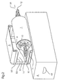
- Fig. 1 to 4 refers to a preferred embodiment of the inventive device for manually replacing and transporting a roller of a duplicating device.
- the device is in this case provided on a fixing / heating roller of a fixing unit F, wherein the fixing unit is arranged in a duplicating device, not shown, of known type, such as a copier.
- inventive device can also be used in other devices such as printers, image transfer units, photo printers with fuser units and sheet / belt conveyors or in sheet sorter units with sheet transport units; and that the rolls may be in the form of pressure, image transfer or sheet feed rolls.
- the fixing unit F shown in FIG. 1 is shown in a position laterally withdrawn from the copying machine on a carriage, not shown, and in an open upper position, with its fixing roller 1 in an upper position pivoted about a pivot axis Z by means of its upper chassis part.
- the fixing unit F in this case has the fixing roller 1 in the upper chassis part and a pressure roller 2 in the lower chassis part in a pair of rollers for passing and conveying a sheet or tape-shaped recording medium S, which in the closed position of the fixing in an abutting, axis-parallel arrangement their axial ends in bearings L1; L2; L3; L4 of the chassis parts are rotatably operable stored.
- the fixing roller 1 is provided with carrying means T1, T2, each having conventional pivot bearings, not shown, in which the fixing roller is freely rotatable about its center axis X1. Furthermore, the fixing roller 1 is equipped for the purpose of heating with a centrally mounted in her heating lamp H.
- the fixing unit F has at the bearing points L1, L2 in the upper chassis part manually operable means 3 for releasing the fixing roller 1 in their bearings for the purpose of removing these from their and / or insertion of these in their bearings.
- the roller has, as shown in Figures 1 to 4, at its two axial ends in each case a carrying handle T1, T2 as a support means, by means of which the roller arranged at the bearing points L1, L2 of the device, radially from the outer periphery to Center axis Y1 of the bearing points extending, substantially slot-shaped openings feasible, radially inserted into the bearings and can be removed from them.
- a separate protective container 5 is provided, which can be turned over and slipped over the roller 1 or fixing roller 1 released in the device and its carrying means T1, T2; the roller 1 is removable with the attached protective container 5 by means of their projecting from the protective container support means T1, T2 from the bearing points L1, L2 of the device and / or used in this.
- the protective container 5 has a substantially U-shaped cross-sectional profile, the inner cavity 1 for receiving the fixing roller 1 has a diameter which is greater than that of an outer diameter of the roller, such that when placed on the support means of the roller protective container no contact between the Protective container or its inner walls and the roller takes place.
- the protective container 5 as shown in Fig. 1 and 2, recesses 52 in its container wall 53 for receiving the support means T1, T2 of the fixing roller 1, whose clear, inner width relative to an associated outer diameter of the support means is so predetermined, the the protective container with its recesses on the carrying means can be arranged by clamping.
- the carrying handles T1, T2 of the carrying means are in this case arranged centrically to the axial center axis X1 at the ends of the fixing roller 1; and protrude the handles of the roller on the bearings L1, L2 of the device or the fixing unit F and on the protective container 5 axially.
- the carrying handles T1, T2 are in this case in the form of substantially angular handles or eyelets.
- Carrying handles designed as round or oval handles, eyelets or knobs.
- the protective container 5 has at its two ends or axially arranged side walls 53 each substantially slot-shaped recesses 52 for receiving the arranged at the axial ends of the roller 1
- the clear inner width of the recesses 52 is adjusted relative to the associated outer diameters of the centering / guiding / holding means 11 such that the protective container 5 with its side walls 53 and recesses 52 can be arranged thereon in a clamping manner.
- the slot-shaped recesses 52 are arranged for the means 11 on the side walls 53 of the protective container 5 centrally to the axial center axis of the inner cavity 51 of the U-shaped protective container; and have the recesses and the inner cavity 51 for attaching and removing the protective container to / from the fixing roller 1 same radial orientations.
- the protective container 5 also consists of a resilient, thermally resistant and insulating plastic material.
- the two handles T1, T2 of the fixing roller 1 means 10 for axially and radially centering, guiding and holding the roller 1 in their bearings L1, L2 in the device or in the fixing unit F; and on the other hand have means 11 for axially and radially centering, guiding and holding the protective container 5 on the roller 1 or on the carrying means T1, T2.
- the means 10; 11 1 for axial and radial centering, guiding and holding the fixing roller 1 in the bearing points L1, L2 of the fixing unit F and in the recesses 52 of the protective container 5 are summarized and integrally formed on the carrying handles T1, T2 arranged.
- the means 10, 11 are designed in the form of concentric around the center axis X1 of the fixing roller 1 arranged annular discs, wherein in each case a disc in the region of each axial end of the roller 1 and is arranged spaced therefrom.
- the two means 10 for centering, guiding and holding the fixing roller 1 in the bearing points L1, L2 are designed as substantially circular annular discs, which in inserting the fixing roller in the bearings L1, L2 in each case an annular circumferential groove (not shown) of the bearings be introduced.
- the carrying handles T1, T2 are thereby introduced into radially extending slot-shaped recesses or openings of the bearing points, so that they are secured against rotation and only the fixing roller 1 is in its in the carrying means L1, L2 pivot bearings, e.g. can rotate freely in conventional ball bearings.
- the two means 11 for centering, guiding and holding the protective container 5 are arranged as a rectangular area on the annular discs, which projects radially outwards, away from the bearing points L1, L2 and along the slot-shaped guides of the bearings, so that after releasing the fixing roller 1 in their bearing points L1, L2 by a release / locking lever 30 of the means 3, the protective container 5 by means of its grooves in the recesses 52 of the side walls 53 on this rectangular portion 11 of the two annular discs of the support means T1, T2 can be plugged.
- a transport container 6 For transporting the fixing roller 1, as shown in Fig. 2 to 4, a transport container 6 is provided with two handles 63 on side walls, in which the fitted with a fixing roller protective container 5 is manually inserted and removed, wherein in the transport container means 61; Position assurance of the protective container and the roller are arranged.
- arranged at the bottom of the transport container means 62 for securing the position of the fixing roller 1 on the carrying handles T1, T2 of the roller and act against the disposed on a longitudinal wall of the transport container position assurance means 61 of the protective container 5.
- the means 61, 62 for securing the position of the Roller and the protective container are resiliently formed, wherein the means 62 are designed in the form of a spring clip and the means 61 in the form of retaining bolts on which eyes of the protective container 5 can be plugged.
- the transport container 6 has a plurality of position securing means 61, 62 for receiving a plurality of rollers 1 with protective container 5.
Landscapes
- Physics & Mathematics (AREA)
- General Physics & Mathematics (AREA)
- Fixing For Electrophotography (AREA)
- Electrophotography Configuration And Component (AREA)
- Electrostatic Charge, Transfer And Separation In Electrography (AREA)
Claims (10)
- Dispositif de remplacement manuel et de transport d'un tambour (1) d'un moyen de reproduction ou d'une imprimante électro-photographique, ledit tambour étant équipé de poignées, une enceinte de protection (5) étant prévue qui peut être déposée sur le tambour (1) libéré dans le moyen de reproduction et sur les poignées (T1, T2) du tambour (1), ce dernier pouvant être retiré, avec son enceinte de protection (5), du moyen de reproduction à l'aide des poignées (T1, T2) dépassant hors de l'enceinte de protection et remis dans ce dernier, ladite enceinte de protection (5) ayant sensiblement un profil en U, le vide (51) de l'enceinte de protection servant à protéger le tambour (1) ayant un diamètre supérieur au diamètre extérieur dudit tambour de façon à exclure tout contact entre l'enceinte de protection et le tambour lorsque l'enceinte de protection est posée sur les poignées du tambour, ladite enceinte de protection (5) comprenant des dégagements (52) ménagés dans sa paroi (53) pour intégrer les poignées (T1, T2) du tambour, le diamètre intérieur desdits dégagements étant défini par rapport au diamètre extérieur des poignées correspondantes de façon à coincer les dégagements sur les poignées lors de la dépose de l'enceinte de protection,
caractérisé en ce que
le tambour (1) est un tambour chaud de fixation/chauffage et
qu'un conteneur de transport (6) est prévu pour l'enceinte de protection (5) équipée d'un tambour (1), l'enceinte de protection (5) pouvant être placée manuellement dans ledit conteneur de transport (6), des moyens d'immobilisation (61, 62) de l'enceinte de protection et du tambour étant disposés dans ledit conteneur, des moyens d'immobilisation (62) du tambour (1) étant en contact avec les poignées (T1, T2) et en appui contre les moyens d'immobilisation (61) de l'enceinte de protection (5), les moyens d'immobilisation (61, 62) du tambour et de l'enceinte de protection étant réalisés sous forme élastique. - Dispositif selon la revendication 1,
caractérisé en ce que
le tambour (1) possédant à ses deux extrémités axiales des poignées (T1, T2) servant de moyens de transport par lesquelles le tambour peut être guidé dans des orifices de forme sensiblement longitudinale disposés au niveau des points d'appui (L1, L2) du dispositif et orientés, dans le sens radial, de la circonférence extérieure vers l'axe central (Y1) peut être introduit dans le sens radial au niveau des points d'appui et extrait de ces derniers. - Dispositif selon la revendication 2,
caractérisé en ce que
les poignées (T1, T2) sont disposées dans le sens central par rapport à l'axe central (X1) au niveau des extrémités du tambour (1) ; et que lesdites poignées du tambour dépassent l'extrémité axiale du dispositif au niveau des points d'appui (L1, L2). - Dispositif selon la revendication 3,
caractérisé en ce que
les deux poignées (T1, T2) du tambour (1) comprennent des moyens (10) de centrage, de guidage et de maintien du tambour dans les sens axial et radial au niveau de leurs points d'appui (L1, L2) dans le dispositif ; que les deux poignées du tambour (1) comprennent des moyens (11) de centrage, de guidage et de maintien de l'enceinte de protection (5) sur le tambour dans les sens axial et radial ; et que les poignées (T1, T2) ont une forme se rapprochant sensiblement à celle d'anses, d'oeillets ou de pommeaux rectangulaires, ronds ou ovales. - Dispositif selon la revendication 4,
caractérisé en ce que
les moyens (10, 11) de centrage et de guidage du tambour (1) dans les sens axial et radial sont regroupés au niveau des points d'appui (L1, L2) du dispositif et dans les dégagements (52) de l'enceinte de protection (5) et qu'ils sont réalisés sous forme monobloc au niveau des poignées. - Moyen de reproduction et/ou imprimante électro-photographique avec un tambour échangeable selon l'une des revendications 2 à 5.
- Dispositif selon la revendication 5,
caractérisé en ce que
l'enceinte de protection (5) comprend, au niveau de ses deux parois latérales (53) disposées dans le sens axial, des dégagements (52) de forme sensiblement longitudinale destinés à recevoir les moyens (11) de centrage/guidage des poignées (T1, T2), lesdits moyens étant disposés aux extrémités axiales du tambour (1) ; que le diamètre intérieur des dégagements (52) par rapport aux diamètres extérieurs correspondants des moyens (11) de centrage/guidage est adapté de façon à coincer l'enceinte de protection (5) par ses parois latérales (53) sur eux lors de sa dépose. - Dispositif selon la revendication 7,
caractérisé en ce que
les dégagements (52) longitudinaux prévus pour les moyens (11) dans les parois latérales (53) de l'enceinte de protection (5) sont disposés de manière co-axiale par rapport à l'axe du vide de l'enceinte de protection à profil en U ; et que les dégagements et le vide sont orientés dans le même sens pour déposer l'enceinte de protection sur le tambour (1) et pour la retirer de ce dernier. - Dispositif selon la revendication 1,
caractérisé en ce
qu'il comprend plusieurs moyens d'immobilisation (61, 62) permettant de loger plusieurs tambours (1) dans leurs enceintes de protection (5) ; et que le conteneur de transport comprend deux poignées (63). - Dispositif selon la revendication 1,
caractérisé en ce que
l'enceinte de protection (5) est fabriquée en une matière plastique élastique à résistance thermique et isolante.
Applications Claiming Priority (2)
| Application Number | Priority Date | Filing Date | Title |
|---|---|---|---|
| DE10023715A DE10023715A1 (de) | 2000-05-17 | 2000-05-17 | Vorrichtung zum manuellen Austauschen und Transportieren einer Walze eines Vervielfältigungsgerätes |
| DE10023715 | 2000-05-17 |
Publications (3)
| Publication Number | Publication Date |
|---|---|
| EP1156397A2 EP1156397A2 (fr) | 2001-11-21 |
| EP1156397A3 EP1156397A3 (fr) | 2005-01-26 |
| EP1156397B1 true EP1156397B1 (fr) | 2007-07-25 |
Family
ID=7642088
Family Applications (1)
| Application Number | Title | Priority Date | Filing Date |
|---|---|---|---|
| EP01110024A Expired - Lifetime EP1156397B1 (fr) | 2000-05-17 | 2001-04-26 | Dispositif pour changer et transporter manuellement un rouleau de chauffage d'un appareil de reproduction par exemple d'une imprimante électrophotographique |
Country Status (4)
| Country | Link |
|---|---|
| US (1) | US6490425B2 (fr) |
| EP (1) | EP1156397B1 (fr) |
| AT (1) | ATE368243T1 (fr) |
| DE (2) | DE10023715A1 (fr) |
Families Citing this family (2)
| Publication number | Priority date | Publication date | Assignee | Title |
|---|---|---|---|---|
| US6785493B2 (en) | 2002-07-11 | 2004-08-31 | Hewlett-Packard Development Company, L.P. | User-replaceable fuser cartridge for electrophotographic printing systems |
| JP5493921B2 (ja) * | 2010-01-29 | 2014-05-14 | 株式会社リコー | 定着装置のローラ交換補助具 |
Citations (1)
| Publication number | Priority date | Publication date | Assignee | Title |
|---|---|---|---|---|
| WO1993015446A1 (fr) * | 1992-01-31 | 1993-08-05 | Eastman Kodak Company | Fixateur et cartouche pour rouleau fixateur |
Family Cites Families (14)
| Publication number | Priority date | Publication date | Assignee | Title |
|---|---|---|---|---|
| US3888577A (en) * | 1973-02-12 | 1975-06-10 | Xerox Corp | Apparatus for packaging and subsequently installing a belt onto a roller assembly |
| JPS59111672A (ja) * | 1982-12-17 | 1984-06-27 | Fuji Electric Co Ltd | 電子写真用感光体の梱包方法 |
| US4888620A (en) * | 1986-01-17 | 1989-12-19 | Canon Kabushiki Kaisha | Process cartridge and image forming apparatus using the same |
| GB2189327A (en) * | 1986-04-15 | 1987-10-21 | Xerox Corp | Copier having readily replacable photoconductive member |
| JPS63146086A (ja) * | 1986-12-10 | 1988-06-18 | Toshiba Corp | 記録装置 |
| US5239349A (en) * | 1992-01-31 | 1993-08-24 | Eastman Kodak Company | Fuser and a fuser roller cartridge having fusing roller skive |
| JPH06186895A (ja) * | 1992-12-16 | 1994-07-08 | Ricoh Co Ltd | 梱包箱 |
| US5481350A (en) * | 1993-04-12 | 1996-01-02 | Ricoh Company, Ltd. | Heat roller fixing device divided into first and second frames and with positioning members of the first frame |
| US6249661B1 (en) * | 1993-12-08 | 2001-06-19 | Ricoh Company, Ltd. | Device for supporting an image carrier included in an image forming apparatus |
| DE4443764B4 (de) * | 1993-12-08 | 2004-09-30 | Ricoh Co., Ltd. | Anordnung zum Halten eines Bildträgers |
| US5842085A (en) * | 1996-07-09 | 1998-11-24 | Mita Industrial Co., Ltd. | Fixing device in an image forming machine having reduced thermal fatigue |
| US6048676A (en) * | 1997-12-04 | 2000-04-11 | Agfa-Gevaert | Light-tight package for a roll of light-sensitive material |
| US6285845B1 (en) * | 1999-05-11 | 2001-09-04 | Zih Corp. | Card cleaning device and method of use |
| US6295427B1 (en) * | 1999-12-29 | 2001-09-25 | Nex Press Solutions Llc | Protective container/installation fixture for image-recording/image-transfer drums |
-
2000
- 2000-05-17 DE DE10023715A patent/DE10023715A1/de not_active Withdrawn
-
2001
- 2001-04-26 EP EP01110024A patent/EP1156397B1/fr not_active Expired - Lifetime
- 2001-04-26 DE DE50112755T patent/DE50112755D1/de not_active Expired - Lifetime
- 2001-04-26 AT AT01110024T patent/ATE368243T1/de not_active IP Right Cessation
- 2001-05-07 US US09/850,513 patent/US6490425B2/en not_active Expired - Fee Related
Patent Citations (1)
| Publication number | Priority date | Publication date | Assignee | Title |
|---|---|---|---|---|
| WO1993015446A1 (fr) * | 1992-01-31 | 1993-08-05 | Eastman Kodak Company | Fixateur et cartouche pour rouleau fixateur |
Also Published As
| Publication number | Publication date |
|---|---|
| ATE368243T1 (de) | 2007-08-15 |
| EP1156397A3 (fr) | 2005-01-26 |
| DE10023715A1 (de) | 2001-11-22 |
| EP1156397A2 (fr) | 2001-11-21 |
| DE50112755D1 (de) | 2007-09-06 |
| US6490425B2 (en) | 2002-12-03 |
| US20020025189A1 (en) | 2002-02-28 |
Similar Documents
| Publication | Publication Date | Title |
|---|---|---|
| DE60216705T2 (de) | Einheit und elektrophotografischer Bilderzeugungsapparat | |
| DE3443036C2 (fr) | ||
| DE69904287T2 (de) | Bilderzeugungsgerät, Kartusche für photoempfindliches Element, und Entwicklerkartusche | |
| DE69809163T2 (de) | Bilderzeugungsgerät ausgestattet mit einer lösbaren Fixiervorrichtung | |
| DE3425953A1 (de) | Druckgeraet | |
| DE4123868A1 (de) | Papierrollenhaltevorrichtung | |
| DE69413935T2 (de) | Übertragungsbandkassette für einen Wärmeübertragungsdrucker | |
| DE69010710T2 (de) | Bilderzeugungsgerät. | |
| EP1156397B1 (fr) | Dispositif pour changer et transporter manuellement un rouleau de chauffage d'un appareil de reproduction par exemple d'une imprimante électrophotographique | |
| DE3614354C2 (fr) | ||
| DE4300939A1 (en) | Paper transport system for image prodn. unit esp. copier - has three rollers and three surface parts for closing three guide plates to make pressure contact so that paper can be transported and plates opened for paper release | |
| DE2817300C2 (de) | Elektrofotografisches Kopiergerät mit einer austauschbaren endlichen Fotoleiterbahn | |
| DE60121765T2 (de) | Farbfilmhalter und Farbfilmspule | |
| EP0280949B1 (fr) | Support de bobine pour le stockage intermédiaire de produits imprimés enroulés tels que journaux, revues et analogues | |
| EP1156396B1 (fr) | Dispositif pour changer manuellement un rouleau d'un appareil de reproduction | |
| DE3153658C2 (de) | Bildaufzeichnungsger{t | |
| DE69608149T2 (de) | Bilderzeugungsgerät mit einer Aufnahme für eine Rolle Bildempfangsmaterials | |
| DE4443764B4 (de) | Anordnung zum Halten eines Bildträgers | |
| EP0995596A1 (fr) | Dispositif et procédé pour la mise en oeuvre d'un changement de plaques en marche | |
| DE4204726A1 (de) | Aufzeichnungsvorrichtung | |
| DE10163419A1 (de) | Fixierer-Bandreinigungsbaugruppe für eine elektrofotografische Vorrichtung | |
| DE2653519B1 (de) | Reinigungseinrichtung fuer die Fixierwalze eines Druckfixierwalzenpaares in einem elektrostatischen Kopiergeraet | |
| DE3515610C1 (de) | Andrueckrolle fuer ein Etikettiergeraet | |
| DE2245573C3 (de) | Haltevorrichtung für eine Rolle von fotografischem Kopiermaterial | |
| DE3604915A1 (de) | Papierfuehrungsvorrichtung fuer einen drucker |
Legal Events
| Date | Code | Title | Description |
|---|---|---|---|
| PUAI | Public reference made under article 153(3) epc to a published international application that has entered the european phase |
Free format text: ORIGINAL CODE: 0009012 |
|
| AK | Designated contracting states |
Kind code of ref document: A2 Designated state(s): AT BE CH CY DE DK ES FI FR GB GR IE IT LI LU MC NL PT SE TR |
|
| AX | Request for extension of the european patent |
Free format text: AL;LT;LV;MK;RO;SI |
|
| RAP1 | Party data changed (applicant data changed or rights of an application transferred) |
Owner name: EASTMAN KODAK COMPANY |
|
| PUAL | Search report despatched |
Free format text: ORIGINAL CODE: 0009013 |
|
| AK | Designated contracting states |
Kind code of ref document: A3 Designated state(s): AT BE CH CY DE DK ES FI FR GB GR IE IT LI LU MC NL PT SE TR |
|
| AX | Request for extension of the european patent |
Extension state: AL LT LV MK RO SI |
|
| 17P | Request for examination filed |
Effective date: 20050604 |
|
| AKX | Designation fees paid |
Designated state(s): AT BE CH CY DE DK ES FI FR GB GR IE IT LI LU MC NL PT SE TR |
|
| GRAP | Despatch of communication of intention to grant a patent |
Free format text: ORIGINAL CODE: EPIDOSNIGR1 |
|
| RTI1 | Title (correction) |
Free format text: DEVICE FOR MANUALLY EXCHANGING AND TRANSPORTING A HEATING ROLL OF A REPRODUCTION APPARATUS FOR EXAMPLE AN ELECTROPHOTOGRAPHIC PRINTER |
|
| GRAS | Grant fee paid |
Free format text: ORIGINAL CODE: EPIDOSNIGR3 |
|
| GRAA | (expected) grant |
Free format text: ORIGINAL CODE: 0009210 |
|
| AK | Designated contracting states |
Kind code of ref document: B1 Designated state(s): AT BE CH CY DE DK ES FI FR GB GR IE IT LI LU MC NL PT SE TR |
|
| REG | Reference to a national code |
Ref country code: GB Ref legal event code: FG4D Free format text: NOT ENGLISH |
|
| RIN1 | Information on inventor provided before grant (corrected) |
Inventor name: SCHMIDT, PETER Inventor name: KONDAY, ANDREAS Inventor name: WEBER, MARKUS |
|
| GBT | Gb: translation of ep patent filed (gb section 77(6)(a)/1977) |
Effective date: 20070725 |
|
| REG | Reference to a national code |
Ref country code: CH Ref legal event code: EP |
|
| REG | Reference to a national code |
Ref country code: IE Ref legal event code: FG4D Free format text: LANGUAGE OF EP DOCUMENT: GERMAN |
|
| REF | Corresponds to: |
Ref document number: 50112755 Country of ref document: DE Date of ref document: 20070906 Kind code of ref document: P |
|
| PG25 | Lapsed in a contracting state [announced via postgrant information from national office to epo] |
Ref country code: FI Free format text: LAPSE BECAUSE OF FAILURE TO SUBMIT A TRANSLATION OF THE DESCRIPTION OR TO PAY THE FEE WITHIN THE PRESCRIBED TIME-LIMIT Effective date: 20070725 Ref country code: NL Free format text: LAPSE BECAUSE OF FAILURE TO SUBMIT A TRANSLATION OF THE DESCRIPTION OR TO PAY THE FEE WITHIN THE PRESCRIBED TIME-LIMIT Effective date: 20070725 Ref country code: ES Free format text: LAPSE BECAUSE OF FAILURE TO SUBMIT A TRANSLATION OF THE DESCRIPTION OR TO PAY THE FEE WITHIN THE PRESCRIBED TIME-LIMIT Effective date: 20071105 Ref country code: PT Free format text: LAPSE BECAUSE OF FAILURE TO SUBMIT A TRANSLATION OF THE DESCRIPTION OR TO PAY THE FEE WITHIN THE PRESCRIBED TIME-LIMIT Effective date: 20071226 |
|
| NLV1 | Nl: lapsed or annulled due to failure to fulfill the requirements of art. 29p and 29m of the patents act | ||
| REG | Reference to a national code |
Ref country code: IE Ref legal event code: FD4D |
|
| EN | Fr: translation not filed | ||
| PG25 | Lapsed in a contracting state [announced via postgrant information from national office to epo] |
Ref country code: GR Free format text: LAPSE BECAUSE OF FAILURE TO SUBMIT A TRANSLATION OF THE DESCRIPTION OR TO PAY THE FEE WITHIN THE PRESCRIBED TIME-LIMIT Effective date: 20071026 Ref country code: DK Free format text: LAPSE BECAUSE OF FAILURE TO SUBMIT A TRANSLATION OF THE DESCRIPTION OR TO PAY THE FEE WITHIN THE PRESCRIBED TIME-LIMIT Effective date: 20070725 |
|
| PG25 | Lapsed in a contracting state [announced via postgrant information from national office to epo] |
Ref country code: IE Free format text: LAPSE BECAUSE OF FAILURE TO SUBMIT A TRANSLATION OF THE DESCRIPTION OR TO PAY THE FEE WITHIN THE PRESCRIBED TIME-LIMIT Effective date: 20070725 |
|
| PLBE | No opposition filed within time limit |
Free format text: ORIGINAL CODE: 0009261 |
|
| STAA | Information on the status of an ep patent application or granted ep patent |
Free format text: STATUS: NO OPPOSITION FILED WITHIN TIME LIMIT |
|
| PG25 | Lapsed in a contracting state [announced via postgrant information from national office to epo] |
Ref country code: SE Free format text: LAPSE BECAUSE OF FAILURE TO SUBMIT A TRANSLATION OF THE DESCRIPTION OR TO PAY THE FEE WITHIN THE PRESCRIBED TIME-LIMIT Effective date: 20071025 |
|
| 26N | No opposition filed |
Effective date: 20080428 |
|
| PG25 | Lapsed in a contracting state [announced via postgrant information from national office to epo] |
Ref country code: FR Free format text: LAPSE BECAUSE OF FAILURE TO SUBMIT A TRANSLATION OF THE DESCRIPTION OR TO PAY THE FEE WITHIN THE PRESCRIBED TIME-LIMIT Effective date: 20080321 |
|
| BERE | Be: lapsed |
Owner name: EASTMAN KODAK CY Effective date: 20080430 |
|
| PG25 | Lapsed in a contracting state [announced via postgrant information from national office to epo] |
Ref country code: MC Free format text: LAPSE BECAUSE OF NON-PAYMENT OF DUE FEES Effective date: 20080430 |
|
| REG | Reference to a national code |
Ref country code: CH Ref legal event code: PL |
|
| PG25 | Lapsed in a contracting state [announced via postgrant information from national office to epo] |
Ref country code: LI Free format text: LAPSE BECAUSE OF NON-PAYMENT OF DUE FEES Effective date: 20080430 Ref country code: CH Free format text: LAPSE BECAUSE OF NON-PAYMENT OF DUE FEES Effective date: 20080430 |
|
| PG25 | Lapsed in a contracting state [announced via postgrant information from national office to epo] |
Ref country code: BE Free format text: LAPSE BECAUSE OF NON-PAYMENT OF DUE FEES Effective date: 20080430 |
|
| PG25 | Lapsed in a contracting state [announced via postgrant information from national office to epo] |
Ref country code: CY Free format text: LAPSE BECAUSE OF FAILURE TO SUBMIT A TRANSLATION OF THE DESCRIPTION OR TO PAY THE FEE WITHIN THE PRESCRIBED TIME-LIMIT Effective date: 20070725 |
|
| PG25 | Lapsed in a contracting state [announced via postgrant information from national office to epo] |
Ref country code: AT Free format text: LAPSE BECAUSE OF NON-PAYMENT OF DUE FEES Effective date: 20080426 |
|
| PG25 | Lapsed in a contracting state [announced via postgrant information from national office to epo] |
Ref country code: LU Free format text: LAPSE BECAUSE OF NON-PAYMENT OF DUE FEES Effective date: 20080426 |
|
| PG25 | Lapsed in a contracting state [announced via postgrant information from national office to epo] |
Ref country code: TR Free format text: LAPSE BECAUSE OF FAILURE TO SUBMIT A TRANSLATION OF THE DESCRIPTION OR TO PAY THE FEE WITHIN THE PRESCRIBED TIME-LIMIT Effective date: 20070725 |
|
| PG25 | Lapsed in a contracting state [announced via postgrant information from national office to epo] |
Ref country code: IT Free format text: LAPSE BECAUSE OF NON-PAYMENT OF DUE FEES Effective date: 20080430 |
|
| PGFP | Annual fee paid to national office [announced via postgrant information from national office to epo] |
Ref country code: GB Payment date: 20130326 Year of fee payment: 13 |
|
| PGFP | Annual fee paid to national office [announced via postgrant information from national office to epo] |
Ref country code: DE Payment date: 20130430 Year of fee payment: 13 |
|
| REG | Reference to a national code |
Ref country code: DE Ref legal event code: R119 Ref document number: 50112755 Country of ref document: DE |
|
| GBPC | Gb: european patent ceased through non-payment of renewal fee |
Effective date: 20140426 |
|
| PG25 | Lapsed in a contracting state [announced via postgrant information from national office to epo] |
Ref country code: GB Free format text: LAPSE BECAUSE OF NON-PAYMENT OF DUE FEES Effective date: 20140426 Ref country code: DE Free format text: LAPSE BECAUSE OF NON-PAYMENT OF DUE FEES Effective date: 20141101 |
|
| REG | Reference to a national code |
Ref country code: DE Ref legal event code: R119 Ref document number: 50112755 Country of ref document: DE Effective date: 20141101 |