EP1156397B1 - Device for manually exchanging and transporting a heating roll of a reproduction apparatus for example an electrophotographic printer - Google Patents
Device for manually exchanging and transporting a heating roll of a reproduction apparatus for example an electrophotographic printer Download PDFInfo
- Publication number
- EP1156397B1 EP1156397B1 EP01110024A EP01110024A EP1156397B1 EP 1156397 B1 EP1156397 B1 EP 1156397B1 EP 01110024 A EP01110024 A EP 01110024A EP 01110024 A EP01110024 A EP 01110024A EP 1156397 B1 EP1156397 B1 EP 1156397B1
- Authority
- EP
- European Patent Office
- Prior art keywords
- roller
- protective container
- carrying
- container
- cutouts
- Prior art date
- Legal status (The legal status is an assumption and is not a legal conclusion. Google has not performed a legal analysis and makes no representation as to the accuracy of the status listed.)
- Expired - Lifetime
Links
- 238000010438 heat treatment Methods 0.000 title description 18
- 230000001681 protective effect Effects 0.000 claims abstract description 76
- 239000000463 material Substances 0.000 claims description 2
- 230000004308 accommodation Effects 0.000 claims 4
- 239000011796 hollow space material Substances 0.000 claims 3
- 238000003780 insertion Methods 0.000 description 3
- 230000037431 insertion Effects 0.000 description 3
- 230000006378 damage Effects 0.000 description 2
- 208000027418 Wounds and injury Diseases 0.000 description 1
- 230000001419 dependent effect Effects 0.000 description 1
- 239000011888 foil Substances 0.000 description 1
- 208000014674 injury Diseases 0.000 description 1
- 210000003127 knee Anatomy 0.000 description 1
- 210000002414 leg Anatomy 0.000 description 1
Images


Classifications
-
- G—PHYSICS
- G03—PHOTOGRAPHY; CINEMATOGRAPHY; ANALOGOUS TECHNIQUES USING WAVES OTHER THAN OPTICAL WAVES; ELECTROGRAPHY; HOLOGRAPHY
- G03G—ELECTROGRAPHY; ELECTROPHOTOGRAPHY; MAGNETOGRAPHY
- G03G15/00—Apparatus for electrographic processes using a charge pattern
- G03G15/20—Apparatus for electrographic processes using a charge pattern for fixing, e.g. by using heat
- G03G15/2003—Apparatus for electrographic processes using a charge pattern for fixing, e.g. by using heat using heat
- G03G15/2014—Apparatus for electrographic processes using a charge pattern for fixing, e.g. by using heat using heat using contact heat
- G03G15/2064—Apparatus for electrographic processes using a charge pattern for fixing, e.g. by using heat using heat using contact heat combined with pressure
-
- G—PHYSICS
- G03—PHOTOGRAPHY; CINEMATOGRAPHY; ANALOGOUS TECHNIQUES USING WAVES OTHER THAN OPTICAL WAVES; ELECTROGRAPHY; HOLOGRAPHY
- G03G—ELECTROGRAPHY; ELECTROPHOTOGRAPHY; MAGNETOGRAPHY
- G03G2221/00—Processes not provided for by group G03G2215/00, e.g. cleaning or residual charge elimination
- G03G2221/16—Mechanical means for facilitating the maintenance of the apparatus, e.g. modular arrangements and complete machine concepts
- G03G2221/1639—Mechanical means for facilitating the maintenance of the apparatus, e.g. modular arrangements and complete machine concepts for the fixing unit
-
- G—PHYSICS
- G03—PHOTOGRAPHY; CINEMATOGRAPHY; ANALOGOUS TECHNIQUES USING WAVES OTHER THAN OPTICAL WAVES; ELECTROGRAPHY; HOLOGRAPHY
- G03G—ELECTROGRAPHY; ELECTROPHOTOGRAPHY; MAGNETOGRAPHY
- G03G2221/00—Processes not provided for by group G03G2215/00, e.g. cleaning or residual charge elimination
- G03G2221/16—Mechanical means for facilitating the maintenance of the apparatus, e.g. modular arrangements and complete machine concepts
- G03G2221/18—Cartridge systems
Definitions
- the invention relates to a device for the manual replacement and transport of a roller of a duplicator or an electrophotographic printer.
- rollers for passing and conveying a sheet- or tape-shaped, toner image-carrying recording medium, which are rotatably operable in an abutting, axis-parallel arrangement in bearings of the device, mounted with their axial ends, and on the other hand manually operable means for releasing the rollers in their bearings and for separating the rollers in the radial direction for the purpose of removal from and insertion are arranged in their bearings.
- the EP-0 000 631-B1 discloses a copier of the type mentioned.
- the fixing / heating roller also has for its replacement and carrying a support means in the form of a single U-shaped handle, which is centrally located between the axial ends of the fixing / heating roller and radially to the center axis of the roller rigidly mounted on a U-shaped support frame ,
- the U-shaped holding frame has at its free U-leg ends in each case a bearing for one of the axial ends of the roller, in which it is freely rotatable.
- the holding frame has cube-shaped outside on its free U-leg ends, rigidly connected to the leg ends separate bearing pads, by means of which the fixing / heating roller can be inserted and removed in U-shaped bearings of the fixing unit.
- Disadvantage of this disclosed embodiment is that when using large, heavy Fixier / Wienwalzen for the purpose of improving the fixing quality, replacement and carrying the fixing / heating roller without jamming and damage by means of a single handle is difficult, and when removing a hot fixing / heating roller and storing in a transport container, this is not feasible without endangering the service person and damaging the roller.
- the invention is therefore an object of the invention to provide a device of the type mentioned, which does not have these disadvantages, but makes the implementation of a device customer service, especially replacing and transporting hot, heavy and large rolls safer and easier, and also has a simple, compact inexpensive structure.
- a protective container is provided, which is slipped over a released in the device roller and the support means, preferably attachable.
- the roller can then be removed, for example, with the attached protective container by means of their projecting from the protective container support means from the bearing points of the device or set in this again.
- the protective container has a substantially U-shaped cross-sectional profile
- the inner cavity for receiving a roller has a diameter which is greater than that of an outer diameter of the roller, such that when placed on the support means of the roller protective container no contact between the Protective container and the roller takes place; and the protective container recesses in its container wall for receiving the support means of the roller, whose clear inner width relative to an associated outer diameter of the support means such is predetermined that the protective container with its recesses on the carrying means can be arranged by clamping.
- a transport container in which the equipped with a roller protective container is manually inserted and removed, wherein means for securing the position of the protective container and the roller are arranged in the transport container.
- the invention also relates to a duplicating device or an electrophotographic printer according to the invention with an exchangeable roller having at its two axial ends in each case a carrying handle as a support means, by means of which the roller arranged at the bearing points of the device, extending radially from the outer periphery to the center axis of the bearing points , Guidable substantially slot-shaped openings, radially inserted into the bearings and can be removed from them. Because even in this way a safe removal of the roller from the copier without risk of injury is possible.
- the carrying handles are arranged centrally to the axial center axis at the ends of the roller; and protrude the handles of the roller over the bearing points of the device and a protective container axially out; and on the other hand, at least one of the two carrying handles of the roller means for axially and radially centering and guiding the roller in their bearings in the device; and at least one of the two handles of the roller (1) means (11; 21) for axially and radially centering and guiding a possibly provided protective container (5) on the roller.
- Fig. 1 to 4 refers to a preferred embodiment of the inventive device for manually replacing and transporting a roller of a duplicating device.
- the device is in this case provided on a fixing / heating roller of a fixing unit F, wherein the fixing unit is arranged in a duplicating device, not shown, of known type, such as a copier.
- inventive device can also be used in other devices such as printers, image transfer units, photo printers with fuser units and sheet / belt conveyors or in sheet sorter units with sheet transport units; and that the rolls may be in the form of pressure, image transfer or sheet feed rolls.
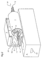
- the fixing unit F shown in FIG. 1 is shown in a position laterally withdrawn from the copying machine on a carriage, not shown, and in an open upper position, with its fixing roller 1 in an upper position pivoted about a pivot axis Z by means of its upper chassis part.
- the fixing unit F in this case has the fixing roller 1 in the upper chassis part and a pressure roller 2 in the lower chassis part in a pair of rollers for passing and conveying a sheet or tape-shaped recording medium S, which in the closed position of the fixing in an abutting, axis-parallel arrangement their axial ends in bearings L1; L2; L3; L4 of the chassis parts are rotatably operable stored.
- the fixing roller 1 is provided with carrying means T1, T2, each having conventional pivot bearings, not shown, in which the fixing roller is freely rotatable about its center axis X1. Furthermore, the fixing roller 1 is equipped for the purpose of heating with a centrally mounted in her heating lamp H.
- the fixing unit F has at the bearing points L1, L2 in the upper chassis part manually operable means 3 for releasing the fixing roller 1 in their bearings for the purpose of removing these from their and / or insertion of these in their bearings.
- the roller has, as shown in Figures 1 to 4, at its two axial ends in each case a carrying handle T1, T2 as a support means, by means of which the roller arranged at the bearing points L1, L2 of the device, radially from the outer periphery to Center axis Y1 of the bearing points extending, substantially slot-shaped openings feasible, radially inserted into the bearings and can be removed from them.
- a separate protective container 5 is provided, which can be turned over and slipped over the roller 1 or fixing roller 1 released in the device and its carrying means T1, T2; the roller 1 is removable with the attached protective container 5 by means of their projecting from the protective container support means T1, T2 from the bearing points L1, L2 of the device and / or used in this.
- the protective container 5 has a substantially U-shaped cross-sectional profile, the inner cavity 1 for receiving the fixing roller 1 has a diameter which is greater than that of an outer diameter of the roller, such that when placed on the support means of the roller protective container no contact between the Protective container or its inner walls and the roller takes place.
- the protective container 5 as shown in Fig. 1 and 2, recesses 52 in its container wall 53 for receiving the support means T1, T2 of the fixing roller 1, whose clear, inner width relative to an associated outer diameter of the support means is so predetermined, the the protective container with its recesses on the carrying means can be arranged by clamping.
- the carrying handles T1, T2 of the carrying means are in this case arranged centrically to the axial center axis X1 at the ends of the fixing roller 1; and protrude the handles of the roller on the bearings L1, L2 of the device or the fixing unit F and on the protective container 5 axially.
- the carrying handles T1, T2 are in this case in the form of substantially angular handles or eyelets.
- Carrying handles designed as round or oval handles, eyelets or knobs.
- the protective container 5 has at its two ends or axially arranged side walls 53 each substantially slot-shaped recesses 52 for receiving the arranged at the axial ends of the roller 1
- the clear inner width of the recesses 52 is adjusted relative to the associated outer diameters of the centering / guiding / holding means 11 such that the protective container 5 with its side walls 53 and recesses 52 can be arranged thereon in a clamping manner.
- the slot-shaped recesses 52 are arranged for the means 11 on the side walls 53 of the protective container 5 centrally to the axial center axis of the inner cavity 51 of the U-shaped protective container; and have the recesses and the inner cavity 51 for attaching and removing the protective container to / from the fixing roller 1 same radial orientations.
- the protective container 5 also consists of a resilient, thermally resistant and insulating plastic material.
- the two handles T1, T2 of the fixing roller 1 means 10 for axially and radially centering, guiding and holding the roller 1 in their bearings L1, L2 in the device or in the fixing unit F; and on the other hand have means 11 for axially and radially centering, guiding and holding the protective container 5 on the roller 1 or on the carrying means T1, T2.
- the means 10; 11 1 for axial and radial centering, guiding and holding the fixing roller 1 in the bearing points L1, L2 of the fixing unit F and in the recesses 52 of the protective container 5 are summarized and integrally formed on the carrying handles T1, T2 arranged.
- the means 10, 11 are designed in the form of concentric around the center axis X1 of the fixing roller 1 arranged annular discs, wherein in each case a disc in the region of each axial end of the roller 1 and is arranged spaced therefrom.
- the two means 10 for centering, guiding and holding the fixing roller 1 in the bearing points L1, L2 are designed as substantially circular annular discs, which in inserting the fixing roller in the bearings L1, L2 in each case an annular circumferential groove (not shown) of the bearings be introduced.
- the carrying handles T1, T2 are thereby introduced into radially extending slot-shaped recesses or openings of the bearing points, so that they are secured against rotation and only the fixing roller 1 is in its in the carrying means L1, L2 pivot bearings, e.g. can rotate freely in conventional ball bearings.
- the two means 11 for centering, guiding and holding the protective container 5 are arranged as a rectangular area on the annular discs, which projects radially outwards, away from the bearing points L1, L2 and along the slot-shaped guides of the bearings, so that after releasing the fixing roller 1 in their bearing points L1, L2 by a release / locking lever 30 of the means 3, the protective container 5 by means of its grooves in the recesses 52 of the side walls 53 on this rectangular portion 11 of the two annular discs of the support means T1, T2 can be plugged.
- a transport container 6 For transporting the fixing roller 1, as shown in Fig. 2 to 4, a transport container 6 is provided with two handles 63 on side walls, in which the fitted with a fixing roller protective container 5 is manually inserted and removed, wherein in the transport container means 61; Position assurance of the protective container and the roller are arranged.
- arranged at the bottom of the transport container means 62 for securing the position of the fixing roller 1 on the carrying handles T1, T2 of the roller and act against the disposed on a longitudinal wall of the transport container position assurance means 61 of the protective container 5.
- the means 61, 62 for securing the position of the Roller and the protective container are resiliently formed, wherein the means 62 are designed in the form of a spring clip and the means 61 in the form of retaining bolts on which eyes of the protective container 5 can be plugged.
- the transport container 6 has a plurality of position securing means 61, 62 for receiving a plurality of rollers 1 with protective container 5.
Landscapes
- Physics & Mathematics (AREA)
- General Physics & Mathematics (AREA)
- Fixing For Electrophotography (AREA)
- Electrophotography Configuration And Component (AREA)
- Electrostatic Charge, Transfer And Separation In Electrography (AREA)
Abstract
Description
Die Erfindung betrifft eine Vorrichtung zum manuellen Austauschen und Transportieren einer Walze eines Vervielfältigungsgerätes bzw. eines elektrophotographischen Druckers.The invention relates to a device for the manual replacement and transport of a roller of a duplicator or an electrophotographic printer.
Es sind Vervielfältigungsgeräte der eingangs genannten Art in Form von Kopierern bekannt, bei denen eine Walze zu Servicezwecken austauschbar und transportierbar angeordnet ist. Hierbei kann die Walze mit Tragemitteln ausgestattet sein, in denen sie frei um ihre Mittenachse drehend angeordnet ist. Das Kopiergerät seinerseits besitzt Walzen zum Hindurchführen und Fördern eines blatt- oder bandförmigen, tonerbildtragenden Aufzeichnungsmediums, die in einer aneinander anliegenden, achsenparallelen Anordnung in Lagerstellen des Gerätes rotierend betreibbar, mit ihren axialen Enden gelagert sind, und andererseits manuell betätigbare Mittel zum Freigeben der Walzen in ihren Lagerstellen sowie zum Trennen der Walzen in radialer Richtung zwecks Entnahme aus und Einsetzen in ihre Lagerstellen angeordnet sind.There are duplicating devices of the type mentioned in the form of copiers known in which a roller is arranged interchangeable and transportable for service purposes. Here, the roller may be equipped with carrying means in which it is arranged to rotate freely about its center axis. The copying machine in turn has rollers for passing and conveying a sheet- or tape-shaped, toner image-carrying recording medium, which are rotatably operable in an abutting, axis-parallel arrangement in bearings of the device, mounted with their axial ends, and on the other hand manually operable means for releasing the rollers in their bearings and for separating the rollers in the radial direction for the purpose of removal from and insertion are arranged in their bearings.
Die
Nachteil dieser offenbarten Ausführungsform ist, dass bei Einsatz großer, schwerer Fixier/Heizwalzen zwecks Verbesserung der Fixierqualität, ein Austauschen und Tragen der Fixier-/Heizwalze ohne ein Verkanten und Beschädigen mittels eines einzelnen Tragegriffes schwierig ist, und beim Entnehmen einer heißen Fixier-/Heizwalze und Ablegen in einen Transportbehälter, dies nicht ohne Gefährdung der Service-Person und Beschädigung der Walze machbar ist.Disadvantage of this disclosed embodiment is that when using large, heavy Fixier / Heizwalzen for the purpose of improving the fixing quality, replacement and carrying the fixing / heating roller without jamming and damage by means of a single handle is difficult, and when removing a hot fixing / heating roller and storing in a transport container, this is not feasible without endangering the service person and damaging the roller.
Weiterhin sind aus dem Stand der Technik bekannt:
-
DE-4443764 A1 -
JP-A-59111672 -
JP-A-06186895 -
WO93/15446
-
DE-4443764 A1 -
JP-A-59111672 -
JP-A-06186895 -
WO93 / 15446
Der Erfindung liegt daher die Aufgabe zugrunde, eine Vorrichtung der eingangs genannten Art zu schaffen, die diese genannten Nachteile nicht aufweist, sondern die die Durchführung eines Geräte-Kundendienstes, insbesondere ein Austauschen und Transportieren heißer, schwerer und großer Walzen sicherer und leichter macht, und zudem einen einfachen, kompakten kostengünstigen Aufbau aufweist.The invention is therefore an object of the invention to provide a device of the type mentioned, which does not have these disadvantages, but makes the implementation of a device customer service, especially replacing and transporting hot, heavy and large rolls safer and easier, and also has a simple, compact inexpensive structure.
Die Aufgabe wird mit einer Vorrichtung nach Anspruch 1 erfindungsgemäß dadurch gelöst, dass ein Schutzbehälter vorgesehen ist, der über eine im Gerät freigegebene Walze und deren Tragemittel stülpbar, vorzugsweise aufsteckbar ist. Die Walze kann dann beispielsweise mit dem aufgesteckten Schutzbehälter mittels ihrer aus dem Schutzbehälter herausragenden Tragemittel aus den Lagerstellen des Gerätes entnommen bzw. in diese wieder gesetzt werden.The object is achieved with a device according to
In vorteilhafter Weise weist der Schutzbehälter ein im wesentlichen U-förmiges Querschnittsprofil auf, dessen Innenhohlraum zur Aufnahme einer Walze einen Durchmesser hat, der größer als der eines Außendurchmessers der Walze ist, derart, dass bei auf die Tragemittel der Walze aufgestecktem Schutzbehälter keine Berührung zwischen dem Schutzbehälter und der Walze stattfindet; und weist der Schutzbehälter Freisparungen in seiner Behälterwand zur Aufnahme der Tragemittel der Walze auf, deren lichte, innere Weite gegenüber einem zugeordneten Außendurchmesser der Tragemittel derart vorbestimmt ist, das der Schutzbehälter mit seinen Freisparungen auf den Tragemitteln klemmend anordenbar ist.Advantageously, the protective container has a substantially U-shaped cross-sectional profile, the inner cavity for receiving a roller has a diameter which is greater than that of an outer diameter of the roller, such that when placed on the support means of the roller protective container no contact between the Protective container and the roller takes place; and the protective container recesses in its container wall for receiving the support means of the roller, whose clear inner width relative to an associated outer diameter of the support means such is predetermined that the protective container with its recesses on the carrying means can be arranged by clamping.
Zweckmäßigerweise ist außerdem ein Transportbehälter vorgesehen, in den der mit einer Walze bestückte Schutzbehälter manuell einlegbar und entnehmbar ist, wobei im Transportbehälter Mittel zur Lagesicherung des Schutzbehälters und der Walze angeordnet sind.Conveniently, a transport container is also provided, in which the equipped with a roller protective container is manually inserted and removed, wherein means for securing the position of the protective container and the roller are arranged in the transport container.
Die Erfindung betrifft außerdem ein Vervielfältigungsgerät bzw. einen elektrophotographischen Drucker erfindungsgemäß mit einer austauschbaren Walze, die an ihren beiden axialen Enden jeweils einen Tragegriff als Tragemittel aufweist, mittels denen die Walze in an den Lagerstellen des Gerätes angeordneten, radial vom Außenumfang zur Mittenachse der Lagerstellen verlaufenden, im wesentlichen schlitzförmigen Öffnungen führbar, radial in die Lagerstellen einsetzbar und aus ihnen entnehmbar ist. Denn auch auf diese Weise ist ein sicheres Entnehmen der Walze aus dem Kopierer ohne Verletzungsgefahr möglich.The invention also relates to a duplicating device or an electrophotographic printer according to the invention with an exchangeable roller having at its two axial ends in each case a carrying handle as a support means, by means of which the roller arranged at the bearing points of the device, extending radially from the outer periphery to the center axis of the bearing points , Guidable substantially slot-shaped openings, radially inserted into the bearings and can be removed from them. Because even in this way a safe removal of the roller from the copier without risk of injury is possible.
In vorteilhafter Weise sind einerseits die Tragegriffe zentrisch zur axialen Mittenachse an den Enden der Walze angeordnet; und ragen die Tragegriffe der Walze über die Lagerstellen des Gerätes und über einen Schutzbehälter axial hinaus; und weist andererseits mindestens einer der beiden Tragegriffe der Walze Mittel zum axialen und radialen Zentrieren und Führen der Walze in ihren Lagerstellen im Gerät; und mindestens einer der beiden Tragegriffe der Walze (1) Mittel (11;21) zum axialen und radialen Zentrieren und Führen eines ggf. vorgesehenen Schutzbehälters (5) auf der Walze auf.Advantageously, on the one hand the carrying handles are arranged centrally to the axial center axis at the ends of the roller; and protrude the handles of the roller over the bearing points of the device and a protective container axially out; and on the other hand, at least one of the two carrying handles of the roller means for axially and radially centering and guiding the roller in their bearings in the device; and at least one of the two handles of the roller (1) means (11; 21) for axially and radially centering and guiding a possibly provided protective container (5) on the roller.
Die weiteren Merkmale und Vorteile sind der Beschreibung der in der Zeichnung dargestellten Ausführungsbeispiele der Erfindung sowie den weiteren Unteransprüchen zu entnehmen. Die Zeichnung zeigt in der
- Fig. 1
- die erfindungsgemäße Vorrichtung als Schutz- und Handhabungsbehälter an einer Fixier-/Heizwalze einer aus einem Vervielfältigungsgerät herausgezogenen und geöffneten Fixiereinheit in einer räumlichen Darstellung,
- Fig. 2
- die erfindungsgemäße Vorrichtung nach Fig. 1 mit einer aus der Fixiereinheit entnommenen, teilweise in den Schutzbehälter eingeschobenen Fixier/Heizwalze in einer vergrößerten räumlichen Darstellung oberhalb eines Transportbehälters,
- Fig. 3
- die erfindungsgemäße Vorrichtung nach Fig. 2 mit in den Schutzbehälter eingeschobener Fixier-/Heizwalze oberhalb eines Transportbehälters,
- Fig. 4
- die erfindungsgemäße Vorrichtung nach Fig. 3 mit in den Transportbehälter eingelegtem, eine Fixier-/Heizwalze enthaltenden Schutzbehälter in einer räumlichen Darstellung von oben.
- Fig. 1
- the device according to the invention as a protective and handling container on a fixing / heating roller of an extracted from a duplicating device and opened fixing unit in a spatial representation,
- Fig. 2
- 1 with a removed from the fixing unit, partially inserted into the protective container fixing / heating roller in an enlarged spatial representation above a transport container,
- Fig. 3
- 2 according to the invention with fixing / heating roller inserted into the protective container above a transport container,
- Fig. 4
- the inventive device of FIG. 3 with inserted into the transport container, a fixing / heat roller containing protective container in a three-dimensional view from above.
Die folgende Beschreibung nach Fig. 1 bis 4 bezieht sich auf eine bevorzugte Ausführungsform der erfindungsgemäßen Vorrichtung zum manuellen Austauschen und Transportieren einer Walze eines Vervielfältigungsgerätes.The following description of Fig. 1 to 4 refers to a preferred embodiment of the inventive device for manually replacing and transporting a roller of a duplicating device.
Die Vorrichtung ist hierbei an einer Fixier-/Heizwalze einer Fixiereinheit F vorgesehen, wobei die Fixiereinheit in einem nicht gezeigten Vervielfältigungsgerät bekannter Art, wie zum Beispiel einem Kopierer angeordnet ist.The device is in this case provided on a fixing / heating roller of a fixing unit F, wherein the fixing unit is arranged in a duplicating device, not shown, of known type, such as a copier.
Für einen auf diesem Fachgebiet tätigen Fachmann ist es dabei selbstverständlich, dass die erfinderische Vorrichtung auch in anderen Geräten, wie in Druckern, Bildtransfereinheiten, Photo-Printern mit Fixiereinheiten und Blatt-/Bandfördereinheiten oder in Blattsortier-Geräten mit Blattfördereinheiten einsetzbar ist; und dass die Walzen in Form von Anpress-, Bild-Transfer- oder Blatt-Förderwalzen ausgebildet sein können.It will be understood by one of ordinary skill in the art that the inventive device can also be used in other devices such as printers, image transfer units, photo printers with fuser units and sheet / belt conveyors or in sheet sorter units with sheet transport units; and that the rolls may be in the form of pressure, image transfer or sheet feed rolls.
Die in Fig. 1 gezeigte Fixiereinheit F ist in einer aus dem Kopiergerät auf einem nicht gezeigten Schlitten bekannter Art seitlich herausgezogenen Position und in einer geöffneten, mit ihrer Fixierwalze 1 in einer mittels ihres oberen Chassisteils um eine Schwenkachse Z geschwenkten oberen Stellung dargestellt,The fixing unit F shown in FIG. 1 is shown in a position laterally withdrawn from the copying machine on a carriage, not shown, and in an open upper position, with its
Die Fixiereinheit F weist hierbei die Fixierwalze 1 im oberen Chassisteil und eine Anpresswalze 2 im unteren Chassisteil in einer Walzenpaar-Anordnung zum Hindurchführen und Fördern eines blatt- oder bandförmigen Aufzeichnungsmediums S auf, die bei geschlossener Stellung der Fixiereinheit in einer aneinander anliegenden, achsenparallelen Anordnung mit ihren axialen Enden in Lagerstellen L1;L2;L3;L4 der Chassisteile rotierend betreibbar, gelagert sind.The fixing unit F in this case has the
Zum Verschwenken des oberen Chassisteils der Fixiereinheit bzw. zum Trennen der Walzen 1;2 in radialer Richtung in die Offenstellung der Fixiereinheit, zwecks Entnahme der Fixierwalze 1 aus ihren und/oder Einsetzen in ihre Lagerstellen L1;L2, sind manuell betätigbare Mittel 4 mit einer Kniehebeleinheit mit Handgriff bzw. mit Betätigungshebel 40 angeordnet.For pivoting the upper chassis part of the fixing unit or for separating the
Die Fixierwalze 1 ist mit Tragemitteln T1;T2 ausgestattet, die jeweils übliche, nicht gezeigte Drehlager aufweisen, in denen die Fixierwalze frei um ihre Mittenachse X1 drehbar gelagert ist. Des weiteren ist die Fixierwalze 1 zwecks ihrer Erwärmung mit einer zentrisch in ihr angebrachten Heizlampe H ausgestattet.The
Weiterhin hat die Fixiereinheit F an den Lagerstellen L1;L2 im oberen Chassisteil manuell betätigbare Mittel 3 zum Freigeben der Fixierwalze 1 in ihren Lagerstellen zwecks Entnahme dieser aus ihren und/oder zum Einsetzen dieser in ihre Lagerstellen.Furthermore, the fixing unit F has at the bearing points L1, L2 in the upper chassis part manually operable means 3 for releasing the
Die Walze weist, wie in Fig. 1 bis 4 gezeigt, an ihren beiden axialen Enden jeweils einen Tragegriff T1;T2 als Tragemittel auf, mittels denen die Walze in an den Lagerstellen L1;L2 des Gerätes angeordneten, radial vom Außenumfang zur Mittenachse Y1 der Lagerstellen verlaufenden, im wesentlichen schlitzförmigen Öffnungen führbar, radial in die Lagerstellen einsetzbar und aus ihnen entnehmbar ist.The roller has, as shown in Figures 1 to 4, at its two axial ends in each case a carrying handle T1, T2 as a support means, by means of which the roller arranged at the bearing points L1, L2 of the device, radially from the outer periphery to Center axis Y1 of the bearing points extending, substantially slot-shaped openings feasible, radially inserted into the bearings and can be removed from them.
Weiterhin ist ein separater Schutzbehälter 5 vorgesehen, der über die im Gerät freigegebene Walze 1 bzw. Fixierwalze 1 und deren Tragemittel T1;T2 stülpbar und aufsteckbar ist; die Walze 1 ist mit dem aufgesteckten Schutzbehälter 5 mittels ihrer aus dem Schutzbehälter herausragenden Tragemittel T1;T2 aus den Lagerstellen L1;L2 des Gerätes entnehmbar und/oder in diese einsetzbar.Furthermore, a separate
Der Schutzbehälter 5 weist ein im wesentlichen U-förmiges Querschnittsprofil auf, dessen Innenhohlraum 1 zur Aufnahme der Fixierwalze 1 einen Durchmesser hat, der größer als der eines Außendurchmessers der Walze ist, derart, dass bei auf die Tragemittel der Walze aufgestecktem Schutzbehälter keine Berührung zwischen dem Schutzbehälter bzw. deren Innenwände und der Walze stattfindet.The
Des weiteren weist der Schutzbehälter 5, wie in Fig. 1 und 2 gezeigt, Freisparungen 52 in seiner Behälterwand 53 zur Aufnahme der Tragemittel T1;T2 der Fixierwalze 1 auf, deren lichte, innere Weite gegenüber einem zugeordneten Außendurchmesser der Tragemittel derart vorbestimmt ist, das der Schutzbehälter mit seinen Freisparungen auf den Tragemitteln klemmend anordenbar ist.Furthermore, the
Die Tragegriffe T1;T2 der Tragemittel sind hierbei zentrisch zur axialen Mittenachse X1 an den Enden der Fixierwalze 1 angeordnet; und ragen die Tragegriffe der Walze über die Lagerstellen L1;L2 des Gerätes bzw. der Fixiereinheit F und über den Schutzbehälter 5 axial hinaus. Die Tragegriffe T1;T2 sind hierbei in Form von im wesentlichen eckigen Henkeln bzw. Ösen ausgebildet.The carrying handles T1, T2 of the carrying means are in this case arranged centrically to the axial center axis X1 at the ends of the
In einer alternativen, nicht gezeigten erfindungsgemäßen Ausführungsform sind die. Tragegriffe als runde oder ovale Henkel, Ösen oder Knäufe ausgebildet.In an alternative, not shown embodiment of the invention are the. Carrying handles designed as round or oval handles, eyelets or knobs.
Der Schutzbehälter 5 weist an seinen beiden Enden bzw. axial angeordneten Seitenwänden 53 jeweils im wesentlichen schlitzförmige Freisparungen 52 zur Aufnahme von den an den axialen Enden der Walze 1 angeordnetenThe
Zentrier- /Führungs-/Halte- Mitteln 11 der Tragegriffen T1;T2 auf. Die lichte innere Weite der Freisparungen 52 ist gegenüber den zugeordneten Außendurchmessern der Zentrier/Führungs-/Halte-Mittel 11 derart angepasst, das der Schutzbehälter 5 mit seinen Seitenwänden 53 bzw. Freisparungen 52 darauf klemmend anordenbar ist.Centering / guiding / holding means 11 of the handles T1, T2 on. The clear inner width of the
Hierbei sind die schlitzförmigen Freisparungen 52 für die Mittel 11 an den Seitenwänden 53 des Schutzbehälters 5 zentrisch zur axialen Mittenachse des Innenhohlraumes 51 des U-förmigen Schutzbehälters angeordnet; und weisen die Freisparungen und der Innenhohlraum 51 zum Aufstecken und Entnehmen des Schutzbehälters auf/von die/der Fixierwalze 1 gleiche radiale Ausrichtungen auf.Here, the slot-shaped
Der Schutzbehälter 5 besteht zudem aus einem federelastischen, thermisch beständigen und isolierenden Kunststoffmaterial.The
Wie in Fig. 1 bis 3 dargestellt, weisen einerseits die beiden Tragegriffe T1;T2 der Fixierwalze 1 Mittel 10 zum axialen und radialen Zentrieren, Führen und Halten der Walze 1 in ihren Lagerstellen L1;L2 im Gerät bzw. in der Fixiereinheit F auf; und weisen andererseits Mittel 11 zum axialen und radialen Zentrieren, Führen und Halten des Schutzbehälters 5 auf der Walze 1 bzw. auf den Tragemitteln T1;T2 auf.As shown in Figures 1 to 3, on the one hand the two handles T1, T2 of the fixing
Die Mittel 10; 11 1 zum axialen und radialen Zentrieren, Führen und Halten der Fixierwalze 1 in den Lagerstellen L1;L2 der Fixiereinheit F und in den Freisparungen 52 des Schutzbehälters 5 sind dabei zusammengefasst und einstückig ausgebildet an den Tragegriffen T1;T2 angeordnet.The means 10; 11 1 for axial and radial centering, guiding and holding the fixing
Die Mittel 10;11 sind in Form von konzentrisch um die Mittenachse X1 der Fixierwalze 1 angeordnete ringförmige Scheiben ausgeführt, wobei jeweils eine Scheibe im Bereich jeden axialen Endes der Walze 1 und zu diesen beabstandet angeordnet ist.The means 10, 11 are designed in the form of concentric around the center axis X1 of the fixing
Die beiden Mittel 10 zum Zentrieren, Führen und Halten der Fixierwalze 1 in den Lagerstellen L1;L2 sind als im wesentlichen kreisrunde Ringscheiben ausgeführt, die beim Einsetzen der Fixierwalze in die Lagerstellen L1;L2 in jeweils eine ringförmig umlaufende Nut (nicht dargestellt) der Lagerstellen eingeführt werden. Die Tragegriffe T1;T2 werden dabei in radial verlaufende schlitzförmige Aussparungen bzw. Öffnungen der Lagerstellen eingeführt, so dass sie gegen ein Verdrehen gesichert sind und nur die Fixierwalze 1 sich in ihren in den Tragemitteln L1;L2 enthaltenen Drehlagern, z.B. in üblichen Kugellagern frei drehen kann.The two means 10 for centering, guiding and holding the fixing
Die beiden Mittel 11 zum Zentrieren, Führen und Halten des Schutzbehälters 5 sind als rechteckiger Bereich an den Ringscheiben angeordnet, der radial nach außen, von den Lagerstellen L1;L2 weg und längs der schlitzförmigen Führungen der Lagerstellen ragt, so dass nach dem Freigeben der Fixierwalze 1 in ihren Lagerstellen L1;L2 durch einen Ent/Verriegelungshebel 30 der Mittel 3, der Schutzbehälter 5 mittels seiner Nuten in den Freisparungen 52 der Seitenwände 53 auf diesen rechteckigen Bereich 11 der beiden Ringscheiben der Tragemittel T1;T2 aufsteckbar ist.The two means 11 for centering, guiding and holding the
Zum Transportieren der Fixierwalze 1 ist, wie in Fig. 2 bis 4 gezeigt, ein Transportbehälter 6 mit zwei Handgriffen 63 an Seitenwänden vorgesehen, in den der mit einer Fixierwalze bestückte Schutzbehälter 5 manuell einlegbar und entnehmbar ist, wobei im Transportbehälter Mittel 61;62 zur Lagesicherung des Schutzbehälters und der Walze angeordnet sind.For transporting the fixing
Wie in Fig. 4 dargestellt, greifen die am Boden des Transportbehälters angeordneten Mittel 62 zur Lagesicherung der Fixierwalze 1 an den Tragegriffen T1;T2 der Walze an und wirken gegen die an einer Längswand des Transportbehälters angeordnete Lagesicherungs-Mittel 61 des Schutzbehälters 5. Die Mittel 61;62 zur Lagesicherung der Walze und des Schutzbehälters sind dabei federelastisch ausgebildet, wobei die Mittel 62 in Form eines Federbügels und die Mittel 61 in Form von Haltebolzen ausgeführt sind, auf denen Ösen des Schutzbehälters 5 aufsteckbar sind.As shown in Fig. 4, arranged at the bottom of the transport container means 62 for securing the position of the fixing
In einer nicht gezeigten alternativen Ausführungsform weist der Transportbehälter 6 mehrere Lagesicherungsmittel 61;62 zur Aufnahme mehrerer Walzen 1 mit Schutzbehälter 5 auf.In an alternative embodiment, not shown, the
- L1L1
- erste Lagerstelle/n für 1.Walze (Fixier-/Heizwalze) in Fixiereinheitfirst bearing point (s) for 1st roller (fixing / heating roller) in fixing unit
- L2L2
- zweite Lagerstelle/n für 1.Walze (Fixier-/Heizwalze) in FixiereinheitSecond bearing point (s) for 1st roller (fixing / heating roller) in fixing unit
- L3L3
- erste Lagerstelle/n für 2.Walze (Anpresswalze) in Fixiereinheitfirst bearing point (s) for 2nd roller (pressure roller) in fuser unit
- L4L4
- zweite Lagerstelle/n für 2.Walze (Anpresswalze) in FixiereinheitSecond bearing point (s) for 2nd roller (pressure roller) in fixing unit
- FF
- Fixiereinheitfuser
- HH
- Heizlampe der 1. WalzeHeating lamp of the 1st roller
- SS
- Aufzeichnungsmedium /Blatt oder Band (Papier, Folie etc.)Recording medium / sheet or tape (paper, foil, etc.)
- T1T1
- erster Tragegriff/e von Tragemittel der 1.Walzefirst carrying handle / s of carrying means of the 1st roller
- T2T2
- zweiter Tragegriff/e von Tragemittel der 1.Walzesecond carrying handle / s of carrying means of the 1st roller
- X1X1
- Mittenachse der 1.WalzeCenter axis of the 1st roller
- X2X2
- Mittenachse der 2.WalzeCenter axis of 2nd roll
- Y1Y1
- Mittenachse von Lagerstelle für 1.WalzeCenter axis of bearing point for 1st roll
- Y2Y2
- Mittenachse von Lagerstelle für 2.WalzeCenter axis of bearing point for 2nd roller
- ZZ
- Schwenkachse der oberen und unteren Chassisteile der FixiereinheitSwivel axis of the upper and lower chassis parts of the fuser unit
- 11
- erste/obere Walze (Fixier-/Heizwalze) der Fixiereinheitfirst / upper roller (fixing / heating roller) of the fixing unit
- 22
- zweite/untere Walze(Fixier-/Heizwalze) der Fixiereinheitsecond / lower roller (fixing / heating roller) of the fixing unit
- 33
- Mittel zum Freigeben (Ent/Verriegeln) der Walzen in den LagerstellenMeans for releasing (unlocking / locking) the rollers in the bearings
- 44
- Mittel zum radialen Trennen (Aneinanderpressen) der Walzen in der FixiereinheitMeans for radially separating (pressing together) the rollers in the fixing unit
- 55
- Schutzbehälter / Handhabungsbehälter zum Aufstecken auf die WalzenProtective container / handling container for mounting on the rollers
- 66
- Transportbehälter für die Walze/n mit SchutzbehälterTransport container for the roller / s with protective container
- 1010
- Mittel an Tragegriff/en der 1.Walze zum axialen/radialen Zentrieren/Führen der 1. Walze in Lagerstellen von FixiereinheitMeans to carrying handle (s) of the 1st roller for axial / radial centering / guiding the 1st roller into bearings of fixing unit
- 1111
- Mittel an Tragegriff/en der 1.Walze zum axialen/radialen Zentrieren/Führen des SchutzbehältersMeans to carrying handle / s the 1st roll for axial / radial centering / guiding the protective container
- 3030
- Ent/Verriegelungshebel der Freigabemittel an LagerstellenRelease / release lever of the release agent at bearings
- 4040
- Betätigungshebel der Trennmittel/Schwenkmittel für die WalzenOperating lever of the separating means / pivoting means for the rollers
- 5151
- Innenhohlraum des SchutzbehältersInner cavity of the protective container
- 5252
- Freisparung/en in Seitenwand/wände des SchutzbehältersCut-outs in side wall / walls of the protective container
- 5353
- Seitenwand/wände des SchutzbehältersSide wall / walls of the protective container
- 6161
- Lagesicherungsmittel für Schutzbehälter im TransportbehälterPosition securing means for protective containers in the transport container
- 6262
- Lagesicherungsmittel für Walze im TransportbehälterPosition securing means for roller in the transport container
- 6363
- Handgriff/e an TransportbehälterHandle / s to transport container
Claims (10)
- Device for manually exchanging and transporting a roller (1) of a duplicating apparatus or an electrographic printer, said roller being equipped with carrying means, and a protective container (5) being provided which can be put over a roller (1) released in the duplicating apparatus and over its carrying means (T1, T2), said roller (1), together with the protective container (5), being taken out of and set into the duplicating apparatus by means of said protective container's carrying means (T1, T2) projecting from the protective container, the protective container (5) having an essentially U-shaped cross-sectional profile, the interior hollow space (51) of said protective container for the accommodation of a roller (1) having a diameter which is greater than the outside diameter of the roller, in such a manner that, with the protective container fitted onto the carrying means of the roller, no contact takes place between the protective container and the roller, and the protective container (5) having cutouts (52) in its container wall (53) for the accommodation of the carrying means (T1, T") of the roller, said cutouts' clear, inside width being pre-specified with respect to an associate diameter of the carrying means in such a manner that the cutouts of the protective container can be snapped onto the carrying means,
characterized in that
the roller (1) is a hot fuser/fixer hot roller, and that, for the protective container (5) loaded with a roller (1), a transport container (6) is provided, into which the protective container (5) can be manually placed and in which means (61, 62) are provided for securing the protective container and the roller in place, and that means (62) are in contact with the carrying means (T1, T2) to secure the roller (1) in place and counteract the means (61) for securing the protective container (5) in place, and that the means (61, 62) for securing the roller and the protective container in place are designed in a spring-elastic manner. - Device as in Claim 1,
characterized in that
the roller (1) has, on each of its two axial ends, one carrying handle (T1; T2) as the carrying means which can be used to guide the roller in essentially slit-shaped openings, radially set the roller into the bearing sites, and remove said roller from the bearing sites, said openings being provided at the bearing sites (L1; L2) of the apparatus and extending radially from the exterior circumference toward the center axis (Y1) of said bearing sites. - Device as in Claim 2,
characterized in that
the carrying handles (T1; T2) are arranged centrically with respect to the axial center axis (X1) on the ends of the roller (1), and that the carrying handles of the roller project, in axial direction, beyond the bearing sites (L1; L2) of the apparatus. - Device as in Claim 3,
characterized in that
the two carrying handles (T1; T2) of the roller (1) comprise means (10) for axially and radially centering, guiding and holding the roller in its bearing sites (L1; L2) in the apparatus, that the two carrying handles of the roller (1) comprise means (11) for axially and radially centering, guiding and holding the protective container (5) on the roller, and that the carrying handles (T1; T2) are configured as essentially angular, round or oval handles, lugs or knobs. - Device as in Claim 4,
characterized in that
the means (10; 11) for axially and radially centering and guiding the roller (1) in the bearing sites (L1; L2) of the apparatus and in the cutouts (52) of the protective container (5) are combined and designed in one piece on the carrying handles. - Duplicating apparatus or electrophotographic printer with an exchangeable roller in accordance with one of the Claims 2 through 5.
- Device as in Claim 5,
characterized in that
the protective container (5) has, on each of its two axially arranged lateral walls (53), essentially slit-shaped cutouts (52) for the accommodation of centering/guide means (11) of the carrying handles (T1; T2) which means (11) are located on the axial ends of the roller (1), and that the clear, inside width of the cutouts (52) is adapted to the associate outside diameters of the centering/guide means (11) in such a manner that the lateral walls (53) of the protective container (5) can be snapped onto said cutouts. - Device as in Claim 7,
characterized in that
the slit-shaped cutouts (52) for the means (11) are provided on the lateral walls (53) of the protective container (5), centered with respect to the axial center axis of the interior hollow space of the U-shaped protective container, and that the cutouts and the interior hollow space are aligned in the same direction for fitting the protective container onto the roller (1) and for removing the protective container from said roller. - Device as in Claim 1,
characterized in that
transport container comprises several position-securing means (61; 62) for the accommodation of several rollers (1) with protective container (5), and that the transport container has two handles (63). - Device as in Claim 1,
characterized in that
the protective container (5) consists of a spring-elastic, thermally stable and insulated plastic material.
Applications Claiming Priority (2)
| Application Number | Priority Date | Filing Date | Title |
|---|---|---|---|
| DE10023715A DE10023715A1 (en) | 2000-05-17 | 2000-05-17 | Device for the manual exchange and transport of a roller of a duplicating device |
| DE10023715 | 2000-05-17 |
Publications (3)
| Publication Number | Publication Date |
|---|---|
| EP1156397A2 EP1156397A2 (en) | 2001-11-21 |
| EP1156397A3 EP1156397A3 (en) | 2005-01-26 |
| EP1156397B1 true EP1156397B1 (en) | 2007-07-25 |
Family
ID=7642088
Family Applications (1)
| Application Number | Title | Priority Date | Filing Date |
|---|---|---|---|
| EP01110024A Expired - Lifetime EP1156397B1 (en) | 2000-05-17 | 2001-04-26 | Device for manually exchanging and transporting a heating roll of a reproduction apparatus for example an electrophotographic printer |
Country Status (4)
| Country | Link |
|---|---|
| US (1) | US6490425B2 (en) |
| EP (1) | EP1156397B1 (en) |
| AT (1) | ATE368243T1 (en) |
| DE (2) | DE10023715A1 (en) |
Families Citing this family (2)
| Publication number | Priority date | Publication date | Assignee | Title |
|---|---|---|---|---|
| US6785493B2 (en) | 2002-07-11 | 2004-08-31 | Hewlett-Packard Development Company, L.P. | User-replaceable fuser cartridge for electrophotographic printing systems |
| JP5493921B2 (en) * | 2010-01-29 | 2014-05-14 | 株式会社リコー | Roller replacement aid for fixing device |
Citations (1)
| Publication number | Priority date | Publication date | Assignee | Title |
|---|---|---|---|---|
| WO1993015446A1 (en) * | 1992-01-31 | 1993-08-05 | Eastman Kodak Company | Fuser and fusing roller cartridge therefor |
Family Cites Families (14)
| Publication number | Priority date | Publication date | Assignee | Title |
|---|---|---|---|---|
| US3888577A (en) * | 1973-02-12 | 1975-06-10 | Xerox Corp | Apparatus for packaging and subsequently installing a belt onto a roller assembly |
| JPS59111672A (en) * | 1982-12-17 | 1984-06-27 | Fuji Electric Co Ltd | Packing method of photosensitive body for electrophotography |
| US4888620A (en) * | 1986-01-17 | 1989-12-19 | Canon Kabushiki Kaisha | Process cartridge and image forming apparatus using the same |
| GB2189327A (en) * | 1986-04-15 | 1987-10-21 | Xerox Corp | Copier having readily replacable photoconductive member |
| JPS63146086A (en) * | 1986-12-10 | 1988-06-18 | Toshiba Corp | Recorder |
| US5239349A (en) * | 1992-01-31 | 1993-08-24 | Eastman Kodak Company | Fuser and a fuser roller cartridge having fusing roller skive |
| JPH06186895A (en) * | 1992-12-16 | 1994-07-08 | Ricoh Co Ltd | Packing box |
| US5481350A (en) * | 1993-04-12 | 1996-01-02 | Ricoh Company, Ltd. | Heat roller fixing device divided into first and second frames and with positioning members of the first frame |
| US6249661B1 (en) * | 1993-12-08 | 2001-06-19 | Ricoh Company, Ltd. | Device for supporting an image carrier included in an image forming apparatus |
| DE4443764B4 (en) * | 1993-12-08 | 2004-09-30 | Ricoh Co., Ltd. | Arrangement for holding an image carrier |
| US5842085A (en) * | 1996-07-09 | 1998-11-24 | Mita Industrial Co., Ltd. | Fixing device in an image forming machine having reduced thermal fatigue |
| US6048676A (en) * | 1997-12-04 | 2000-04-11 | Agfa-Gevaert | Light-tight package for a roll of light-sensitive material |
| US6285845B1 (en) * | 1999-05-11 | 2001-09-04 | Zih Corp. | Card cleaning device and method of use |
| US6295427B1 (en) * | 1999-12-29 | 2001-09-25 | Nex Press Solutions Llc | Protective container/installation fixture for image-recording/image-transfer drums |
-
2000
- 2000-05-17 DE DE10023715A patent/DE10023715A1/en not_active Withdrawn
-
2001
- 2001-04-26 EP EP01110024A patent/EP1156397B1/en not_active Expired - Lifetime
- 2001-04-26 DE DE50112755T patent/DE50112755D1/en not_active Expired - Lifetime
- 2001-04-26 AT AT01110024T patent/ATE368243T1/en not_active IP Right Cessation
- 2001-05-07 US US09/850,513 patent/US6490425B2/en not_active Expired - Fee Related
Patent Citations (1)
| Publication number | Priority date | Publication date | Assignee | Title |
|---|---|---|---|---|
| WO1993015446A1 (en) * | 1992-01-31 | 1993-08-05 | Eastman Kodak Company | Fuser and fusing roller cartridge therefor |
Also Published As
| Publication number | Publication date |
|---|---|
| ATE368243T1 (en) | 2007-08-15 |
| EP1156397A3 (en) | 2005-01-26 |
| DE10023715A1 (en) | 2001-11-22 |
| EP1156397A2 (en) | 2001-11-21 |
| DE50112755D1 (en) | 2007-09-06 |
| US6490425B2 (en) | 2002-12-03 |
| US20020025189A1 (en) | 2002-02-28 |
Similar Documents
| Publication | Publication Date | Title |
|---|---|---|
| DE60216705T2 (en) | Unit and electrophotographic image forming apparatus | |
| DE3443036C2 (en) | ||
| DE69904287T2 (en) | Image forming apparatus, photosensitive element cartridge, and developer cartridge | |
| DE69809163T2 (en) | Imaging device equipped with a releasable fixing device | |
| DE3425953A1 (en) | PRINTING DEVICE | |
| DE4123868A1 (en) | PAPER ROLL HOLDING DEVICE | |
| DE69413935T2 (en) | Transfer tape cartridge for a heat transfer printer | |
| DE69010710T2 (en) | Imaging device. | |
| EP1156397B1 (en) | Device for manually exchanging and transporting a heating roll of a reproduction apparatus for example an electrophotographic printer | |
| DE3614354C2 (en) | ||
| DE4300939A1 (en) | Paper transport system for image prodn. unit esp. copier - has three rollers and three surface parts for closing three guide plates to make pressure contact so that paper can be transported and plates opened for paper release | |
| DE2817300C2 (en) | Electrophotographic copier with an exchangeable finite photoconductor track | |
| DE60121765T2 (en) | Color film holder and paint film spool | |
| EP0280949B1 (en) | Roll support for the intermediate storing of printed products such as newspapers, magazines and the like | |
| EP1156396B1 (en) | Device for manually exchanging a roll of a reproduction machine | |
| DE3153658C2 (en) | Image recorder | |
| DE69608149T2 (en) | Image forming apparatus with a holder for a roll of image receiving material | |
| DE4443764B4 (en) | Arrangement for holding an image carrier | |
| EP0995596A1 (en) | Device and method and for carrying out a flying printing plate exchange | |
| DE4204726A1 (en) | RECORDING DEVICE | |
| DE10163419A1 (en) | Fuser belt cleaning assembly for an electrophotographic device | |
| DE2653519B1 (en) | Cleaning device for the fixing roller of a pair of pressure fixing rollers in an electrostatic copier | |
| DE3515610C1 (en) | Pressure roller for a labeling device | |
| DE2245573C3 (en) | Holding device for a roll of photographic copy material | |
| DE3604915A1 (en) | Paper feed device for a printer |
Legal Events
| Date | Code | Title | Description |
|---|---|---|---|
| PUAI | Public reference made under article 153(3) epc to a published international application that has entered the european phase |
Free format text: ORIGINAL CODE: 0009012 |
|
| AK | Designated contracting states |
Kind code of ref document: A2 Designated state(s): AT BE CH CY DE DK ES FI FR GB GR IE IT LI LU MC NL PT SE TR |
|
| AX | Request for extension of the european patent |
Free format text: AL;LT;LV;MK;RO;SI |
|
| RAP1 | Party data changed (applicant data changed or rights of an application transferred) |
Owner name: EASTMAN KODAK COMPANY |
|
| PUAL | Search report despatched |
Free format text: ORIGINAL CODE: 0009013 |
|
| AK | Designated contracting states |
Kind code of ref document: A3 Designated state(s): AT BE CH CY DE DK ES FI FR GB GR IE IT LI LU MC NL PT SE TR |
|
| AX | Request for extension of the european patent |
Extension state: AL LT LV MK RO SI |
|
| 17P | Request for examination filed |
Effective date: 20050604 |
|
| AKX | Designation fees paid |
Designated state(s): AT BE CH CY DE DK ES FI FR GB GR IE IT LI LU MC NL PT SE TR |
|
| GRAP | Despatch of communication of intention to grant a patent |
Free format text: ORIGINAL CODE: EPIDOSNIGR1 |
|
| RTI1 | Title (correction) |
Free format text: DEVICE FOR MANUALLY EXCHANGING AND TRANSPORTING A HEATING ROLL OF A REPRODUCTION APPARATUS FOR EXAMPLE AN ELECTROPHOTOGRAPHIC PRINTER |
|
| GRAS | Grant fee paid |
Free format text: ORIGINAL CODE: EPIDOSNIGR3 |
|
| GRAA | (expected) grant |
Free format text: ORIGINAL CODE: 0009210 |
|
| AK | Designated contracting states |
Kind code of ref document: B1 Designated state(s): AT BE CH CY DE DK ES FI FR GB GR IE IT LI LU MC NL PT SE TR |
|
| REG | Reference to a national code |
Ref country code: GB Ref legal event code: FG4D Free format text: NOT ENGLISH |
|
| RIN1 | Information on inventor provided before grant (corrected) |
Inventor name: SCHMIDT, PETER Inventor name: KONDAY, ANDREAS Inventor name: WEBER, MARKUS |
|
| GBT | Gb: translation of ep patent filed (gb section 77(6)(a)/1977) |
Effective date: 20070725 |
|
| REG | Reference to a national code |
Ref country code: CH Ref legal event code: EP |
|
| REG | Reference to a national code |
Ref country code: IE Ref legal event code: FG4D Free format text: LANGUAGE OF EP DOCUMENT: GERMAN |
|
| REF | Corresponds to: |
Ref document number: 50112755 Country of ref document: DE Date of ref document: 20070906 Kind code of ref document: P |
|
| PG25 | Lapsed in a contracting state [announced via postgrant information from national office to epo] |
Ref country code: FI Free format text: LAPSE BECAUSE OF FAILURE TO SUBMIT A TRANSLATION OF THE DESCRIPTION OR TO PAY THE FEE WITHIN THE PRESCRIBED TIME-LIMIT Effective date: 20070725 Ref country code: NL Free format text: LAPSE BECAUSE OF FAILURE TO SUBMIT A TRANSLATION OF THE DESCRIPTION OR TO PAY THE FEE WITHIN THE PRESCRIBED TIME-LIMIT Effective date: 20070725 Ref country code: ES Free format text: LAPSE BECAUSE OF FAILURE TO SUBMIT A TRANSLATION OF THE DESCRIPTION OR TO PAY THE FEE WITHIN THE PRESCRIBED TIME-LIMIT Effective date: 20071105 Ref country code: PT Free format text: LAPSE BECAUSE OF FAILURE TO SUBMIT A TRANSLATION OF THE DESCRIPTION OR TO PAY THE FEE WITHIN THE PRESCRIBED TIME-LIMIT Effective date: 20071226 |
|
| NLV1 | Nl: lapsed or annulled due to failure to fulfill the requirements of art. 29p and 29m of the patents act | ||
| REG | Reference to a national code |
Ref country code: IE Ref legal event code: FD4D |
|
| EN | Fr: translation not filed | ||
| PG25 | Lapsed in a contracting state [announced via postgrant information from national office to epo] |
Ref country code: GR Free format text: LAPSE BECAUSE OF FAILURE TO SUBMIT A TRANSLATION OF THE DESCRIPTION OR TO PAY THE FEE WITHIN THE PRESCRIBED TIME-LIMIT Effective date: 20071026 Ref country code: DK Free format text: LAPSE BECAUSE OF FAILURE TO SUBMIT A TRANSLATION OF THE DESCRIPTION OR TO PAY THE FEE WITHIN THE PRESCRIBED TIME-LIMIT Effective date: 20070725 |
|
| PG25 | Lapsed in a contracting state [announced via postgrant information from national office to epo] |
Ref country code: IE Free format text: LAPSE BECAUSE OF FAILURE TO SUBMIT A TRANSLATION OF THE DESCRIPTION OR TO PAY THE FEE WITHIN THE PRESCRIBED TIME-LIMIT Effective date: 20070725 |
|
| PLBE | No opposition filed within time limit |
Free format text: ORIGINAL CODE: 0009261 |
|
| STAA | Information on the status of an ep patent application or granted ep patent |
Free format text: STATUS: NO OPPOSITION FILED WITHIN TIME LIMIT |
|
| PG25 | Lapsed in a contracting state [announced via postgrant information from national office to epo] |
Ref country code: SE Free format text: LAPSE BECAUSE OF FAILURE TO SUBMIT A TRANSLATION OF THE DESCRIPTION OR TO PAY THE FEE WITHIN THE PRESCRIBED TIME-LIMIT Effective date: 20071025 |
|
| 26N | No opposition filed |
Effective date: 20080428 |
|
| PG25 | Lapsed in a contracting state [announced via postgrant information from national office to epo] |
Ref country code: FR Free format text: LAPSE BECAUSE OF FAILURE TO SUBMIT A TRANSLATION OF THE DESCRIPTION OR TO PAY THE FEE WITHIN THE PRESCRIBED TIME-LIMIT Effective date: 20080321 |
|
| BERE | Be: lapsed |
Owner name: EASTMAN KODAK CY Effective date: 20080430 |
|
| PG25 | Lapsed in a contracting state [announced via postgrant information from national office to epo] |
Ref country code: MC Free format text: LAPSE BECAUSE OF NON-PAYMENT OF DUE FEES Effective date: 20080430 |
|
| REG | Reference to a national code |
Ref country code: CH Ref legal event code: PL |
|
| PG25 | Lapsed in a contracting state [announced via postgrant information from national office to epo] |
Ref country code: LI Free format text: LAPSE BECAUSE OF NON-PAYMENT OF DUE FEES Effective date: 20080430 Ref country code: CH Free format text: LAPSE BECAUSE OF NON-PAYMENT OF DUE FEES Effective date: 20080430 |
|
| PG25 | Lapsed in a contracting state [announced via postgrant information from national office to epo] |
Ref country code: BE Free format text: LAPSE BECAUSE OF NON-PAYMENT OF DUE FEES Effective date: 20080430 |
|
| PG25 | Lapsed in a contracting state [announced via postgrant information from national office to epo] |
Ref country code: CY Free format text: LAPSE BECAUSE OF FAILURE TO SUBMIT A TRANSLATION OF THE DESCRIPTION OR TO PAY THE FEE WITHIN THE PRESCRIBED TIME-LIMIT Effective date: 20070725 |
|
| PG25 | Lapsed in a contracting state [announced via postgrant information from national office to epo] |
Ref country code: AT Free format text: LAPSE BECAUSE OF NON-PAYMENT OF DUE FEES Effective date: 20080426 |
|
| PG25 | Lapsed in a contracting state [announced via postgrant information from national office to epo] |
Ref country code: LU Free format text: LAPSE BECAUSE OF NON-PAYMENT OF DUE FEES Effective date: 20080426 |
|
| PG25 | Lapsed in a contracting state [announced via postgrant information from national office to epo] |
Ref country code: TR Free format text: LAPSE BECAUSE OF FAILURE TO SUBMIT A TRANSLATION OF THE DESCRIPTION OR TO PAY THE FEE WITHIN THE PRESCRIBED TIME-LIMIT Effective date: 20070725 |
|
| PG25 | Lapsed in a contracting state [announced via postgrant information from national office to epo] |
Ref country code: IT Free format text: LAPSE BECAUSE OF NON-PAYMENT OF DUE FEES Effective date: 20080430 |
|
| PGFP | Annual fee paid to national office [announced via postgrant information from national office to epo] |
Ref country code: GB Payment date: 20130326 Year of fee payment: 13 |
|
| PGFP | Annual fee paid to national office [announced via postgrant information from national office to epo] |
Ref country code: DE Payment date: 20130430 Year of fee payment: 13 |
|
| REG | Reference to a national code |
Ref country code: DE Ref legal event code: R119 Ref document number: 50112755 Country of ref document: DE |
|
| GBPC | Gb: european patent ceased through non-payment of renewal fee |
Effective date: 20140426 |
|
| PG25 | Lapsed in a contracting state [announced via postgrant information from national office to epo] |
Ref country code: GB Free format text: LAPSE BECAUSE OF NON-PAYMENT OF DUE FEES Effective date: 20140426 Ref country code: DE Free format text: LAPSE BECAUSE OF NON-PAYMENT OF DUE FEES Effective date: 20141101 |
|
| REG | Reference to a national code |
Ref country code: DE Ref legal event code: R119 Ref document number: 50112755 Country of ref document: DE Effective date: 20141101 |