EP1156396A2 - Vorrichtung zum manuellen Austauschen einer Walze eines Viervielfältigungsgerätes - Google Patents
Vorrichtung zum manuellen Austauschen einer Walze eines Viervielfältigungsgerätes Download PDFInfo
- Publication number
- EP1156396A2 EP1156396A2 EP01109441A EP01109441A EP1156396A2 EP 1156396 A2 EP1156396 A2 EP 1156396A2 EP 01109441 A EP01109441 A EP 01109441A EP 01109441 A EP01109441 A EP 01109441A EP 1156396 A2 EP1156396 A2 EP 1156396A2
- Authority
- EP
- European Patent Office
- Prior art keywords
- roller
- rollers
- bearing points
- handles
- carrying handles
- Prior art date
- Legal status (The legal status is an assumption and is not a legal conclusion. Google has not performed a legal analysis and makes no representation as to the accuracy of the status listed.)
- Granted
Links
- 238000003780 insertion Methods 0.000 claims abstract description 6
- 230000037431 insertion Effects 0.000 claims abstract description 6
- 230000005484 gravity Effects 0.000 claims abstract description 4
- 238000010438 heat treatment Methods 0.000 claims description 17
- 238000000151 deposition Methods 0.000 claims description 5
- 238000010276 construction Methods 0.000 description 1
- 239000002184 metal Substances 0.000 description 1
- 230000002093 peripheral effect Effects 0.000 description 1
- 230000005855 radiation Effects 0.000 description 1
- 238000000926 separation method Methods 0.000 description 1
- 239000000725 suspension Substances 0.000 description 1
Images


Classifications
-
- G—PHYSICS
- G03—PHOTOGRAPHY; CINEMATOGRAPHY; ANALOGOUS TECHNIQUES USING WAVES OTHER THAN OPTICAL WAVES; ELECTROGRAPHY; HOLOGRAPHY
- G03G—ELECTROGRAPHY; ELECTROPHOTOGRAPHY; MAGNETOGRAPHY
- G03G15/00—Apparatus for electrographic processes using a charge pattern
Definitions
- the invention relates to a device for manual replacement of a roller Duplicator.
- duplicators of the type mentioned in the form of copiers known in which a roller is arranged interchangeably for service purposes, the Roller is equipped with support means in which it can be freely rotated about its central axis is arranged; and the device on the one hand rolls in a pair of rolls arrangement for passing through and conveying a sheet-like or ribbon-shaped, toner image-bearing Recording medium which, in an adjacent, axially parallel Arrangement in bearing points of the device can be operated in a rotating manner, with its axial ends are stored, and on the other hand manually operable means for releasing the rollers in their bearings and for separating the rollers in the radial direction for removal from and insertion into their bearings are arranged
- EP-0 000 631-B1 discloses a copier of the type mentioned in the opening paragraph, in which one Fuser unit for paper sheets carrying toner images for service purposes from the side of the Copier is arranged extractable and means for releasing the fixing / heating roller in Form of a manually operable pivot lever system.
- the fixing / heating roller also has a carrying means in the form of a single U-shaped for their replacement and carrying Handle on the middle between the axial ends of the fixing / heating roller and spaced radially to the center axis of the roller rigidly on a U-shaped holding frame is arranged.
- the U-shaped holding frame has at its free U-leg ends each have a pivot bearing for one of the axial shaft ends of the roller in which the roller is freely rotatable.
- the holding frame has outside at its free U-leg ends cube-shaped, separate bearing blocks rigidly connected to the leg ends, by means of which the fixing / heating roller can be used in / out of U-shaped bearing points of the fixing unit / is removable.
- a pressure roller arranged diagonally below the fixing / heating roller has no handles and can only be replaced using tools.
- the disadvantage of this disclosed embodiment is that when using large, heavy rollers to improve the fusing quality, replace and carry the fusing / heating roller without tilting and damaging the bearing points by means of a single one central handle is difficult. Removing a heavy, hot fuser / heat roller and depositing on a shelf is also not without endangering the Service person and damage to the roller feasible, since when the roller is put down, this rests directly on the shelf and can roll away. Furthermore, by the vertical deviating orientation of the input / output openings of the device-side U-shaped Bearings an insertion of a heavy and large roller using the central handle very difficult because the roller to insert into the bearings the handle must be pivoted. It could also be used for an exchange the pressure roller not the disclosed embodiment and arrangement of the handle at which this can be used because the handle is in a transport track area for sheets bearing toner image would protrude.
- the invention is therefore based on the object of a device of the type mentioned To create a type that does not have these disadvantages, but that Implementation of a device customer service, in particular a replacement of heavy and large rollers safer and lighter, and also a simple, compact Has inexpensive construction.
- roller at its two axial ends each an eccentric Center axis of the roller arranged handle as a support means such that the When manually removing and inserting in vertical radially extending Input / output openings of the storage locations of the device, due to it Gravity weight, hanging vertically down below the handles.
- the handles are rigid by means of annular means Shaft ends of the roller concentrically arranged annular pivot bearings, and the handles of the roller protrude in the axial direction over their bearing points in the device out.
- both fasteners of the handles have means for axial and radial centering, guiding and holding the roller in its device storage locations; and both fasteners of the handles have means for storing the from the Bearings of the device removed roller on a storage surface.
- the means for centering, guiding and holding the roller are advantageous essentially as annular discs arranged concentrically around the shaft ends of the roller formed, whose outer diameter is larger than that of the roller; and are the means to Placing the roller as a flat flat on the outer circumference of the ring disk of the agent, designed on a lower side opposite the carrying handles, the Flattening with its contact surface by a predetermined amount over the Outside diameter of the roller protrudes.
- FIGS. 1 to 4 relates to a preferred one Embodiment of the inventive device for manual replacement and Placing a roller of a duplicator.
- the device is here on a pressure roller of a device or a fixing unit provided, the fixing unit in a reproduction device, not shown known type, such as a copier is arranged.
- inventive device also in other devices, such as in printers, image transfer units, Photo printers with fusing units and sheet / belt conveyor units or in sheet sorting devices can be used with sheet conveyors; and that the rollers are also in the form of Fixing / heating, image transfer or sheet conveyor rollers can be formed.
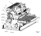
- the fixing unit F shown in Fig. 1 is in one of the copier on one not shown slide known type laterally pulled out position and in a closed position, with radially pressed pressure roller 1 or first lower Roller and fixing roller 2 and the second upper roller shown.
- the fixing unit F has the first roller, the pressure roller 1 in the lower chassis part and as the second roller, the fixing roller 2 in the upper chassis part in a roller pair arrangement for passing and conveying a sheet or ribbon Recording medium S, which in a closed position of the fuser adjacent, axially parallel arrangement with their axial ends in Bearing points L1; L2; L3; L4 of the chassis parts can be operated and rotated.
- the pressure roller 1 is equipped with support means T1; T2, each of which has conventional rotary bearings, in which the pressure roller is freely rotatable about its central axis X1. Furthermore, the pressing roller 1 is equipped with a heating lamp H mounted centrally in it for the purpose of heating it.
- the pressure roller 1 has, as shown in FIGS. 1 to 4, at its two axial ends each have a handle T1; T2 arranged eccentrically to the center axis X1 of the roller Carrying means on such that the roller when removing manually and inserting in vertically radial input / output openings of bearing points L1; L2 of device F, due to their gravity weight, hanging vertically below the handles.
- the handles T1; T2 are by means of annular means 10; 11 on the rigidly arranged concentrically on both shaft ends 12 of the pressure roller 1 fixed annular pivot bearings 13, such as conventional ball or roller bearings, which are pressed onto the outer circumference on both shaft ends, the means 10; 11 are arranged axially spaced from the pressure roller.
- the fastening means 10; 11 of the handles T1; T2 have means 10 on the one hand Axial and radial centering, guiding and holding the pressure roller 1 in their device storage locations L1; L2 open; and on the other hand have means 11 for storing the from the Bearing points L1; L2 of the device or fusing unit F removed from the pressure roller 1 a usual storage pad, not shown.
- the means 10 for centering, guiding and holding the pressure roller 1 are as in FIG. 3 and 4, shown as being substantially concentric around the shaft ends 12 of the roller arranged annular discs 10 formed, the outer diameter of which is larger than that Pressure roller 1 is.
- the means 11 for depositing the pressure roller 1 are in the form of a flat flattening 11 Outer periphery of the ring disk 10 of the means 10 on one of the carrying handles T1; T2 configured opposite lower side, the flat 11 with its flat Contact surface by a predetermined dimension D over the outside diameter of the roller protrudes, so that when the pressure roller 1 is placed on the support surface, e.g. Table top, the pressure roller 1 with its outer circumference does not touch the storage surface and cannot roll away due to the flattening 11.
- Each washer 10 of the two fastening means 10; 11 has essentially two Ring halves 10.1; 10.2 with right-angled ends E for connecting of the ring halves, in such a way that the handles T1; T2 when inserting the pressure roller 1 from above into the bearing points L1; L2 of the device F too radially from the outer circumference Center axis Y1 of the bearing points, running essentially from top to bottom slot-shaped input / output openings of the bearing points L1; L2 of the fixing unit F can be aligned and fixed.
- the two fastening means 10; 11 of the handles T1; T2 by means of an inner circumferential area of their ring disks 10 or ring halves 10.1; 10.2 in a circumferential groove 15 on the outer circumference of the associated annular rotary bearing 13 held radially and axially centered and by means of at the angled ends of the Ring halves screwed screws 14 rigidly fixed to the pivot bearings 13.
- the two are Fastening means 10; 11 of the handles T1; T2 by means of an outer peripheral region of their Ring disks 10 or the lower ring halves 10.2 in one on the inner circumference of the assigned semicircular bearing points L1, L2, in particular on the inner circumference of essential semicircular or U-shaped bearing bracket 20 of the bearings circumferential groove 21 held radially and axially centered, the ends E of the lower, ring halves 10.2 comprising approximately 200 degrees of circumferential angle on the axially to the groove 21 in Stops 22 offset in the direction of the roller rest.
- the handles T1, T2 of the pressure roller 1 are, as shown in FIGS. 1 to 4, radial to Center axis X1 of the pressure roller offset at the upper region of the upper ring halves 10.1 by means of connecting means 17, e.g. two screws rigidly attached.
- the handles in Shape of substantially cylindrical knobs are also improved for further Handling the pressure roller 1 during a replacement by a Operator and to create a free area above the roller arranged that they in the axial direction via their bearing points L1; L2 of the device or the Protruding unit F protrude outwards.
- T2 from heat radiation from the heating lamp are on two axial ends of the pressure roller 1, externally connected to the upper Ring halves 10.1 of the handle fastening means 10 each have a lamp holder 16 in the form a Z-shaped sheet metal bracket.
- the lamp holder 16 here Holding or clamping the axial ends of the heating lamp circular openings with V-shaped, resilient insertion slots.
Landscapes
- Physics & Mathematics (AREA)
- General Physics & Mathematics (AREA)
- Fixing For Electrophotography (AREA)
- Rolls And Other Rotary Bodies (AREA)
- Spinning Or Twisting Of Yarns (AREA)
- Color Electrophotography (AREA)
- Replacement Of Web Rolls (AREA)
Abstract
Description
- Fig. 1
- die erfindungsgemäße an einer Anpresswalze einer aus einem Vervielfältigungsgerät herausgezogenen und geschlossenen Fixiereinheit in einer räumlichen Darstellung,
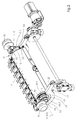
- Fig. 2
- die erfindungsgemäße Vorrichtung nach Fig. 1 an einer aus der Fixiereinheit herausgelösten Anpresswalze in einer vergrößerten räumlichen Darstellung,
- Fig. 3
- die erfindungsgemäße Vorrichtung nach Fig. 2 als vergrößerte Teildarstellung in einer Frontansicht,
- Fig. 4
- die erfindungsgemäße Vorrichtung nach Fig. 3 in einer Seitenansicht.
Des weiteren ist die Anpresswalze 1 zwecks ihrer Erwärmung mit einer zentrisch in ihr angebrachten Heizlampe H ausgestattet.
- L1
- erste Lagerstelle/n für 1.Walze (Anpresswalze) in Fixiereinheit
- L2
- zweite Lagerstelle/n für 1.Walze (Anpresswalze) in Fixiereinheit
- L3
- erste Lagerstelle/n für 2.Walze (Fixier-/Heizwalze) in Fixiereinheit
- L4
- zweite Lagerstelle/n für 2.Walze (Fixier-/Heizwalze) in Fixiereinheit
- D
- Abstand zwischen Außenumfang der 1. Walze und Auflagefläche der unteren Ringhälfte der Befestigungsmittel /Ringscheiben für Tragegriff
- E
- abgewinkelte Enden an Ringhälften der Befestigungsmittel der Tragegriffe
- F
- Fixiereinheit
- H
- Heizlampe der 1. Walze (Anpresswalze)
- S
- Aufzeichnungsmedium /Blatt oder Band (Papier, Folie etc.)
- T1
- erster Tragegriff/e von Tragemittel der 1.Walze
- T2
- zweiter Tragegriff/e von Tragemittel der 1.Walze
- X1
- Mittenachse der 1.Walze
- X2
- Mittenachse der 2.Walze
- Y 1
- Mittenachse von Lagerstelle für 1.Walze
- Y2
- Mittenachse von Lagerstelle für 2.Walze
- Z
- Schwenkachse der oberen und unteren Chassisteile der Fixiereinheit
- 1
- erste/ untere Walze (Anpresswalze) der Fixiereinheit
- 2
- zweite/ obere Walze(Fixier-/Heizwalze) der Fixiereinheit
- 3
- Mittel zum radialen Trennen (Aneinanderpressen) der Walzen in der Fixiereinheit
- 10
- Befestigungs-Mittel /Ringscheibe für Tragegriff/e an der 1.Walze und Mittel zum axialen/radialen Zentrieren, Führen und Halten der 1.Walze in Lagerstellen der Fixiereinheit
- 10.1
- erste/obere Ringhälfte des Befestigungsmittels
- 10.2
- zweite/untere Ringhälfte des Befestigungsmittels
- 11
- Mittel zum Ablegen der 1.Walze (radiale Abflachung an zweiter unterer Ringhälfte des Befestigungsmittels / der Ringscheibe)
- 12
- Schaftende der 1. Walze
- 13
- Drehlager auf Schaftende der 1.Walze
- 14
- Verbindungselement (Schraube) für Ringhälfte
- 15
- Nut am Außenumfang des Drehlagers für Befestigungsmittel (Ringhälften)
- 16
- Lampenhalter an Befestigungsmittel für Tragegriff
- 17
- Verbindungselement (Schraube) für Tragegriff an Befestigungsmittel
- 20
- Lagerbügel für 1. Walze (Anpresswalze)
- 21
- Nut am Innenumfang des Lagerbügels für Befestigungsmittel (untere Ringhälfte)
- 22
- Anschlag/Auflage für abgewinkelte Enden der Ringhälften am Lagerbügel
- 30
- Betätigungshebel der Trennmittel/Schwenkmittel für die Walzen
Claims (9)
- Vorrichtung zum manuellen Austauschen einer Walze (1) eines Vervielfältigungsgerätes, wobei die Walze mit Tragemitteln ausgestattet ist, in denen sie frei um ihre Mittenachse (X1) drehbar angeordnet ist; und wobei das Gerät (F) einerseits Walzen (1;2) in einer Walzenpaar-Anordnung zum Hindurchführen und Fördern eines blatt- oder bandförmigen Aufzeichnungsmediums (S) aufweist, die in einer aneinander anliegenden, achsenparallelen Anordnung in Lagerstellen (L1;L2;L3;L4) des Gerätes rotierend betreibbar, mit ihren axialen Enden gelagert sind, und andererseits manuell betätigbare Mittel zum Freigeben/Fixieren der Walzen in ihren Lagerstellen sowie zum Trennen/Anpressen (3) der Walzen in radialer Richtung zwecks Entnahme aus und Einsetzen in ihre Lagerstellen angeordnet sind,
dadurch gekennzeichnet, dass die Walze (1) an ihren beiden axialen Enden jeweils einen exzentrisch zur Mittenachse (X1) der Walze angeordneten Tragegriff (T1;T2) als Tragemittel aufweist, derart, dass die Walze beim manuellen Entnehmen aus und Einsetzen in vertikal radial verlaufende Ein/Ausgabe-Öffnungen der Lagerstellen (L1;L2) des Gerätes, bedingt durch ihr Schwerkraftgewicht, unterhalb der Tragegriffe vertikal nach unten hängt. - Vorrichtung nach Anspruch 1,
dadurch gekennzeichnet, dass die Tragegriffe (T1;T2) mittels ringförmiger Mittel (10;11) an starr an Schaftenden (12) der Walze (1) konzentrisch angeordneten ringförmigen Drehlagern (13) befestigt sind. - Vorrichtung nach Anspruch 2,
dadurch gekennzeichnet, dass die Befestigungsmittel (10;11) der Tragegriffe (T1;T2) Mittel (10) zum axialen und radialen Zentrieren, Führen und Halten der Walze (1) in ihren Geräte-Lagerstellen (L1;L2) aufweisen; und dass die Befestigungsmittel (10;11) der Tragegriffe (T1;T2) Mittel (11) zum Ablegen der aus den Lagerstellen (L1;L2) des Gerätes entnommenen Walze (1) auf einer Ablageunterlage aufweisen. - Vorrichtung nach Anspruch 2 oder 3,
dadurch gekennzeichnet, dass die Mittel (10) zum Zentrieren, Führen und Halten der Walze (1) im wesentlichen als konzentrisch um die Schaftenden (12) der Walze angeordnete Ringscheiben (10) ausgebildet sind, deren Außendurchmesser größer als der der Walze (1) ist; und dass die Mittel (11) zum Ablegen der Walze (1) als ebene Abflachung (11) am Außenumfang der Ringscheibe des Mittels (10) an einer den Tragegriffen (T1;T2) gegenüber liegenden unteren Seite ausgestaltet sind, wobei die Abflachung mit ihrer Auflagefläche um ein vorbestimmtes Maß (D) über den Außendurchmesser der Walze hinaus ragt. - Vorrichtung nach Anspruch 4,
dadurch gekennzeichnet, dass jede Ringscheibe (10) der Befestigungsmittel (10;11) im wesentlichen zwei Ringhälften (10.1;10.2) mit rechtwinklig abgewinkelte Enden (E) zum miteinander Verbinden der Ringhälften aufweist, derart, dass die Tragegriffe (T1;T2) beim Einsetzen der Walze (1) in die Lagerstellen (L 1;L2) des Geräts (F) zu radial vom Außenumfang zur Mittenachse (Y1) der Lagerstellen von oben nach unten verlaufenden, im wesentlichen schlitzförmigen Ein/Ausgabe-Öffnungen der Lagerstellen ausrichtbar und fixierbar sind. - Vorrichtung nach Anspruch 2 oder 5,
dadurch gekennzeichnet, dass die Befestigungsmittel (10;11) der Tragegriffe (T1;T2) mittels einem Innenumfangsbereich ihrer Ringscheiben (10) in einer am Außenumfang der zugeordneten ringförmigen Drehlager (13) umlaufenden Nut (15) radial und axial zentriert festhaltbar, und mittels Verbindungselemente (14) untereinander verbindbar und auf den Drehlagern fixierbar sind. - Vorrichtung nach Anspruch 3 oder 5,
dadurch gekennzeichnet, dass die Befestigungsmittel (10;11) der Tragegriffe (T1;T2) mittels einem Außenumfangsbereich ihrer Ringscheiben (10) in einer am Innenumfang der zugeordneten halbkreisförmigen Lagerstellen (L1;L2) umlaufenden Nut (21) radial und axial zentriert festhaltbar sind. - Vorrichtung nach den Ansprüchen 1 bis 7,
dadurch gekennzeichnet, dass die Tragegriffe (T1;T2) der Walze (1) in axialer Richtung über deren Lagerstellen (L1;L2) im Gerät (F) hinausragen; und dass die Tragegriffe (T1;T2) in Form von im wesentlichen zylindrischen Knäufen ausgebildet sind. - Vorrichtung nach den Ansprüchen 1 bis 8,
dadurch gekennzeichnet, dass die Walzen (1;2) in Form von Fixier-, Heiz-, Anpress-, Bild-Transfer- oder Blatt-Förderwalzen ausgebildet sind; und die Walzen in Fixier- (F), Bildtransfer- oder Fördereinheiten des in Form eines Kopierers oder Druckers ausgeführten Vervielfältigungsgerätes angeordnet sind.
Applications Claiming Priority (2)
| Application Number | Priority Date | Filing Date | Title |
|---|---|---|---|
| DE10023614A DE10023614A1 (de) | 2000-05-15 | 2000-05-15 | Vorrichtung zum manuellen Austauschen einer Walze eines Vervielfältigungsgerätes |
| DE10023614 | 2000-05-15 |
Publications (3)
| Publication Number | Publication Date |
|---|---|
| EP1156396A2 true EP1156396A2 (de) | 2001-11-21 |
| EP1156396A3 EP1156396A3 (de) | 2005-01-26 |
| EP1156396B1 EP1156396B1 (de) | 2007-12-05 |
Family
ID=7642015
Family Applications (1)
| Application Number | Title | Priority Date | Filing Date |
|---|---|---|---|
| EP01109441A Expired - Lifetime EP1156396B1 (de) | 2000-05-15 | 2001-04-24 | Vorrichtung zum manuellen Austauschen einer Walze eines Viervielfältigungsgerätes |
Country Status (4)
| Country | Link |
|---|---|
| US (1) | US6549739B2 (de) |
| EP (1) | EP1156396B1 (de) |
| AT (1) | ATE380360T1 (de) |
| DE (2) | DE10023614A1 (de) |
Families Citing this family (5)
| Publication number | Priority date | Publication date | Assignee | Title |
|---|---|---|---|---|
| US7373561B2 (en) * | 2002-10-29 | 2008-05-13 | Broadcom Corporation | Integrated packet bit error rate tester for 10G SERDES |
| US7299760B2 (en) * | 2004-03-05 | 2007-11-27 | Sofec, Inc. | Floating LNG import terminal and method for docking |
| US8655249B2 (en) * | 2011-01-20 | 2014-02-18 | Xerox Corporation | Apparatus, systems, and methods for belt-roll fuser latching |
| KR20150071537A (ko) | 2013-12-18 | 2015-06-26 | 삼성전자주식회사 | 스캐너 장치 및 이를 채용한 화상형성장치 |
| US11945655B1 (en) | 2023-11-06 | 2024-04-02 | Steel Craft Mfg. Inc. | System, apparatus, and method for removing and replacing conveyor system components |
Family Cites Families (9)
| Publication number | Priority date | Publication date | Assignee | Title |
|---|---|---|---|---|
| US4114998A (en) * | 1977-01-14 | 1978-09-19 | Tokyo Shibaura Electric Co., Ltd. | Copying machine with removable photosensitive drum |
| JP2926655B2 (ja) * | 1989-05-19 | 1999-07-28 | 株式会社リコー | 電子写真装置 |
| EP0505404B1 (de) * | 1989-12-13 | 1994-06-01 | Siemens Nixdorf Informationssysteme Aktiengesellschaft | Fixierstation für eine elektrofotografische druck- oder kopiereinrichtung |
| JPH0478888A (ja) * | 1990-07-20 | 1992-03-12 | Ricoh Co Ltd | 電子写真装置の感光体取付構造 |
| US5321479A (en) * | 1992-03-24 | 1994-06-14 | Asahi Kogaku Kogyo Kabushiki Kaisha | Electrophotographic apparatus |
| JPH0627845A (ja) * | 1992-07-13 | 1994-02-04 | Mita Ind Co Ltd | 画像形成装置 |
| JP2901115B2 (ja) * | 1992-11-13 | 1999-06-07 | 三田工業株式会社 | 定着装置 |
| DE4443764B4 (de) * | 1993-12-08 | 2004-09-30 | Ricoh Co., Ltd. | Anordnung zum Halten eines Bildträgers |
| JPH09221246A (ja) * | 1995-12-12 | 1997-08-26 | Ricoh Co Ltd | 回転軸支持装置 |
-
2000
- 2000-05-15 DE DE10023614A patent/DE10023614A1/de not_active Withdrawn
-
2001
- 2001-04-24 AT AT01109441T patent/ATE380360T1/de not_active IP Right Cessation
- 2001-04-24 DE DE50113338T patent/DE50113338D1/de not_active Expired - Lifetime
- 2001-04-24 EP EP01109441A patent/EP1156396B1/de not_active Expired - Lifetime
- 2001-05-07 US US09/850,461 patent/US6549739B2/en not_active Expired - Fee Related
Also Published As
| Publication number | Publication date |
|---|---|
| DE50113338D1 (de) | 2008-01-17 |
| EP1156396B1 (de) | 2007-12-05 |
| US6549739B2 (en) | 2003-04-15 |
| US20020009307A1 (en) | 2002-01-24 |
| ATE380360T1 (de) | 2007-12-15 |
| DE10023614A1 (de) | 2001-11-22 |
| EP1156396A3 (de) | 2005-01-26 |
Similar Documents
| Publication | Publication Date | Title |
|---|---|---|
| DE2064559C3 (de) | Vorrichtung zum Reinigen der Oberfläche einer zum Schmelzfixieren von Tonerbildern benutzten Schmelzfixierwalze | |
| DE3309826C2 (de) | Fixiereinrichtung für ein Kopiergerät | |
| DE3439132C2 (de) | ||
| DE3624060C2 (de) | ||
| DE2409209C3 (de) | Vorrichtung zum Abstreifen eines Kopiebogens von einer Walze eines Kopiergerätes | |
| DE3535765A1 (de) | Vorrichtung zur handhabung von harten disketten fuer die datenspeicherung | |
| DE2522777A1 (de) | Entwicklungsvorrichtung zum entwickeln von abbildungen auf einer sich bewegenden abbildungsoberflaeche | |
| EP1156396B1 (de) | Vorrichtung zum manuellen Austauschen einer Walze eines Viervielfältigungsgerätes | |
| DE4300939A1 (en) | Paper transport system for image prodn. unit esp. copier - has three rollers and three surface parts for closing three guide plates to make pressure contact so that paper can be transported and plates opened for paper release | |
| DE2817300C2 (de) | Elektrofotografisches Kopiergerät mit einer austauschbaren endlichen Fotoleiterbahn | |
| DE68915774T2 (de) | Dynamisch stabile blattklemmvorrichtung für hochgeschwindigkeitsblatt-handhabungstrommeln. | |
| CH669682A5 (de) | ||
| DE69603724T2 (de) | Vorrichtung zur oberflächenbehandlung | |
| DE2653519B1 (de) | Reinigungseinrichtung fuer die Fixierwalze eines Druckfixierwalzenpaares in einem elektrostatischen Kopiergeraet | |
| EP1156397B1 (de) | Vorrichtung zum manuellen Austauschen und Transportieren einer Heizwalze eines Vervielfältigungsgerätes bzw. eines elektrophotographischen Druckers | |
| DE3153658C2 (de) | Bildaufzeichnungsger{t | |
| DE69608149T2 (de) | Bilderzeugungsgerät mit einer Aufnahme für eine Rolle Bildempfangsmaterials | |
| DE4443764B4 (de) | Anordnung zum Halten eines Bildträgers | |
| DE4315513A1 (de) | Einrichtung zur Formatanpassung einer Bogenübergabetrommel | |
| DE10301809A1 (de) | Vorrichtung zum Ein- und Ausbauen einer Walze für einen elektrostatografischen Drucker/Kopierer | |
| DE68903035T2 (de) | Trommel zum klemmen blattfoermiger unterlagen und farbstrahldrucker damit versehen. | |
| DE2263468A1 (de) | Vorrichtung zur vereinzelung blattfoermiger aufzeichnungstraeger | |
| EP1155836B1 (de) | Vorrichtung zum Zuführen einer Druckplatte zu einem Plattenzylinder einer Druckmaschine | |
| DE4038307C2 (de) | Einrichtung zum Transportieren von Aufzeichnungsblättern in einer Bilderzeugungseinrichtung zum Herstellen einer beidseitigen Kopie | |
| DE69803959T2 (de) | Führungsmechanismus für Papierrolle und Führungsgerät für Papiermagazin |
Legal Events
| Date | Code | Title | Description |
|---|---|---|---|
| PUAI | Public reference made under article 153(3) epc to a published international application that has entered the european phase |
Free format text: ORIGINAL CODE: 0009012 |
|
| AK | Designated contracting states |
Kind code of ref document: A2 Designated state(s): AT BE CH CY DE DK ES FI FR GB GR IE IT LI LU MC NL PT SE TR |
|
| AX | Request for extension of the european patent |
Free format text: AL;LT;LV;MK;RO;SI |
|
| RAP1 | Party data changed (applicant data changed or rights of an application transferred) |
Owner name: EASTMAN KODAK COMPANY |
|
| PUAL | Search report despatched |
Free format text: ORIGINAL CODE: 0009013 |
|
| AK | Designated contracting states |
Kind code of ref document: A3 Designated state(s): AT BE CH CY DE DK ES FI FR GB GR IE IT LI LU MC NL PT SE TR |
|
| AX | Request for extension of the european patent |
Extension state: AL LT LV MK RO SI |
|
| 17P | Request for examination filed |
Effective date: 20050604 |
|
| AKX | Designation fees paid |
Designated state(s): AT BE CH CY DE DK ES FI FR GB GR IE IT LI LU MC NL PT SE TR |
|
| 17Q | First examination report despatched |
Effective date: 20060614 |
|
| GRAP | Despatch of communication of intention to grant a patent |
Free format text: ORIGINAL CODE: EPIDOSNIGR1 |
|
| GRAS | Grant fee paid |
Free format text: ORIGINAL CODE: EPIDOSNIGR3 |
|
| GRAA | (expected) grant |
Free format text: ORIGINAL CODE: 0009210 |
|
| AK | Designated contracting states |
Kind code of ref document: B1 Designated state(s): AT BE CH CY DE DK ES FI FR GB GR IE IT LI LU MC NL PT SE TR |
|
| REG | Reference to a national code |
Ref country code: GB Ref legal event code: FG4D Free format text: NOT ENGLISH |
|
| REG | Reference to a national code |
Ref country code: IE Ref legal event code: FG4D Free format text: LANGUAGE OF EP DOCUMENT: GERMAN |
|
| REG | Reference to a national code |
Ref country code: CH Ref legal event code: EP |
|
| REF | Corresponds to: |
Ref document number: 50113338 Country of ref document: DE Date of ref document: 20080117 Kind code of ref document: P |
|
| PG25 | Lapsed in a contracting state [announced via postgrant information from national office to epo] |
Ref country code: ES Free format text: LAPSE BECAUSE OF FAILURE TO SUBMIT A TRANSLATION OF THE DESCRIPTION OR TO PAY THE FEE WITHIN THE PRESCRIBED TIME-LIMIT Effective date: 20080316 Ref country code: SE Free format text: LAPSE BECAUSE OF FAILURE TO SUBMIT A TRANSLATION OF THE DESCRIPTION OR TO PAY THE FEE WITHIN THE PRESCRIBED TIME-LIMIT Effective date: 20080305 Ref country code: NL Free format text: LAPSE BECAUSE OF FAILURE TO SUBMIT A TRANSLATION OF THE DESCRIPTION OR TO PAY THE FEE WITHIN THE PRESCRIBED TIME-LIMIT Effective date: 20071205 |
|
| PG25 | Lapsed in a contracting state [announced via postgrant information from national office to epo] |
Ref country code: FI Free format text: LAPSE BECAUSE OF FAILURE TO SUBMIT A TRANSLATION OF THE DESCRIPTION OR TO PAY THE FEE WITHIN THE PRESCRIBED TIME-LIMIT Effective date: 20071205 |
|
| NLV1 | Nl: lapsed or annulled due to failure to fulfill the requirements of art. 29p and 29m of the patents act | ||
| GBV | Gb: ep patent (uk) treated as always having been void in accordance with gb section 77(7)/1977 [no translation filed] | ||
| PG25 | Lapsed in a contracting state [announced via postgrant information from national office to epo] |
Ref country code: PT Free format text: LAPSE BECAUSE OF FAILURE TO SUBMIT A TRANSLATION OF THE DESCRIPTION OR TO PAY THE FEE WITHIN THE PRESCRIBED TIME-LIMIT Effective date: 20080505 |
|
| REG | Reference to a national code |
Ref country code: IE Ref legal event code: FD4D |
|
| EN | Fr: translation not filed | ||
| PLBE | No opposition filed within time limit |
Free format text: ORIGINAL CODE: 0009261 |
|
| STAA | Information on the status of an ep patent application or granted ep patent |
Free format text: STATUS: NO OPPOSITION FILED WITHIN TIME LIMIT |
|
| BERE | Be: lapsed |
Owner name: EASTMAN KODAK CY Effective date: 20080430 |
|
| PG25 | Lapsed in a contracting state [announced via postgrant information from national office to epo] |
Ref country code: DK Free format text: LAPSE BECAUSE OF FAILURE TO SUBMIT A TRANSLATION OF THE DESCRIPTION OR TO PAY THE FEE WITHIN THE PRESCRIBED TIME-LIMIT Effective date: 20071205 Ref country code: IE Free format text: LAPSE BECAUSE OF FAILURE TO SUBMIT A TRANSLATION OF THE DESCRIPTION OR TO PAY THE FEE WITHIN THE PRESCRIBED TIME-LIMIT Effective date: 20071205 |
|
| 26N | No opposition filed |
Effective date: 20080908 |
|
| PG25 | Lapsed in a contracting state [announced via postgrant information from national office to epo] |
Ref country code: MC Free format text: LAPSE BECAUSE OF NON-PAYMENT OF DUE FEES Effective date: 20080430 Ref country code: GB Free format text: LAPSE BECAUSE OF FAILURE TO SUBMIT A TRANSLATION OF THE DESCRIPTION OR TO PAY THE FEE WITHIN THE PRESCRIBED TIME-LIMIT Effective date: 20071205 |
|
| REG | Reference to a national code |
Ref country code: CH Ref legal event code: PL |
|
| PG25 | Lapsed in a contracting state [announced via postgrant information from national office to epo] |
Ref country code: CH Free format text: LAPSE BECAUSE OF NON-PAYMENT OF DUE FEES Effective date: 20080430 Ref country code: GR Free format text: LAPSE BECAUSE OF FAILURE TO SUBMIT A TRANSLATION OF THE DESCRIPTION OR TO PAY THE FEE WITHIN THE PRESCRIBED TIME-LIMIT Effective date: 20080306 Ref country code: LI Free format text: LAPSE BECAUSE OF NON-PAYMENT OF DUE FEES Effective date: 20080430 |
|
| PG25 | Lapsed in a contracting state [announced via postgrant information from national office to epo] |
Ref country code: BE Free format text: LAPSE BECAUSE OF NON-PAYMENT OF DUE FEES Effective date: 20080430 |
|
| PG25 | Lapsed in a contracting state [announced via postgrant information from national office to epo] |
Ref country code: FR Free format text: LAPSE BECAUSE OF FAILURE TO SUBMIT A TRANSLATION OF THE DESCRIPTION OR TO PAY THE FEE WITHIN THE PRESCRIBED TIME-LIMIT Effective date: 20081003 |
|
| PG25 | Lapsed in a contracting state [announced via postgrant information from national office to epo] |
Ref country code: CY Free format text: LAPSE BECAUSE OF FAILURE TO SUBMIT A TRANSLATION OF THE DESCRIPTION OR TO PAY THE FEE WITHIN THE PRESCRIBED TIME-LIMIT Effective date: 20071205 |
|
| PG25 | Lapsed in a contracting state [announced via postgrant information from national office to epo] |
Ref country code: AT Free format text: LAPSE BECAUSE OF NON-PAYMENT OF DUE FEES Effective date: 20080424 |
|
| PG25 | Lapsed in a contracting state [announced via postgrant information from national office to epo] |
Ref country code: LU Free format text: LAPSE BECAUSE OF NON-PAYMENT OF DUE FEES Effective date: 20080424 |
|
| PG25 | Lapsed in a contracting state [announced via postgrant information from national office to epo] |
Ref country code: TR Free format text: LAPSE BECAUSE OF FAILURE TO SUBMIT A TRANSLATION OF THE DESCRIPTION OR TO PAY THE FEE WITHIN THE PRESCRIBED TIME-LIMIT Effective date: 20071205 |
|
| PG25 | Lapsed in a contracting state [announced via postgrant information from national office to epo] |
Ref country code: IT Free format text: LAPSE BECAUSE OF NON-PAYMENT OF DUE FEES Effective date: 20080430 |
|
| PGFP | Annual fee paid to national office [announced via postgrant information from national office to epo] |
Ref country code: DE Payment date: 20130430 Year of fee payment: 13 |
|
| REG | Reference to a national code |
Ref country code: DE Ref legal event code: R119 Ref document number: 50113338 Country of ref document: DE |
|
| REG | Reference to a national code |
Ref country code: DE Ref legal event code: R119 Ref document number: 50113338 Country of ref document: DE Effective date: 20141101 |
|
| PG25 | Lapsed in a contracting state [announced via postgrant information from national office to epo] |
Ref country code: DE Free format text: LAPSE BECAUSE OF NON-PAYMENT OF DUE FEES Effective date: 20141101 |