EP1155827A1 - Antrieb eines Anlegers für eine Bogen verarbeitende Maschine - Google Patents
Antrieb eines Anlegers für eine Bogen verarbeitende Maschine Download PDFInfo
- Publication number
- EP1155827A1 EP1155827A1 EP01110015A EP01110015A EP1155827A1 EP 1155827 A1 EP1155827 A1 EP 1155827A1 EP 01110015 A EP01110015 A EP 01110015A EP 01110015 A EP01110015 A EP 01110015A EP 1155827 A1 EP1155827 A1 EP 1155827A1
- Authority
- EP
- European Patent Office
- Prior art keywords
- drive shaft
- drive
- distance
- gear
- axis
- Prior art date
- Legal status (The legal status is an assumption and is not a legal conclusion. Google has not performed a legal analysis and makes no representation as to the accuracy of the status listed.)
- Granted
Links
Images

Classifications
-
- F—MECHANICAL ENGINEERING; LIGHTING; HEATING; WEAPONS; BLASTING
- F16—ENGINEERING ELEMENTS AND UNITS; GENERAL MEASURES FOR PRODUCING AND MAINTAINING EFFECTIVE FUNCTIONING OF MACHINES OR INSTALLATIONS; THERMAL INSULATION IN GENERAL
- F16H—GEARING
- F16H35/00—Gearings or mechanisms with other special functional features
- F16H35/02—Gearings or mechanisms with other special functional features for conveying rotary motion with cyclically varying velocity ratio
-
- B—PERFORMING OPERATIONS; TRANSPORTING
- B65—CONVEYING; PACKING; STORING; HANDLING THIN OR FILAMENTARY MATERIAL
- B65H—HANDLING THIN OR FILAMENTARY MATERIAL, e.g. SHEETS, WEBS, CABLES
- B65H5/00—Feeding articles separated from piles; Feeding articles to machines
- B65H5/08—Feeding articles separated from piles; Feeding articles to machines by grippers, e.g. suction grippers
- B65H5/10—Reciprocating or oscillating grippers, e.g. suction or gripper tables
-
- B—PERFORMING OPERATIONS; TRANSPORTING
- B41—PRINTING; LINING MACHINES; TYPEWRITERS; STAMPS
- B41P—INDEXING SCHEME RELATING TO PRINTING, LINING MACHINES, TYPEWRITERS, AND TO STAMPS
- B41P2213/00—Arrangements for actuating or driving printing presses; Auxiliary devices or processes
- B41P2213/40—Auxiliary devices or processes associated with the drives
- B41P2213/42—Vibration-dampers for machine parts
-
- B—PERFORMING OPERATIONS; TRANSPORTING
- B65—CONVEYING; PACKING; STORING; HANDLING THIN OR FILAMENTARY MATERIAL
- B65H—HANDLING THIN OR FILAMENTARY MATERIAL, e.g. SHEETS, WEBS, CABLES
- B65H2403/00—Power transmission; Driving means
- B65H2403/40—Toothed gearings
- B65H2403/48—Other
- B65H2403/483—Differential gearing
-
- F—MECHANICAL ENGINEERING; LIGHTING; HEATING; WEAPONS; BLASTING
- F16—ENGINEERING ELEMENTS AND UNITS; GENERAL MEASURES FOR PRODUCING AND MAINTAINING EFFECTIVE FUNCTIONING OF MACHINES OR INSTALLATIONS; THERMAL INSULATION IN GENERAL
- F16H—GEARING
- F16H35/00—Gearings or mechanisms with other special functional features
- F16H2035/001—Gearings with eccentrically mounted gears, e.g. for cyclically varying ratio
-
- F—MECHANICAL ENGINEERING; LIGHTING; HEATING; WEAPONS; BLASTING
- F16—ENGINEERING ELEMENTS AND UNITS; GENERAL MEASURES FOR PRODUCING AND MAINTAINING EFFECTIVE FUNCTIONING OF MACHINES OR INSTALLATIONS; THERMAL INSULATION IN GENERAL
- F16H—GEARING
- F16H25/00—Gearings comprising primarily only cams, cam-followers and screw-and-nut mechanisms
- F16H25/16—Gearings comprising primarily only cams, cam-followers and screw-and-nut mechanisms for interconverting rotary motion and oscillating motion
-
- F—MECHANICAL ENGINEERING; LIGHTING; HEATING; WEAPONS; BLASTING
- F16—ENGINEERING ELEMENTS AND UNITS; GENERAL MEASURES FOR PRODUCING AND MAINTAINING EFFECTIVE FUNCTIONING OF MACHINES OR INSTALLATIONS; THERMAL INSULATION IN GENERAL
- F16H—GEARING
- F16H33/00—Gearings based on repeated accumulation and delivery of energy
- F16H33/02—Rotary transmissions with mechanical accumulators, e.g. weights, springs, intermittently-connected flywheels
Definitions
- the invention relates to a drive for a feeder for a sheet processing machine, in particular a printing press, with a drive shaft driven at a uniform speed, in particular a single-speed shaft, of which a device via a gear drive of the feeder accelerating during one revolution of the drive shaft and can be driven by delayed movement.
- Such drives are found in investors e.g. to drive the tapes one Belt table with sinusoidal speed curve application.
- the drive roller of the conveyor table as well as the gears of the single-speed shaft leading gear drive due to their Mass inertia when changing from accelerating to decelerating If you want to move ahead, the gears will Change of tooth flanks and vibrations in the gear drive, which leads to leads to increased wear.
- the object of the invention is therefore a drive of the aforementioned Type to create such loads on the components of the drive be significantly reduced.
- a mass balance gear can be driven by which is a swelling in the acceleration phase of the movement of the device Counter moment and an increasing in the deceleration phase Support torque acts on the drive shaft.
- a drive that is simply designed with a few components is achieved that an eccentric drive gear on the stationary drive shaft is arranged, through which another gear of the gear drive can be driven is, which is concentric about an axis of rotation axial to the drive shaft is rotatable, the distance between the drive shaft and the axis of rotation during one revolution of the drive shaft between one Maximum distance and a small bar distance is changeable and while a spring force as the distance increases towards the maximum distance a swelling support moment and while reducing the distance after the maximum distance the spring force swells Counter torque on the drive shaft.
- the radially projecting arm is coaxial on the drive shaft arranged disc.
- Another drive that is also easy to set up with just a few components is achieved in that a cam plate is arranged on the drive shaft whose radial circumferential contour is approximately radial from a spring force is acted upon, the distance between the application point of the Spring force on the contour to the axis of the drive shaft during the start reducing the distance between the drive shaft and the axis of rotation further gear from the largest distance tangentially Approximate drive shaft.
- lever is a two-armed lever
- the roller is arranged and the other Arm is loaded by a spring.
- the spring can preferably be a tension spring, with one End on the pivot lever and with its other end stationary is arranged.
- the device to be driven by the investor can be the driving role Belt table or a suction cup drive.
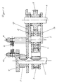
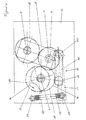
- the drive of an investor shown in the figures has a drive shaft 1, which is a single-tour shaft and with a constant speed via the gear 2 fixedly arranged on the drive shaft 1 by a Rotary drive, not shown, in a counterclockwise direction Direction of rotation 14 is driven.
- a drive gear 3 is arranged eccentrically on the drive shaft 1, through which a third gear 5 can be driven via a further gear 4.
- the increasing and decreasing speed is due to the eccentric Arrangement of the drive gear 3 on the with even Rotational speed driven drive shaft 1 generated and over the Gear drive of the further gear 4 and the third gear 5 on the Wave 6 transmitted.
- first retaining screw 10 On the first retaining screw 10 is a tension spring 11 with one end attached. With its other end, the tension spring 11 is on a second one Fixing screw 12 attached, which in turn is fixed to the frame 13 of the Investor is arranged.
- the arrangement of the second retaining screw 11 on the frame 13 of the feeder is such that the tension spring 11 approximately in the position of the lowest Decency between drive shaft 1 and axis of rotation 7 of the further gear 4 their greatest extent and approximately in the position of the greatest distance between drive shaft 1 and axis of rotation 7 of the further gear 4 has its smallest extent.
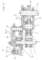
- a cam 15 arranged in a rotationally fixed manner, the radially rotating one Contour 16 is acted upon approximately radially by a roller 17.
- the roll is 17 freely rotatable at one end of a first lever arm 18 of a two-armed Lever 19 arranged around a to the axis of rotation of the drive shaft 1 parallel, fixed pivot axis 20 is pivotable.
- a tension spring 22 with one end by means attached a retaining screw 23, the other end over another Retaining screw 24 is attached to the frame 13 of the feeder.
- the cam disc 15 has about 290 ° with only a small eccentricity approximately the same radial distance between their contour 16 and the drive shaft 1, so that in this area largely no moment from the spring-lever system is exerted on the drive shaft 1.
- the remaining approximately 70 ° of the contour 16 are approximately tangential areas 25 and 26 approaching the drive shaft 1, which are approximately form a "V" at a radial distance from the drive shaft 1.
- the roller 17 comes out the radially outer area of the contour 16 and due to high tension the tension spring 22 high contact force in the area 25, which is the drive shaft 1 approximates, the tension of the tension spring 22 and so that the contact force of the roller 17 on the contour 16 but also the effective Radius between the axis of rotation of the cam disc 15 and the point of application the roll 17 reduced.
- the drive shaft 1 receives a cam 15 in the direction of rotation 14 acting support moment, which works just then if the distance between the drive shaft 1 and the axis of rotation 7 is different The greatest distance starts to decrease, so that it is due to wanting to advance further gear 4 does not lead to a tooth flank change between the teeth of the drive gear 3 and the further gear 4 is coming.
Landscapes
- Engineering & Computer Science (AREA)
- Mechanical Engineering (AREA)
- General Engineering & Computer Science (AREA)
- Sheets, Magazines, And Separation Thereof (AREA)
- Transmission Devices (AREA)
- Gear Transmission (AREA)
- Photographic Processing Devices Using Wet Methods (AREA)
- Supply And Installment Of Electrical Components (AREA)
- Delivering By Means Of Belts And Rollers (AREA)
Abstract
Description
- Figur 1
- ein erstes Ausführungsbeispiel eines Antriebs in der Seitenansicht
- Figur 2
- den Antrieb nach Figur 1 in Querschnittsansicht
- Figur 3
- ein zweites Ausführungsbeispiel eines Antriebs in der Seitenansicht
- Figur 4
- den Antrieb nach Figur 3 in Querschnittsansicht.
- 1
- Antriebswelle
- 2
- Zahnrad
- 3
- Antriebszahnrad
- 4
- weiteres Zahnrad
- 5
- drittes Zahnrad
- 6
- Welle
- 7
- Drehachse
- 8
- Schwenkarme
- 9
- Scheibe
- 10
- erste Halteschraube
- 11
- Zugfeder
- 12
- zweite Halteschraube
- 13
- Gestell
- 14
- Drehrichtung
- 15
- Kurvenscheibe
- 16
- Kontur
- 17
- Rolle
- 18
- erster Hebelarm
- 19
- zweiarmiger Hebel
- 20
- Schwenkachse
- 21
- zweiter Hebelarm
- 22
- Zugfeder
- 23
- Halteschraube
- 24
- Halteschraube
- 25
- Bereich
- 26
- Bereich
Claims (10)
- Antrieb eines Anlegers für eine Bogen verarbeitende Maschine, insbesondere eine Druckmaschine, mit einer mit gleichmäßiger Drehzahl angetriebenen Antriebswelle, insbesondere einer Eintourenwelle, von der über einen Zahnradtrieb eine Einrichtung des Anlegers während einer Umdrehung der Antriebswelle mit sich beschleunigender und sich verzögernder Bewegung antreibbar ist, dadurch gekennzeichnet, daß von der Antriebswelle (1) zusätzlich ein Momentenausgleichsgetriebe antreibbar ist, durch das in der Beschleunigungsphase der Bewegung der Einrichtung ein anschwellendes Gegenmoment und in der Verzögerungsphase ein anschwellendes Unterstützungsmoment auf die Antriebswelle (1) wirkt.
- Antrieb nach Anspruch 1,dadurch gekennzeichnet, daß auf der ortsfesten Antriebswelle (1) exzentrisch ein Antriebszahnrad (3) angeordnet ist, durch das ein weiteres Zahnrad (4) des Zahnradtriebs antreibbar ist, welches konzentrisch um eine zur Antriebswelle (1) axiale Drehachse (7) drehbar ist, wobei der Abstand zwischen Antriebswelle (1) und Drehachse (7) während einer Umdrehung derAntriebswelle (1) zwischen einem Größtabstand und einem Kleinstabstand änderbar ist und wobei während des Anwachsens des Abstandes zum Größtabstand hin eine Federkraft ein anschwellendes Unterstützungsmoment und während des Reduzierens des Abstandes nach dem Größtabstand die Federkraft ein anschwellendes Gegenmoment auf die Antriebswelle (1) ausübt.
- Antrieb nach Anspruch 2, dadurch gekennzeichnet, daß auf der Antriebswelle (1) ein radial wegragender Arm fest angeordnet ist, an dem in einem Abstand zur Achse der Antriebswelle (1) eine Zugfeder (11) mit ihrem einen Ende angreift, die mit ihrem anderen Ende ortsfest in einem radialen Abstand zur Antriebswelle (1) befestigt ist, wobei die Zugfeder (11) etwa in der Position des geringsten Abstands zwischen Antriebswelle (1) und Drehachse (7) des weiteren Zahnrads (4) ihre größte Ausdehnung aufweist.
- Antrieb nach Anspruch 3, dadurch gekennzeichnet, daß der radial wegragende Arm eine koaxial auf der Antriebswelle (1) angeordnete Scheibe (9) ist.
- Antrieb nach Anspruch 2, dadurch gekennzeichnet, daß auf der Antriebswelle (1) eine Kurvenscheibe (15) angeordnet ist, deren radial umlaufende Kontur (16) etwa radial von einer Federkraft beaufschlagt ist, wobei der Abstand des Beaufschlagungspunkts der Federkraft auf der Kontur (16) zur Achse der Antriebswelle (1) während des Beginns des Reduzierens des Abstands zwischen Antriebswelle (1) und Drehachse (7) des weiteren Zahnrads (4) vom Größtabstand her sich tangential der Antriebswelle (1) annähert.
- Antrieb nach Anspruch 5, dadurch gekennzeichnet, daß eine frei drehbar an einem Ende eines Schwenkhebels gelagerte Rolle (17) an der radial umlaufenden Kontur (16) der Kurvenscheibe (15) in Anlage ist, wobei der um eine im Abstand zur Rolle (17) um eine Schwenkachse (20) schwenkbare Schwenkhebel von einer vorgespannten Feder (22) mit der Rolle (17) gegen die Kontur (16) der Kurvenscheibe (15) beaufschlagt ist.
- Antrieb nach Anspruch 6, dadurch gekennzeichnet, daß der Hebel ein zweiarmiger Hebel i(19) ist, an dessen einem Hebelarm (18) die Rolle (17) angeordnet ist und dessen anderer Hebelarm (19) von einer Feder (22) beaufschlagt ist.
- Antrieb nach Anspruch 7, dadurch gekennzeichnet, daß die Feder eine Zugfeder (22) ist, die mit ihrem einen Ende an dem Schwenkhebel und mit ihrem anderen Ende ortsfest angeordnet ist.
- Antrieb nach einem der vorhergehenden Ansprüche, dadurch gekennzeichnet, daß die Einrichtung des Anlegers die Antriebsrolle eines Bändertischs ist.
- Antrieb nach einem der Ansprüche 1 bis 8, dadurch gekennzeichnet, daß die Einrichtung des Anlegers ein Schleppsaugerantrieb ist.
Applications Claiming Priority (2)
| Application Number | Priority Date | Filing Date | Title |
|---|---|---|---|
| DE10023682A DE10023682A1 (de) | 2000-05-16 | 2000-05-16 | Antrieb eines Anlegers für eine Bogen verarbeitende Maschine |
| DE10023682 | 2000-05-16 |
Publications (2)
| Publication Number | Publication Date |
|---|---|
| EP1155827A1 true EP1155827A1 (de) | 2001-11-21 |
| EP1155827B1 EP1155827B1 (de) | 2003-10-08 |
Family
ID=7642065
Family Applications (1)
| Application Number | Title | Priority Date | Filing Date |
|---|---|---|---|
| EP01110015A Expired - Lifetime EP1155827B1 (de) | 2000-05-16 | 2001-04-26 | Antrieb eines Anlegers für eine Bogen verarbeitende Maschine |
Country Status (3)
| Country | Link |
|---|---|
| EP (1) | EP1155827B1 (de) |
| AT (1) | ATE251547T1 (de) |
| DE (2) | DE10023682A1 (de) |
Cited By (1)
| Publication number | Priority date | Publication date | Assignee | Title |
|---|---|---|---|---|
| CN103032540A (zh) * | 2012-12-31 | 2013-04-10 | 浙江通业印刷机械有限公司 | 输纸传动变速机构 |
Citations (5)
| Publication number | Priority date | Publication date | Assignee | Title |
|---|---|---|---|---|
| DE1910733A1 (de) * | 1969-03-03 | 1970-09-17 | Spiess Dr Ing Helmut | Antrieb fuer Bogenanleger |
| EP0182593A1 (de) * | 1984-11-13 | 1986-05-28 | The Mead Corporation | Kurvengetriebe für eine Vereinzelvorrichtung |
| DD266784A1 (de) * | 1987-11-18 | 1989-04-12 | Polygraph Leipzig | Antrieb fuer ein kurvengesteuertes bogenzufuehrsystem |
| DE4102472A1 (de) * | 1991-01-20 | 1992-08-06 | Heidelberger Druckmasch Ag | Rotationsdruckmaschine zur verarbeitung von bogen |
| DE19835005A1 (de) * | 1997-12-20 | 1999-06-24 | Heidelberger Druckmasch Ag | Kurvengesteuertes Leistungsausgleichsgetriebe für ein Bogenbeschleunigungssystem |
Family Cites Families (3)
| Publication number | Priority date | Publication date | Assignee | Title |
|---|---|---|---|---|
| DE1263434B (de) * | 1966-09-02 | 1968-03-14 | Ibm Deutschland | Kurvengetriebe mit Drehmomentausgleich |
| DE1761306A1 (de) * | 1968-05-02 | 1971-05-13 | Polygraph Leipzig | Bogenanlegergetriebe,welches ueber eine ausrueckbare Kupplung mit der Bogenverarbeitungsmaschine gekoppelt ist und die Bogenvereinzelungsbzw.Bogenfoerdereinrichtungen bei gleichfoermigem Antrieb des Getriebes mit ungleichfoermiger Geschwindigkeit antreibt |
| DE19540573C1 (de) * | 1995-10-31 | 1996-11-07 | Roland Man Druckmasch | Vorrichtung zum Spielausgleich in Rotationsdruckmaschinen |
-
2000
- 2000-05-16 DE DE10023682A patent/DE10023682A1/de not_active Withdrawn
-
2001
- 2001-04-26 AT AT01110015T patent/ATE251547T1/de active
- 2001-04-26 EP EP01110015A patent/EP1155827B1/de not_active Expired - Lifetime
- 2001-04-26 DE DE50100738T patent/DE50100738D1/de not_active Expired - Lifetime
Patent Citations (5)
| Publication number | Priority date | Publication date | Assignee | Title |
|---|---|---|---|---|
| DE1910733A1 (de) * | 1969-03-03 | 1970-09-17 | Spiess Dr Ing Helmut | Antrieb fuer Bogenanleger |
| EP0182593A1 (de) * | 1984-11-13 | 1986-05-28 | The Mead Corporation | Kurvengetriebe für eine Vereinzelvorrichtung |
| DD266784A1 (de) * | 1987-11-18 | 1989-04-12 | Polygraph Leipzig | Antrieb fuer ein kurvengesteuertes bogenzufuehrsystem |
| DE4102472A1 (de) * | 1991-01-20 | 1992-08-06 | Heidelberger Druckmasch Ag | Rotationsdruckmaschine zur verarbeitung von bogen |
| DE19835005A1 (de) * | 1997-12-20 | 1999-06-24 | Heidelberger Druckmasch Ag | Kurvengesteuertes Leistungsausgleichsgetriebe für ein Bogenbeschleunigungssystem |
Cited By (3)
| Publication number | Priority date | Publication date | Assignee | Title |
|---|---|---|---|---|
| CN103032540A (zh) * | 2012-12-31 | 2013-04-10 | 浙江通业印刷机械有限公司 | 输纸传动变速机构 |
| CN103032540B (zh) * | 2012-12-31 | 2016-09-21 | 浙江通业印刷机械有限公司 | 输纸传动变速机构 |
| CN106438902A (zh) * | 2012-12-31 | 2017-02-22 | 浙江通业印刷机械有限公司 | 输纸传动变速机构 |
Also Published As
| Publication number | Publication date |
|---|---|
| ATE251547T1 (de) | 2003-10-15 |
| DE50100738D1 (de) | 2003-11-13 |
| EP1155827B1 (de) | 2003-10-08 |
| DE10023682A1 (de) | 2001-11-22 |
Similar Documents
| Publication | Publication Date | Title |
|---|---|---|
| DE3626185A1 (de) | Getriebe zur bildung einer zyklisch ablaufenden bewegung aus einer rotationsbewegung | |
| DE2325244A1 (de) | Einrichtung zum vereinzeln, transportieren und gegebenenfalls behandeln von in einer station als stapel bevorrateten blattfoermigen zuschnitten, insbesondere etikettiermaschine | |
| EP0135063B1 (de) | Vorgreiferantrieb | |
| DE2102412B2 (de) | Verstellvorrichtung an kurbelwellenschleifmaschinen zum ausrichten der zu schleifenden kurbelzapfen | |
| DE3616029A1 (de) | Vorrichtung zum querperforieren von papierbahnen | |
| DE3726780A1 (de) | Vorrichtung zur uebergabe von bogen | |
| DE19940532B4 (de) | Druckmaschine mit einem Heberfarbwerk | |
| EP1041027A2 (de) | Vorrichtung zum Transportieren von Signaturen in Druckmaschinen | |
| DE3133729C2 (de) | Schwingantriebsvorrichtung | |
| EP1155827B1 (de) | Antrieb eines Anlegers für eine Bogen verarbeitende Maschine | |
| DE2224932C2 (de) | Vorgreifersteuerung für Bogenrotationsdruckmaschinen | |
| EP0719722A2 (de) | Zugwalzenantrieb | |
| EP0107836B1 (de) | Getriebe zur Erzeugung eines ungleichförmigen Abtriebes aus einem gleichförmigen Antrieb | |
| DE4101847C2 (de) | Kurvengetriebe | |
| DE2624170A1 (de) | Seitenausrichtvorrichtung | |
| EP1842606A1 (de) | Vorrichtung zum schleifenförmigen Biegen eines fortlaufenden Drahtes | |
| DE2220343C3 (de) | Vorrichtung zum Antrieb eines schwingenden Vorgreifers einer Druckmaschine | |
| DE483180C (de) | Veraenderlicher Antrieb einer Drehachse mit Hilfe eines ununterbrochen laufenden Antriebsraedervorgeleges | |
| DE2253037B2 (de) | Changiervorrichtung | |
| DE4109824A1 (de) | Kurvengesteuertes leistungsausgleichsgetriebe | |
| DE1436529C3 (de) | ||
| DE2740656C3 (de) | Etikettiermaschine, insbesondere für Flaschen | |
| DE4109409C2 (de) | Kurvengesteuertes Bogenbeschleunigungssystem mit Leistungsausgleich | |
| DE4431682C2 (de) | Kurvengesteuertes Bogenbeschleunigungssystem | |
| DE4431680C2 (de) | Antrieb eines Bogenbeschleunigungssystems |
Legal Events
| Date | Code | Title | Description |
|---|---|---|---|
| PUAI | Public reference made under article 153(3) epc to a published international application that has entered the european phase |
Free format text: ORIGINAL CODE: 0009012 |
|
| 17P | Request for examination filed |
Effective date: 20010918 |
|
| AK | Designated contracting states |
Kind code of ref document: A1 Designated state(s): AT BE CH CY DE DK ES FI FR GB GR IE IT LI LU MC NL PT SE TR Kind code of ref document: A1 Designated state(s): AT CH DE FR GB LI |
|
| AX | Request for extension of the european patent |
Free format text: AL;LT;LV;MK;RO;SI |
|
| AKX | Designation fees paid |
Free format text: AT CH DE FR GB LI |
|
| 17Q | First examination report despatched |
Effective date: 20021022 |
|
| GRAH | Despatch of communication of intention to grant a patent |
Free format text: ORIGINAL CODE: EPIDOS IGRA |
|
| GRAH | Despatch of communication of intention to grant a patent |
Free format text: ORIGINAL CODE: EPIDOS IGRA |
|
| GRAA | (expected) grant |
Free format text: ORIGINAL CODE: 0009210 |
|
| AK | Designated contracting states |
Kind code of ref document: B1 Designated state(s): AT CH DE FR GB LI |
|
| PG25 | Lapsed in a contracting state [announced via postgrant information from national office to epo] |
Ref country code: FR Free format text: LAPSE BECAUSE OF FAILURE TO SUBMIT A TRANSLATION OF THE DESCRIPTION OR TO PAY THE FEE WITHIN THE PRESCRIBED TIME-LIMIT Effective date: 20031008 Ref country code: GB Free format text: LAPSE BECAUSE OF FAILURE TO SUBMIT A TRANSLATION OF THE DESCRIPTION OR TO PAY THE FEE WITHIN THE PRESCRIBED TIME-LIMIT Effective date: 20031008 |
|
| REG | Reference to a national code |
Ref country code: GB Ref legal event code: FG4D Free format text: NOT ENGLISH |
|
| REG | Reference to a national code |
Ref country code: CH Ref legal event code: EP |
|
| REF | Corresponds to: |
Ref document number: 50100738 Country of ref document: DE Date of ref document: 20031113 Kind code of ref document: P |
|
| GBV | Gb: ep patent (uk) treated as always having been void in accordance with gb section 77(7)/1977 [no translation filed] |
Effective date: 20031008 |
|
| PLBE | No opposition filed within time limit |
Free format text: ORIGINAL CODE: 0009261 |
|
| STAA | Information on the status of an ep patent application or granted ep patent |
Free format text: STATUS: NO OPPOSITION FILED WITHIN TIME LIMIT |
|
| 26N | No opposition filed |
Effective date: 20040709 |
|
| EN | Fr: translation not filed | ||
| PG25 | Lapsed in a contracting state [announced via postgrant information from national office to epo] |
Ref country code: CH Free format text: LAPSE BECAUSE OF NON-PAYMENT OF DUE FEES Effective date: 20050430 Ref country code: LI Free format text: LAPSE BECAUSE OF NON-PAYMENT OF DUE FEES Effective date: 20050430 |
|
| REG | Reference to a national code |
Ref country code: CH Ref legal event code: PL |
|
| PGFP | Annual fee paid to national office [announced via postgrant information from national office to epo] |
Ref country code: AT Payment date: 20110414 Year of fee payment: 11 |
|
| REG | Reference to a national code |
Ref country code: DE Ref legal event code: R081 Ref document number: 50100738 Country of ref document: DE Owner name: MANROLAND SHEETFED GMBH, DE Free format text: FORMER OWNER: MANROLAND AG, 63075 OFFENBACH, DE Effective date: 20120509 |
|
| REG | Reference to a national code |
Ref country code: AT Ref legal event code: MM01 Ref document number: 251547 Country of ref document: AT Kind code of ref document: T Effective date: 20120426 |
|
| PG25 | Lapsed in a contracting state [announced via postgrant information from national office to epo] |
Ref country code: AT Free format text: LAPSE BECAUSE OF NON-PAYMENT OF DUE FEES Effective date: 20120426 |
|
| PGFP | Annual fee paid to national office [announced via postgrant information from national office to epo] |
Ref country code: DE Payment date: 20140418 Year of fee payment: 14 |
|
| REG | Reference to a national code |
Ref country code: DE Ref legal event code: R119 Ref document number: 50100738 Country of ref document: DE |
|
| PG25 | Lapsed in a contracting state [announced via postgrant information from national office to epo] |
Ref country code: DE Free format text: LAPSE BECAUSE OF NON-PAYMENT OF DUE FEES Effective date: 20151103 |