EP1155784B1 - Speicherbehälter für ein Drehwerkzeug mit einem Schneideblatt und Schneidevorrichtung zu dessen Anwendung - Google Patents
Speicherbehälter für ein Drehwerkzeug mit einem Schneideblatt und Schneidevorrichtung zu dessen Anwendung Download PDFInfo
- Publication number
- EP1155784B1 EP1155784B1 EP01118365A EP01118365A EP1155784B1 EP 1155784 B1 EP1155784 B1 EP 1155784B1 EP 01118365 A EP01118365 A EP 01118365A EP 01118365 A EP01118365 A EP 01118365A EP 1155784 B1 EP1155784 B1 EP 1155784B1
- Authority
- EP
- European Patent Office
- Prior art keywords
- cutting blade
- rotary tool
- cutting
- storage case
- semiconductor wafer
- Prior art date
- Legal status (The legal status is an assumption and is not a legal conclusion. Google has not performed a legal analysis and makes no representation as to the accuracy of the status listed.)
- Expired - Lifetime
Links
Images


Classifications
-
- B—PERFORMING OPERATIONS; TRANSPORTING
- B23—MACHINE TOOLS; METAL-WORKING NOT OTHERWISE PROVIDED FOR
- B23Q—DETAILS, COMPONENTS, OR ACCESSORIES FOR MACHINE TOOLS, e.g. ARRANGEMENTS FOR COPYING OR CONTROLLING; MACHINE TOOLS IN GENERAL CHARACTERISED BY THE CONSTRUCTION OF PARTICULAR DETAILS OR COMPONENTS; COMBINATIONS OR ASSOCIATIONS OF METAL-WORKING MACHINES, NOT DIRECTED TO A PARTICULAR RESULT
- B23Q3/00—Devices holding, supporting, or positioning work or tools, of a kind normally removable from the machine
- B23Q3/155—Arrangements for automatic insertion or removal of tools, e.g. combined with manual handling
- B23Q3/1552—Arrangements for automatic insertion or removal of tools, e.g. combined with manual handling parts of devices for automatically inserting or removing tools
- B23Q3/15546—Devices for recognizing tools in a storage device, e.g. coding devices
-
- H—ELECTRICITY
- H10—SEMICONDUCTOR DEVICES; ELECTRIC SOLID-STATE DEVICES NOT OTHERWISE PROVIDED FOR
- H10P—GENERIC PROCESSES OR APPARATUS FOR THE MANUFACTURE OR TREATMENT OF DEVICES COVERED BY CLASS H10
- H10P52/00—Grinding, lapping or polishing of wafers, substrates or parts of devices
-
- B—PERFORMING OPERATIONS; TRANSPORTING
- B23—MACHINE TOOLS; METAL-WORKING NOT OTHERWISE PROVIDED FOR
- B23D—PLANING; SLOTTING; SHEARING; BROACHING; SAWING; FILING; SCRAPING; LIKE OPERATIONS FOR WORKING METAL BY REMOVING MATERIAL, NOT OTHERWISE PROVIDED FOR
- B23D59/00—Accessories specially designed for sawing machines or sawing devices
- B23D59/001—Measuring or control devices, e.g. for automatic control of work feed pressure on band saw blade
- B23D59/002—Measuring or control devices, e.g. for automatic control of work feed pressure on band saw blade for the position of the saw blade
-
- B—PERFORMING OPERATIONS; TRANSPORTING
- B24—GRINDING; POLISHING
- B24B—MACHINES, DEVICES, OR PROCESSES FOR GRINDING OR POLISHING; DRESSING OR CONDITIONING OF ABRADING SURFACES; FEEDING OF GRINDING, POLISHING, OR LAPPING AGENTS
- B24B51/00—Arrangements for automatic control of a series of individual steps in grinding a workpiece
-
- B—PERFORMING OPERATIONS; TRANSPORTING
- B24—GRINDING; POLISHING
- B24B—MACHINES, DEVICES, OR PROCESSES FOR GRINDING OR POLISHING; DRESSING OR CONDITIONING OF ABRADING SURFACES; FEEDING OF GRINDING, POLISHING, OR LAPPING AGENTS
- B24B7/00—Machines or devices designed for grinding plane surfaces on work, including polishing plane glass surfaces; Accessories therefor
- B24B7/20—Machines or devices designed for grinding plane surfaces on work, including polishing plane glass surfaces; Accessories therefor characterised by a special design with respect to properties of the material of non-metallic articles to be ground
- B24B7/22—Machines or devices designed for grinding plane surfaces on work, including polishing plane glass surfaces; Accessories therefor characterised by a special design with respect to properties of the material of non-metallic articles to be ground for grinding inorganic material, e.g. stone, ceramics, porcelain
- B24B7/228—Machines or devices designed for grinding plane surfaces on work, including polishing plane glass surfaces; Accessories therefor characterised by a special design with respect to properties of the material of non-metallic articles to be ground for grinding inorganic material, e.g. stone, ceramics, porcelain for grinding thin, brittle parts, e.g. semiconductors, wafers
-
- B—PERFORMING OPERATIONS; TRANSPORTING
- B24—GRINDING; POLISHING
- B24D—TOOLS FOR GRINDING, BUFFING OR SHARPENING
- B24D7/00—Bonded abrasive wheels, or wheels with inserted abrasive blocks, designed for acting otherwise than only by their periphery, e.g. by the front face; Bushings or mountings therefor
- B24D7/02—Wheels in one piece
-
- B—PERFORMING OPERATIONS; TRANSPORTING
- B23—MACHINE TOOLS; METAL-WORKING NOT OTHERWISE PROVIDED FOR
- B23Q—DETAILS, COMPONENTS, OR ACCESSORIES FOR MACHINE TOOLS, e.g. ARRANGEMENTS FOR COPYING OR CONTROLLING; MACHINE TOOLS IN GENERAL CHARACTERISED BY THE CONSTRUCTION OF PARTICULAR DETAILS OR COMPONENTS; COMBINATIONS OR ASSOCIATIONS OF METAL-WORKING MACHINES, NOT DIRECTED TO A PARTICULAR RESULT
- B23Q3/00—Devices holding, supporting, or positioning work or tools, of a kind normally removable from the machine
- B23Q3/155—Arrangements for automatic insertion or removal of tools, e.g. combined with manual handling
- B23Q3/1552—Arrangements for automatic insertion or removal of tools, e.g. combined with manual handling parts of devices for automatically inserting or removing tools
- B23Q3/15526—Storage devices; Drive mechanisms therefor
- B23Q2003/15532—Storage devices; Drive mechanisms therefor the storage device including tool pots, adaptors or the like
Definitions
- the present invention relates to a combination of a rotary tool including a cutting blade and a storage case, as per the preamble of claim 1, and to a cutting apparatus comprising the same as per the preamble of claim 5.
- a combination is disclosed in US 4 858 302, and such an apparatus is disclosed in JP 02 172 643.
- a typical example of cutting apparatus comprising a rotary tool including a cutting blade is a dicer for cutting a semiconductor wafer along cutting lines arranged in a lattice pattern on the surface of the semiconductor wafer.
- a rotary tool having a thin (for example, about 15 ⁇ m) ring plate-like cutting blade is fitted onto a rotary shaft which is rotated at a high speed.
- the cutting blade of the rotary tool which is rotated at a high speed is caused to work on the semiconductor wafer to cut it.
- the cutting blade of the rotary tool for dicing the semiconductor wafer is generally formed as an electrodeposition layer comprising abrasive diamond grains held by an electrodeposition metal.
- US-A-4 858 302 relates to a multiple tool deployment apparatus which simultaneously loads a plurality of conventional rotary cutting tools in a specified geometric pattern into a conventional rotary cutting tool retention pellet, wherein these tools are used for multi-task drilling operations.
- JP 02 172 643 A relates to a tool control system for controlling various tools set to a tool magazine and also transmitting tool data to a numerical control device, wherein a bar code for addressing a pot is put on each tool part of the above tool magazine and the also the bar code for discriminating tool is put on each tool.
- a cutting apparatus as per claim 5 on which the rotary tool of the combination is detachably mounted and which comprises a means of reading the indicator.
- the characteristic properties include the thickness of the cutting blade, the outer diameter of the cutting blade and the inner diameter of the cutting blade.
- the rotary tool is composed of a thin ring plate-like cutting blade alone.
- the indicator is preferably a bar code.
- the bar code is preferably printed on a tag affixed to the rotary tool.
- the cutting blade is composed preferably of an electrode position layer containing abrasive diamond grains and preferably shaped like a thin ring plate.
- the reading means may be a bar code reader.
- Fig. 1 shows a semiconductor wafer dicer which is an example of the cutting apparatus.
- the dicer entirely denoted by numeral 2 comprises a housing 4.
- a loading area 6 On the housing 4, a loading area 6, a waiting area 8, a chucking area 10, an alignment area 12, a cutting area 14 and a final cleaning and drying area 16 are defined.
- a hoisting and lowering table 18 is disposed in the loading area 6, and a cassette C storing a plurality of semiconductor wafers W (Fig. 2) which are spaced apart from one another in a vertical direction is placed on this hoisting and lowering table 18.
- each of the semiconductor wafers W stored in the cassette C is set in a central opening in a frame F through a mounting tape T.
- the mounting tape T which can be formed from an appropriate synthetic resin film is laid across the central opening in the frame F and bonded to the rear side of the semiconductor wafer W and to the rear side of the frame F.
- Cutting lines L are arranged in a lattice pattern on the surface of the semiconductor wafer W.
- a first transport means 20 is provided in conjunction with the loading area 6 and the waiting area 8. The first transport means 20 is moved in response to the vertical movement of the hoisting and lowering table 18 to deliver the frame F on which the semiconductor wafer W to be cut is mounted to the waiting area 8 from the cassette C (to supply the frame F, on which the cut, finally cleaned and dried semiconductor wafer W is mounted, into the cassette C from the waiting area 8 as will be described hereinafter).
- a second transport means 22 is provided in conjunction with the waiting area 8, the chucking area 10 and the final cleaning and drying area 16.
- the frame F delivered from the cassette C to the waiting area 8 is carried to the chucking area 10 by the second transport means 22.
- the frame F on which the semiconductor wafer W to be cut is mounted is vacuum attracted onto the top of a chuck 24 having a circular surface.
- the frame F attracted onto the top of the chuck 24 in the chucking area 10 is moved in accordance with the movement of the chuck 24 and positioned in the alignment area 12.
- An imaging means 26 is provided in conjunction with the alignment area 12 to pick up an image of the surface of the semiconductor wafer W mounted on the frame F.
- the chuck 24 (accordingly, the frame F having the semiconductor wafer W mounted thereon) is precisely positioned so that the cutting lines L arranged on the surface of the semiconductor wafer W are located at the required relative positions with respect to a cutting means 28 (which will be detailed hereinafter) provided in conjunction with the cutting means 14.
- the surface of the semiconductor wafer W whose image is picked up by the imaging means 26 is displayed on a monitor 30.
- the chuck 24 is moved to the cutting area 14 where the semiconductor wafer W mounted on the frame F is cut along the cutting lines L in the cutting area 14. This cutting is generally carried out by cutting the semiconductor wafer W completely without cutting the mounting tape T substantially. Therefore, even after the semiconductor wafer W is cut, the semiconductor wafer W continues to be mounted on the frame F through the mounting tape T.
- the frame F is returned to the chucking area 10 by the movement of the chuck 24.
- a third transport means 32 is provided in conjunction with the chucking area 10 and the final cleaning and drying area 16 to carry the frame F to the final cleaning and drying area 16.
- the cut semiconductor wafer W is finally cleaned and dried by a cleaning and drying means (not shown).
- the frame F is returned to the waiting area 8 by the above second transport means 22 and then to the cassette C by the first transport means 20.
- the cutting means 28 arranged in the above cutting area 14 comprises a rotary shaft 34 extending substantially in a horizontal direction and a rotary tool 36 is detachably attached to a free end portion of the rotary shaft 34.
- an end portion 38 of the rotary shaft 34 is threaded and an annular flange 40 is formed at the rear of the threaded end portion 38.
- the rotary tool 36 is composed of a hub 42 and a cutting blade 44.
- the hub 42 which can be formed from an appropriate metal such as aluminum has a relatively thick circular center portion 46 and an annular flange portion extending from this center portion 46.
- a circular through-hole 50 is formed in the center portion 46 of the hub 42.
- the inner diameter of the through-hole 50 is substantially the same as the outer diameter of the above rotary shaft 34.
- the thickness of the flange portion 48 is gradually-reduced toward its periphery.
- the cutting blade 4 is fixed to one side, that is, right side in Fig. 4, of the flange portion 48 of the hub 42.
- This cutting blade 44 is preferably composed of an electrodeposition layer containing abrasive diamond grains.
- the rotary tool 36 can be formed nicely by an electrodeposition method known per se. Briefing an example of method of forming the rotary tool 36, a hub raw material the projecting length of an annular flange portion of which is larger than the annular flange portion 48 of the hub 42 by a predetermined length as shown by a two-dot chain line in Fig. 4 and a metal piece which may be a nickel piece are immersed in an electrolyte which may be a nickel sulfate solution and a predetermined voltage is applied between the hub raw material and the metal piece.
- the hub raw material is covered with an insulating material excluding a surface area where an electrodeposition layer should be formed. A large amount of abrasive diamond grains are contained in the electrolyte.
- the abrasive diamond grains contained in the electrolyte are accumulated and the metal is electrodeposited on the non-insulated area of the hub raw material, whereby an electrodeposition layer containing the abrasive diamond grains is formed.
- an area other than a portion 51 shown by a two-dot chain line in Fig. 4 of the hub raw material is covered with a non-soluble material, and a hub member having the electrodeposition layer formed thereon is immersed in a solution which may be a sodium hydroxide solution, whereby the portion 51 shown by the two-dot chain line in Fig. 4 is dissolved to form the rotary tool 36 consisting of the hub 42 and the cutting blade 44 which are integrated with each other.
- the cutting blade 44 of the rotary tool 36 has a thickness T of about 15 ⁇ m, for example, and an outer diameter D of about 50 mm, for example, and the projecting length X in a radial direction of the cutting blade 44 from the periphery of the hub 42 may be about 2 mm, for example.
- the rotary tool 36 is fitted onto the rotary shaft 34. More specifically, the rotary shaft 34 is inserted into the through-hole 50 of the rotary tool 36 and then a fastening member 52:is mated with the threaded end portion 38 of the rotary shaft 34 so that the rotary tool 36 is held between the annular flange 40 formed on the rotary shaft 34 and the fastening member 52. Thus, the rotary tool 36 is fitted onto the rotary shaft 34.
- the fastening member 52 is shaped like a short cylinder and its inner surface 54 is threaded so that it is mated with the threaded portion 38 of the rotary shaft 34.
- the cutting blade 44 which is composed of an electrodeposition layer containing abrasive diamond grains though not impossible and slight changes in the thickness T, outer diameter D and projecting length X of the cutting blade 44 exist inevitably.
- Changes in the thickness of the cutting blade 44 affect alignment between the center line in a thickness direction of the cutting blade 44 and the center line of the cutting line L on the surface of the semiconductor wafer W and changes in the outer diameter D of the cutting blade 44 affects the cutting depth of the semiconductor wafer W.
- the cutting blade 44 is thereby gradually worn out, whereby the projecting length X of the cutting blade 44 affects the service life of the rotary tool 36.
- the hub 42 has an indicator 56 showing the characteristic properties of the cutting blade 44.
- the indicator 56 in the illustrated embodiment is a tag printed with a bar code indicating the characteristic properties of the cutting blade 44 and the tag is affixed to an appropriate site on the surface of the hub 42.
- the characteristic properties specified by the bar code that is, the above thickness T, outer diameter D and projecting length X of the cutting blade 44 can be obtained by measuring the cutting blade 44 accurately or by tentatively cutting the semiconductor wafer W using the rotary tool 36 and then analyzing the cut state of the semiconductor wafer W at the production plant of the rotary tool 36.
- the rotary tool 36 can be provided with the indicator 56 before it is shipped from the production plant.
- the hub 42 of the rotary tool 36 can be directly printed with a bar code as desired.
- the hub 42 of the rotary tool 36 may be engraved with a bar code by laser beams.
- the dicer 2 is provided with a reading means 58 composed of a bar code reader.
- the detachable reading means 58 is installed on the front side of the housing 4 of the dicer 2 and connected to the central processing unit 62 of the control means of the dicer 2 through a line 60.
- the reading means 58 is detached from the housing 4 before the rotary tool 36 is fitted onto the rotary shaft 34, and indicator is read by the reading means 58 as shown in Fig. 5.
- Information read from the indicator 56 by the reading means 58 that is, the characteristic properties of the cutting blade 44 of the rotary shaft 36 are sent to the central processing unit 62 and stored in a storage means 64.
- the operator of the dicer 2 can understand the characteristic properties of the cutting blade 44 of the rotary tool 36.
- the characteristic properties, especially thickness T and outer diameter D of the cutting blade 44 stored in the storage means 64 are taken into consideration to carry out the positioning of the cutting blade 44 relative to the cutting line L of the semiconductor wafer W.
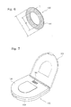
- Fig. 6 shows a modification of the rotary tool.
- This rotary tool 136 shown in Fig. 6 does not include a hub and is composed of only a cutting blade 144 which can be formed from an electrodeposition layer containing abrasive diamond grains.
- the rotary tool 136 can be advantageously formed by electrodepositing a metal and also accumulating abrasive diamond grains on one side of a metal annular plate and melting the entire annular plate.
- the rotary tool 136 shown in Fig. 6 can be fitted onto the rotary shaft of a dicer using a hub member (not shown) of an appropriate shape formed separately.
- the rotary tool 136 shown in Fig. 6 is composed of only the cutting blade 144 and does not include a hub. Therefore, when an indicator showing the characteristic properties, that is, thickness T, outer diameter D and inner diameter D' of the cutting blade 144 is to be provided on the rotary tool 136, it must be provided on the cutting blade 144. Meanwhile, as shown in Fig. 7, the rotary tool 136 is put on the market in a state of being stored in a storage case 162 molded out of an appropriate synthetic resin.
- the storage case 162 which may have a known shape per se has a storage base portion 164 and a cover portion 166 which can be opened and closed, the cover portion 166 can be opened and closed between a close position shown by a solid line and a close position shown by a two-dot chain line.
- the indicator 156 is provided at an appropriate site on the outer surface of the storage case 162 as shown in Fig. 7.
- the indicator 156 can be composed of a tag printed with a bar code.
- the rotary tool 36 shown in Fig. 3 and Fig. 4 is also put on the market in a state of being stored in the storage case (not shown). Therefore, in the case of the rotary tool 36 consisting of the hub 42 and the cutting blade 44 which are integrated with each other as shown in Fig. 3 and Fig. 4, the indicator 56 is provided on the storage case.
Landscapes
- Engineering & Computer Science (AREA)
- Mechanical Engineering (AREA)
- Chemical & Material Sciences (AREA)
- Ceramic Engineering (AREA)
- Inorganic Chemistry (AREA)
- Dicing (AREA)
- Polishing Bodies And Polishing Tools (AREA)
- Workshop Equipment, Work Benches, Supports, Or Storage Means (AREA)
- Details Of Cutting Devices (AREA)
- Turning (AREA)
- Sawing (AREA)
- Packaging Of Annular Or Rod-Shaped Articles, Wearing Apparel, Cassettes, Or The Like (AREA)
Claims (8)
- Kombination aus einem Drehwerkzeug, beinhaltend eine Schneidklinge bzw. ein Schneidblatt (44) und einen Speicherbehälter (162) zum Speichern des Drehwerkzeugs (36), wobei
der Speicherbehälter (162) einen Indikator (156) aufweist, der die charakteristischen Eigenschaften der Schneidklinge (44) anzeigt, dadurch gekennzeichnet, daß
die Schneidklinge (44) wie eine dünne ringförmige Platte geformt ist und
die charakteristischen Eigenschaften die Dicke (T) der Schneidklinge (44), den Außendurchmesser (D) der Schneidklinge (44) und den Innendurchmesser (D') der Schneidklinge (44) beinhalten. - Kombination nach Anspruch 1, wobei das Drehwerkzeug (36) aus nur einer dünnen ringförmigen plattenartigen Schneidklinge (44) zusammengesetzt ist.
- Kombination nach einem der Ansprüche 1 oder 2, wobei der Indikator (156) ein Strichcode ist, welcher vorzugsweise auf einem Aufkleber bzw. einem Etikett gedruckt ist, der bzw. das an dem Speicherbehälter (162) festgelegt ist.
- Kombination nach einem der Ansprüche 1 bis 3, wobei die Schneidklinge (44) aus einer Elektroabscheideschicht zusammengesetzt ist, die Diamantschleifkörner enthält und ähnlich einer dünnen ringförmigen Platte geformt ist.
- Schneidvorrichtung unter Verwendung einer Kombination aus einem Drehwerkzeug und einem Speicherbehälter, umfassend eine Drehwelle (34), welche lösbar mit einem Drehwerkzeug (36) zusammengepaßt bzw. versehen ist, welches eine Schneidklinge bzw. ein Schneideblatt (44) beinhaltet und aus einem Speicherbehälter (162) entnommen ist, wobei
der Speicherbehälter (162) einen Indikator (156) aufweist, der die charakteristischen Eigenschaften der Schneidklinge (44) anzeigt, und Lesemittel zum Lesen des Indikators (156) zur Verfügung gestellt sind, dadurch gekennzeichnet, daß die Schneidklinge (44) ähnlich einer dünnen ringförmigen Klinge bzw. Schneide geformt ist und
die charakteristischen Eigenschaften die Dicke (T) der Schneidklinge (44), den Außendurchmesser (D) der Schneidklinge (44) und den Innendurchmesser (D') der Schneidklinge (44) beinhalten. - Schneidvorrichtung nach Anspruch 5, wobei das Drehwerkzeug (36) aus nur einer Schneidklinge (44) zusammengesetzt ist, die ähnlich einer dünnen ringförmigen Platte geformt ist.
- Schneidvorrichtung nach einem der Ansprüche 5 oder 6, wobei der Indikator (156) ein Strichcode ist, der vorzugsweise auf ein Etikett bzw. einen Aufkleber gedruckt ist, welches bzw. welcher an dem Speicherbehälter (162) festgelegt ist, und die Lesemittel ein Strichcodeleser sind.
- Schneidvorrichtung nach einem der Ansprüche 5 bis 7, wobei die Schneidklinge (44) aus einer Elektroabscheideschicht zusammengesetzt ist, die Diamantschleifkörner enthält, und ähnlich einer dünnen ringförmigen Platte geformt ist.
Applications Claiming Priority (3)
| Application Number | Priority Date | Filing Date | Title |
|---|---|---|---|
| JP31978199A JP4387010B2 (ja) | 1999-11-10 | 1999-11-10 | 切削装置 |
| JP31978199 | 1999-11-10 | ||
| EP00124230A EP1099511B1 (de) | 1999-11-10 | 2000-11-09 | Drehwerkzeug mit einem Schneidmesser und Schneidvorrichtung mit einem solchen Werkzeug |
Related Parent Applications (1)
| Application Number | Title | Priority Date | Filing Date |
|---|---|---|---|
| EP00124230A Division EP1099511B1 (de) | 1999-11-10 | 2000-11-09 | Drehwerkzeug mit einem Schneidmesser und Schneidvorrichtung mit einem solchen Werkzeug |
Publications (2)
| Publication Number | Publication Date |
|---|---|
| EP1155784A1 EP1155784A1 (de) | 2001-11-21 |
| EP1155784B1 true EP1155784B1 (de) | 2006-02-01 |
Family
ID=18114127
Family Applications (2)
| Application Number | Title | Priority Date | Filing Date |
|---|---|---|---|
| EP01118365A Expired - Lifetime EP1155784B1 (de) | 1999-11-10 | 2000-11-09 | Speicherbehälter für ein Drehwerkzeug mit einem Schneideblatt und Schneidevorrichtung zu dessen Anwendung |
| EP00124230A Expired - Lifetime EP1099511B1 (de) | 1999-11-10 | 2000-11-09 | Drehwerkzeug mit einem Schneidmesser und Schneidvorrichtung mit einem solchen Werkzeug |
Family Applications After (1)
| Application Number | Title | Priority Date | Filing Date |
|---|---|---|---|
| EP00124230A Expired - Lifetime EP1099511B1 (de) | 1999-11-10 | 2000-11-09 | Drehwerkzeug mit einem Schneidmesser und Schneidvorrichtung mit einem solchen Werkzeug |
Country Status (8)
| Country | Link |
|---|---|
| US (1) | US6659098B1 (de) |
| EP (2) | EP1155784B1 (de) |
| JP (1) | JP4387010B2 (de) |
| KR (1) | KR100588409B1 (de) |
| DE (2) | DE60009232T2 (de) |
| MY (1) | MY142528A (de) |
| SG (1) | SG97167A1 (de) |
| TW (1) | TW498399B (de) |
Families Citing this family (66)
| Publication number | Priority date | Publication date | Assignee | Title |
|---|---|---|---|---|
| JP2002359211A (ja) * | 2001-05-30 | 2002-12-13 | Disco Abrasive Syst Ltd | 切削機 |
| DE10136534B4 (de) * | 2001-07-26 | 2006-05-11 | Disco Hi-Tec Europe Gmbh | Wafer-Schneidemaschine |
| US7160173B2 (en) | 2002-04-03 | 2007-01-09 | 3M Innovative Properties Company | Abrasive articles and methods for the manufacture and use of same |
| US7089081B2 (en) | 2003-01-31 | 2006-08-08 | 3M Innovative Properties Company | Modeling an abrasive process to achieve controlled material removal |
| JP4981388B2 (ja) * | 2006-09-13 | 2012-07-18 | 株式会社ディスコ | 検査情報提供システム及び検査情報提供方法 |
| JP2009083016A (ja) * | 2007-09-28 | 2009-04-23 | Disco Abrasive Syst Ltd | 切削装置 |
| JP5122232B2 (ja) * | 2007-10-12 | 2013-01-16 | 株式会社ディスコ | 切削ブレード |
| JP2009241177A (ja) * | 2008-03-28 | 2009-10-22 | Disco Abrasive Syst Ltd | ブレード交換工具 |
| JP5295645B2 (ja) * | 2008-06-04 | 2013-09-18 | 株式会社ディスコ | 切削装置 |
| JP5457131B2 (ja) * | 2009-10-07 | 2014-04-02 | 株式会社ディスコ | ブレード交換装置 |
| TWI399821B (zh) * | 2009-11-23 | 2013-06-21 | Powertech Technology Inc | 半導體切割刀片模組、其放置架及使用方法 |
| JP5523212B2 (ja) * | 2010-06-16 | 2014-06-18 | 株式会社ディスコ | 切削ブレードの管理方法 |
| US10455682B2 (en) | 2012-04-04 | 2019-10-22 | Hypertherm, Inc. | Optimization and control of material processing using a thermal processing torch |
| US10486260B2 (en) | 2012-04-04 | 2019-11-26 | Hypertherm, Inc. | Systems, methods, and devices for transmitting information to thermal processing systems |
| JP2012066328A (ja) * | 2010-09-22 | 2012-04-05 | Disco Corp | ドレッシングボードおよびドレッシングボード収容ケース |
| EP2455186A1 (de) * | 2010-11-17 | 2012-05-23 | Schneider GmbH & Co. KG | Vorrichtung und Verfahren zum Bearbeiten einer optischen Linse mit automatischer Identifizierung der optischen Linse |
| EP2436482A1 (de) * | 2010-10-04 | 2012-04-04 | Schneider GmbH & Co. KG | Vorrichtung und Verfahren zum Bearbeiten einer optischen Linse |
| BR112013008209B1 (pt) * | 2010-10-04 | 2022-03-15 | Schneider Gmbh & Co. Kg | Dispositivo para trabalhar uma lente óptica, lente óptica e processo para trabalhar uma lente óptica |
| EP2455187A1 (de) | 2010-11-23 | 2012-05-23 | Schneider GmbH & Co. KG | Vorrichtung und Verfahren zum Bearbeiten einer optischen Linse |
| DE102012101478A1 (de) * | 2012-02-23 | 2013-08-29 | Rattunde & Co. Gmbh | Einlesen von Sägeblattdaten aus Codes |
| US10146976B2 (en) | 2012-03-01 | 2018-12-04 | Proper Digital LLC | Tooling system |
| US9292811B2 (en) | 2012-11-30 | 2016-03-22 | Proper Group International | System and method for automated tool management |
| US9740790B2 (en) | 2012-03-01 | 2017-08-22 | Proper Digital LLC | Tooling system |
| US9672460B2 (en) | 2012-04-04 | 2017-06-06 | Hypertherm, Inc. | Configuring signal devices in thermal processing systems |
| US11783138B2 (en) * | 2012-04-04 | 2023-10-10 | Hypertherm, Inc. | Configuring signal devices in thermal processing systems |
| US20150332071A1 (en) * | 2012-04-04 | 2015-11-19 | Hypertherm, Inc. | Configuring Signal Devices in Thermal Processing Systems |
| US9737954B2 (en) | 2012-04-04 | 2017-08-22 | Hypertherm, Inc. | Automatically sensing consumable components in thermal processing systems |
| JP5991874B2 (ja) * | 2012-07-26 | 2016-09-14 | 株式会社ディスコ | 加工装置 |
| TW201431634A (zh) * | 2013-02-01 | 2014-08-16 | Pard Hardware Ind Co Ltd | 工具的標識方法 |
| JP6202932B2 (ja) * | 2013-08-13 | 2017-09-27 | 株式会社ディスコ | ワッシャーブレード及びブレードケース |
| JP6101178B2 (ja) * | 2013-09-09 | 2017-03-22 | アルプス電気株式会社 | ハーフカット装置およびプリンタ |
| US9643273B2 (en) * | 2013-10-14 | 2017-05-09 | Hypertherm, Inc. | Systems and methods for configuring a cutting or welding delivery device |
| US12275082B2 (en) | 2013-11-13 | 2025-04-15 | Hypertherm, Inc. | Consumable cartridge for a plasma arc cutting system |
| US12521905B2 (en) | 2014-03-07 | 2026-01-13 | Hypertherm, Inc. | Liquid pressurization pump and systems with data storage |
| US10786924B2 (en) | 2014-03-07 | 2020-09-29 | Hypertherm, Inc. | Waterjet cutting head temperature sensor |
| US9993934B2 (en) | 2014-03-07 | 2018-06-12 | Hyperthem, Inc. | Liquid pressurization pump and systems with data storage |
| US20150269603A1 (en) | 2014-03-19 | 2015-09-24 | Hypertherm, Inc. | Methods for Developing Customer Loyalty Programs and Related Systems and Devices |
| JP6327954B2 (ja) * | 2014-05-30 | 2018-05-23 | 株式会社ディスコ | 加工装置 |
| JP6406956B2 (ja) * | 2014-09-25 | 2018-10-17 | 株式会社ディスコ | 切削装置 |
| JP6388547B2 (ja) * | 2015-01-26 | 2018-09-12 | 株式会社ディスコ | 切削装置 |
| JP6417227B2 (ja) | 2015-01-27 | 2018-10-31 | 株式会社ディスコ | 切削ブレード及び切削装置並びにウエーハの加工方法 |
| JP6462422B2 (ja) | 2015-03-03 | 2019-01-30 | 株式会社ディスコ | 切削装置及びウエーハの加工方法 |
| JP2017168484A (ja) * | 2016-03-14 | 2017-09-21 | 株式会社東京精密 | ダイシング装置 |
| JP6643664B2 (ja) * | 2016-03-29 | 2020-02-12 | 株式会社東京精密 | ダイシング装置 |
| JP6913879B2 (ja) * | 2016-03-29 | 2021-08-04 | 株式会社東京精密 | ダイシング装置 |
| CN106624158A (zh) * | 2016-12-30 | 2017-05-10 | 苏州赛易特环保科技有限公司 | 一种多用型切削刀片 |
| CN106735357A (zh) * | 2016-12-30 | 2017-05-31 | 苏州赛易特环保科技有限公司 | 一种切削刀具 |
| MX2019009420A (es) | 2017-02-09 | 2019-10-02 | Hypertherm Inc | Anillo rotacional y elemento de contacto para un cartucho de antorcha de arco de plasma. |
| JP6851688B2 (ja) | 2017-04-21 | 2021-03-31 | 株式会社ディスコ | 加工工具の管理方法 |
| JP6957096B2 (ja) * | 2017-08-22 | 2021-11-02 | 株式会社ディスコ | ドレッシングボード、その使用方法及び切削装置 |
| JP6971093B2 (ja) * | 2017-08-30 | 2021-11-24 | 株式会社ディスコ | マルチブレード、加工方法 |
| EP3560656A1 (de) * | 2018-04-25 | 2019-10-30 | Martin Huber | System zur steuerung einer werkzeugmaschine |
| DE102018111343A1 (de) * | 2018-05-11 | 2019-11-14 | Amann Girrbach Ag | Anordnung mit einem Werkzeug und einer Verpackung |
| DE202018102658U1 (de) | 2018-05-11 | 2018-05-24 | Amann Girrbach Ag | Anordnung mit einem Werkzeug und einer Verpackung |
| DE202018104875U1 (de) * | 2018-08-24 | 2018-10-19 | Haimer Gmbh | Schrumpfgerät mit Futtererkennung und automatischer Spulenverstellung |
| JP6811411B2 (ja) * | 2019-06-19 | 2021-01-13 | 株式会社東京精密 | ダイシング装置 |
| JP7416581B2 (ja) * | 2019-08-20 | 2024-01-17 | 株式会社ディスコ | 切削方法及び切削装置 |
| JP7368424B2 (ja) * | 2019-12-25 | 2023-10-24 | 株式会社東京精密 | ダイシング装置 |
| CN111715151B (zh) * | 2020-06-19 | 2022-07-26 | 宁波巨化化工科技有限公司 | 一种丙醛合成反应器用调节装置 |
| JP7537921B2 (ja) * | 2020-06-24 | 2024-08-21 | 株式会社ディスコ | 切削装置 |
| JP7704536B2 (ja) * | 2021-01-28 | 2025-07-08 | 株式会社ディスコ | 切削装置 |
| JP7625350B2 (ja) * | 2021-03-23 | 2025-02-03 | 株式会社ディスコ | 切削装置 |
| JP7636250B2 (ja) * | 2021-04-19 | 2025-02-26 | 株式会社ディスコ | バーコードの読み取り方法及びバーコード読み取り装置 |
| CN118434523A (zh) | 2021-10-22 | 2024-08-02 | 环救援有限公司 | 用于安全地横切被困在附肢上的环状物的环状物切割器 |
| JP2024108199A (ja) | 2023-01-31 | 2024-08-13 | 株式会社ディスコ | 切削装置、読取装置 |
| USD1089340S1 (en) | 2023-06-22 | 2025-08-19 | Ring Rescue Inc. | Ring cutter |
Family Cites Families (17)
| Publication number | Priority date | Publication date | Assignee | Title |
|---|---|---|---|---|
| US4411107A (en) * | 1980-02-01 | 1983-10-25 | Disco Co., Ltd. | Grinding wheel for flat plates |
| JPS58102650A (ja) * | 1981-12-11 | 1983-06-18 | Toyota Motor Corp | 切削工具識別装置 |
| JPS58184727A (ja) * | 1982-04-23 | 1983-10-28 | Disco Abrasive Sys Ltd | シリコンウェ−ハの面を研削する方法 |
| US4922591A (en) * | 1984-03-20 | 1990-05-08 | Carboloy Inc. | Tool storage and changing system |
| JP2853124B2 (ja) * | 1988-02-19 | 1999-02-03 | ソニー株式会社 | 工具識別装置 |
| US4858302A (en) * | 1988-10-17 | 1989-08-22 | Precision Carbide Tool Co., Inc. | Tool deployment apparatus |
| JPH02172643A (ja) * | 1988-12-26 | 1990-07-04 | Toshiba Corp | 工具管理システム |
| US5613350A (en) * | 1992-12-24 | 1997-03-25 | Boucher; John N. | Method for packaging and handling fragile dicing blade |
| JP3223421B2 (ja) * | 1996-08-13 | 2001-10-29 | 株式会社東京精密 | ダイシング装置 |
| JP3630888B2 (ja) * | 1996-10-31 | 2005-03-23 | 株式会社ニデック | レンズ搬送装置と眼鏡レンズを搬送するための眼鏡レンズ用固定カップ及びレンズ搬送方法 |
| JP3213563B2 (ja) * | 1997-03-11 | 2001-10-02 | 株式会社スーパーシリコン研究所 | ノッチレスウェーハの製造方法 |
| JP3331931B2 (ja) * | 1997-11-12 | 2002-10-07 | ティーディーケイ株式会社 | ワークの加工制御方法 |
| ES2293670T3 (es) * | 1997-11-21 | 2008-03-16 | Nidek Co., Ltd. | Aparato de pulido de lentes. |
| US5842325A (en) * | 1997-12-11 | 1998-12-01 | Bausch & Lomb Incorporated | Method for labeling packages |
| US6029815A (en) * | 1998-08-11 | 2000-02-29 | Ali; Terry | Packaging substrate configured for connection to a rotary cutting wheel |
| TW437002B (en) * | 1998-11-06 | 2001-05-28 | Disco Abrasive System Ltd | CSP substrate dividing apparatus |
| JP2001024051A (ja) * | 1999-07-09 | 2001-01-26 | Tokyo Seimitsu Co Ltd | ウェーハ吸着パッド |
-
1999
- 1999-11-10 JP JP31978199A patent/JP4387010B2/ja not_active Expired - Lifetime
-
2000
- 2000-11-07 US US09/706,834 patent/US6659098B1/en not_active Expired - Lifetime
- 2000-11-07 SG SG200006367A patent/SG97167A1/en unknown
- 2000-11-07 TW TW089123469A patent/TW498399B/zh not_active IP Right Cessation
- 2000-11-09 MY MYPI20051456A patent/MY142528A/en unknown
- 2000-11-09 DE DE60009232T patent/DE60009232T2/de not_active Expired - Lifetime
- 2000-11-09 DE DE60025852T patent/DE60025852T2/de not_active Expired - Lifetime
- 2000-11-09 EP EP01118365A patent/EP1155784B1/de not_active Expired - Lifetime
- 2000-11-09 EP EP00124230A patent/EP1099511B1/de not_active Expired - Lifetime
- 2000-11-10 KR KR1020000066643A patent/KR100588409B1/ko not_active Expired - Lifetime
Also Published As
| Publication number | Publication date |
|---|---|
| DE60009232T2 (de) | 2005-02-24 |
| EP1099511A3 (de) | 2001-07-11 |
| EP1155784A1 (de) | 2001-11-21 |
| DE60025852T2 (de) | 2006-11-02 |
| TW498399B (en) | 2002-08-11 |
| MY142528A (en) | 2010-12-15 |
| US6659098B1 (en) | 2003-12-09 |
| JP4387010B2 (ja) | 2009-12-16 |
| EP1099511A2 (de) | 2001-05-16 |
| EP1099511B1 (de) | 2004-03-24 |
| JP2001144034A (ja) | 2001-05-25 |
| SG97167A1 (en) | 2003-07-18 |
| KR20010051586A (ko) | 2001-06-25 |
| DE60009232D1 (de) | 2004-04-29 |
| DE60025852D1 (de) | 2006-04-13 |
| KR100588409B1 (ko) | 2006-06-09 |
Similar Documents
| Publication | Publication Date | Title |
|---|---|---|
| EP1155784B1 (de) | Speicherbehälter für ein Drehwerkzeug mit einem Schneideblatt und Schneidevorrichtung zu dessen Anwendung | |
| CN102029657B (zh) | 刀具更换装置 | |
| TWI790387B (zh) | 切割裝置 | |
| US4649623A (en) | Chucking device for interchangeable holding of probe pins in a coordinate-measuring instrument | |
| EP0616364A1 (de) | Vorrichtung und verfahren zur herstellung von halbleiterscheiben | |
| CN101402228B (zh) | 切削装置 | |
| JP5892831B2 (ja) | 切削装置 | |
| US20090266217A1 (en) | Sheet cutting device and cutting method | |
| JP6646221B2 (ja) | ダイシング装置及びダイシング方法 | |
| JP6643664B2 (ja) | ダイシング装置 | |
| TWI408738B (zh) | 半導體晶圓處理膠帶捲裝體及使用該捲裝體之半導體晶圓處理膠帶貼著裝置,以及半導體晶圓加工處理裝置 | |
| JP4105905B2 (ja) | 切削装置の切削ブレード監視装置 | |
| JP2026063312A (ja) | ダイシング装置 | |
| CN102407488A (zh) | 修整板以及修整板收纳盒 | |
| EP0447083B1 (de) | Chipausstosssystem für Chipverbinder | |
| EP0203872A2 (de) | Gerät und Verfahren zur Zusammenstellung einer flexiblen Aufzeichnungsplatte | |
| JPH06326187A (ja) | ダイシング加工管理方法および加工品質管理システム | |
| JP6913879B2 (ja) | ダイシング装置 | |
| JPH05192922A (ja) | 薄溝加工機 | |
| JP2003163179A (ja) | ダイシング装置 | |
| EP0447087B1 (de) | Werkzeugauswechselsystem für Hybrid-Chipverbinder | |
| KR102893902B1 (ko) | 절삭 장치 | |
| US20240082968A1 (en) | Mounting method and cutting apparatus | |
| US7578723B2 (en) | Polishing tape and polishing device using same | |
| JP2001267193A (ja) | 半導体ウェーハ |
Legal Events
| Date | Code | Title | Description |
|---|---|---|---|
| PUAI | Public reference made under article 153(3) epc to a published international application that has entered the european phase |
Free format text: ORIGINAL CODE: 0009012 |
|
| AC | Divisional application: reference to earlier application |
Ref document number: 1099511 Country of ref document: EP |
|
| AK | Designated contracting states |
Kind code of ref document: A1 Designated state(s): DE IT Kind code of ref document: A1 Designated state(s): AT BE CH CY DE DK ES FI FR GB GR IE IT LI LU MC NL PT SE TR |
|
| AX | Request for extension of the european patent |
Free format text: AL;LT;LV;MK;RO;SI |
|
| 17P | Request for examination filed |
Effective date: 20011206 |
|
| AKX | Designation fees paid |
Free format text: DE IT |
|
| 17Q | First examination report despatched |
Effective date: 20030724 |
|
| GRAP | Despatch of communication of intention to grant a patent |
Free format text: ORIGINAL CODE: EPIDOSNIGR1 |
|
| GRAS | Grant fee paid |
Free format text: ORIGINAL CODE: EPIDOSNIGR3 |
|
| GRAA | (expected) grant |
Free format text: ORIGINAL CODE: 0009210 |
|
| AC | Divisional application: reference to earlier application |
Ref document number: 1099511 Country of ref document: EP Kind code of ref document: P |
|
| AK | Designated contracting states |
Kind code of ref document: B1 Designated state(s): DE IT |
|
| PG25 | Lapsed in a contracting state [announced via postgrant information from national office to epo] |
Ref country code: IT Free format text: LAPSE BECAUSE OF FAILURE TO SUBMIT A TRANSLATION OF THE DESCRIPTION OR TO PAY THE FEE WITHIN THE PRESCRIBED TIME-LIMIT;WARNING: LAPSES OF ITALIAN PATENTS WITH EFFECTIVE DATE BEFORE 2007 MAY HAVE OCCURRED AT ANY TIME BEFORE 2007. THE CORRECT EFFECTIVE DATE MAY BE DIFFERENT FROM THE ONE RECORDED. Effective date: 20060201 |
|
| REF | Corresponds to: |
Ref document number: 60025852 Country of ref document: DE Date of ref document: 20060413 Kind code of ref document: P |
|
| RAP2 | Party data changed (patent owner data changed or rights of a patent transferred) |
Owner name: DISCO CORPORATION |
|
| PLBE | No opposition filed within time limit |
Free format text: ORIGINAL CODE: 0009261 |
|
| STAA | Information on the status of an ep patent application or granted ep patent |
Free format text: STATUS: NO OPPOSITION FILED WITHIN TIME LIMIT |
|
| 26N | No opposition filed |
Effective date: 20061103 |
|
| PGFP | Annual fee paid to national office [announced via postgrant information from national office to epo] |
Ref country code: DE Payment date: 20191029 Year of fee payment: 20 |
|
| PGFP | Annual fee paid to national office [announced via postgrant information from national office to epo] |
Ref country code: IT Payment date: 20191108 Year of fee payment: 20 |
|
| REG | Reference to a national code |
Ref country code: DE Ref legal event code: R071 Ref document number: 60025852 Country of ref document: DE |