EP1154202A2 - Dispositif de commmande pour un brûleur - Google Patents
Dispositif de commmande pour un brûleur Download PDFInfo
- Publication number
- EP1154202A2 EP1154202A2 EP01110418A EP01110418A EP1154202A2 EP 1154202 A2 EP1154202 A2 EP 1154202A2 EP 01110418 A EP01110418 A EP 01110418A EP 01110418 A EP01110418 A EP 01110418A EP 1154202 A2 EP1154202 A2 EP 1154202A2
- Authority
- EP
- European Patent Office
- Prior art keywords
- signal
- control
- actuator
- control device
- ionization
- Prior art date
- Legal status (The legal status is an assumption and is not a legal conclusion. Google has not performed a legal analysis and makes no representation as to the accuracy of the status listed.)
- Granted
Links
Images
Classifications
-
- F—MECHANICAL ENGINEERING; LIGHTING; HEATING; WEAPONS; BLASTING
- F23—COMBUSTION APPARATUS; COMBUSTION PROCESSES
- F23N—REGULATING OR CONTROLLING COMBUSTION
- F23N5/00—Systems for controlling combustion
- F23N5/02—Systems for controlling combustion using devices responsive to thermal changes or to thermal expansion of a medium
- F23N5/12—Systems for controlling combustion using devices responsive to thermal changes or to thermal expansion of a medium using ionisation-sensitive elements, i.e. flame rods
- F23N5/123—Systems for controlling combustion using devices responsive to thermal changes or to thermal expansion of a medium using ionisation-sensitive elements, i.e. flame rods using electronic means
-
- F—MECHANICAL ENGINEERING; LIGHTING; HEATING; WEAPONS; BLASTING
- F23—COMBUSTION APPARATUS; COMBUSTION PROCESSES
- F23N—REGULATING OR CONTROLLING COMBUSTION
- F23N1/00—Regulating fuel supply
- F23N1/02—Regulating fuel supply conjointly with air supply
- F23N1/022—Regulating fuel supply conjointly with air supply using electronic means
-
- F—MECHANICAL ENGINEERING; LIGHTING; HEATING; WEAPONS; BLASTING
- F23—COMBUSTION APPARATUS; COMBUSTION PROCESSES
- F23N—REGULATING OR CONTROLLING COMBUSTION
- F23N2223/00—Signal processing; Details thereof
- F23N2223/04—Memory
-
- F—MECHANICAL ENGINEERING; LIGHTING; HEATING; WEAPONS; BLASTING
- F23—COMBUSTION APPARATUS; COMBUSTION PROCESSES
- F23N—REGULATING OR CONTROLLING COMBUSTION
- F23N2223/00—Signal processing; Details thereof
- F23N2223/08—Microprocessor; Microcomputer
-
- F—MECHANICAL ENGINEERING; LIGHTING; HEATING; WEAPONS; BLASTING
- F23—COMBUSTION APPARATUS; COMBUSTION PROCESSES
- F23N—REGULATING OR CONTROLLING COMBUSTION
- F23N2223/00—Signal processing; Details thereof
- F23N2223/36—PID signal processing
-
- F—MECHANICAL ENGINEERING; LIGHTING; HEATING; WEAPONS; BLASTING
- F23—COMBUSTION APPARATUS; COMBUSTION PROCESSES
- F23N—REGULATING OR CONTROLLING COMBUSTION
- F23N2223/00—Signal processing; Details thereof
- F23N2223/44—Optimum control
-
- F—MECHANICAL ENGINEERING; LIGHTING; HEATING; WEAPONS; BLASTING
- F23—COMBUSTION APPARATUS; COMBUSTION PROCESSES
- F23N—REGULATING OR CONTROLLING COMBUSTION
- F23N2225/00—Measuring
- F23N2225/26—Measuring humidity
- F23N2225/30—Measuring humidity measuring lambda
-
- F—MECHANICAL ENGINEERING; LIGHTING; HEATING; WEAPONS; BLASTING
- F23—COMBUSTION APPARATUS; COMBUSTION PROCESSES
- F23N—REGULATING OR CONTROLLING COMBUSTION
- F23N2227/00—Ignition or checking
- F23N2227/20—Calibrating devices
-
- F—MECHANICAL ENGINEERING; LIGHTING; HEATING; WEAPONS; BLASTING
- F23—COMBUSTION APPARATUS; COMBUSTION PROCESSES
- F23N—REGULATING OR CONTROLLING COMBUSTION
- F23N2233/00—Ventilators
- F23N2233/06—Ventilators at the air intake
- F23N2233/08—Ventilators at the air intake with variable speed
-
- F—MECHANICAL ENGINEERING; LIGHTING; HEATING; WEAPONS; BLASTING
- F23—COMBUSTION APPARATUS; COMBUSTION PROCESSES
- F23N—REGULATING OR CONTROLLING COMBUSTION
- F23N2235/00—Valves, nozzles or pumps
- F23N2235/12—Fuel valves
- F23N2235/16—Fuel valves variable flow or proportional valves
Definitions
- the invention relates to a control device for a burner, which burner in a Flame region of the burner arranged ionization electrode, and an actuator, which is the fuel supply amount or the air supply amount depending on one Control signal influenced.
- Ionization electrodes have long been used for flame monitoring in burners used.
- the ratio of the amount of air to the amount of fuel is often Called lambda, for each power requirement either by a controller or by a Control with sensors coordinated.
- lambda is intended for everyone Power requirement may be slightly above stoichiometric 1, for example 1.3.
- Air-controlled burners unlike controlled burners, react to external influences which change the combustion. They therefore have a higher efficiency and therefore one higher efficiency as well as lower pollutant emissions and thus a lower one Ecological damage.
- Rapid changes in the fuel supply or air supply are typically caused by abrupt changes in the power requirement.
- control devices according to IT-95U000566 and EP-A1-909922 contribute If rapid changes in performance occur, control is based on the stored Characteristic curve, but compensate for their imperfection in that they show the latest status of the Control signal first at a constant distance along the characteristic to a new value move.
- EP-A2-806610 developed control devices which also have stored a characteristic curve for the control signal.
- the characteristic curve serves also basically to pre-control the control signal in the event of rapid changes in power, while the ionization current is still lagging behind the facts.
- the latter control devices include one downstream of the ionization electrode Ionization evaluator, which generates an ionization signal, a control unit in which characteristic data for determining a first behavior of the actuator, which are at least stored temporarily generates a first control signal, and a controller, which the above Control signal at least temporarily depending on the ionization signal and at least temporarily generated depending on the first control signal.
- Control unit at least temporarily generates a second control signal and the controller that Control signal generated at least temporarily depending on the second control signal.
- control device can be constructed in such a way that it itself, when detected suitable conditions, an adjustment procedure for the acquisition of new characteristic data is carried out.
- an occasional or regular recalibration takes place, for any creeping changes in the control system, such as wear or contamination of the Ionization electrode to compensate.
- the Control characteristics can be determined automatically, even for gases using the preset Characteristic curves are not recorded.
- the characteristic data can, for example, be used as the constants in a polynomial development up to third order.
- the one approximately represented by the polynomial development Function defines a relationship between an input parameter and the control signal.
- the requested power serves as input parameter for the control curves, either in the form of a manipulated variable or a measured variable that corresponds to the power, for example the fan speed.
- a manipulated variable for example the fan speed.
- Control curves are used, e.g. B. temperature signals of all kinds such as burner temperature, Flow and return temperature, etc. Further examples are a pressure difference measured value Determination of gas or air volume flow, a gas or air volume flow meter, or directly the control signal for operating a gas valve or an oil pump.
- the first and the second behavior of the actuator advantageously depend on input parameters which represent the same size.
- the level of performance requested, or another physical size, the control unit by means of a single input parameter, such as the manipulated variable of the fan speed, or by means of input parameters of different types, such as The manipulated variable and the measured variable of the fan speed are fed.
- Burners are often equipped with a temperature sensor for the boiler temperature.
- a Change in the energy content of the fuel supplied has a change in According to boiler temperature.
- the manipulated variable is, for example Fan speed the first input parameter, and the temporal change in the boiler temperature the second.
- Characteristic data have been stored which indicate a first desired behavior of the Actuator with different performances, but fixed energy content of the fuel and determine fixed other influences. Characteristic data have also been saved, which one second behavior with different energy contents and this time determine fixed performance.
- control device uses boiler temperature changes to determine which do not correspond to the course of the manipulated variable of the fan speed, any Changes in the current energy content of the fuel supplied and generated by means of Characteristic data for the second behavior and considering the ionization signal corrected performance-related control curve.
- the control signal is in the case of a dynamic Power change the corrected control curve, for example, at a constant distance consequences.
- Burners of various types are possible as burners, for example premix gas burners or atmospheric burners with and without auxiliary fans.
- At atmospheric Burners without auxiliary fans can use the air volume flow z. B. via an air flap or the like. to be controlled.
- the controller at least generates the control signal temporarily by processing the control signals and the controller determines the processing at least temporarily depending on the ionization signal.
- control unit generates in one quasi-stable state no control signals.
- the control device then makes a clean one Regulation via the ionization signal. But as soon as a quick change of state occurs, switches the control device to the quickly reacting and precise control by a Processing the control signals around. How the control signals are processed is for example, previously determined by the ionization signal and remains throughout Steering period equal.
- the control system is only replaced by a control system when the State has calmed down and the ionization signal has lagged behind the current state.
- the control signals are generated permanently and both carry them the control signals and the ionization signal continuously contribute to the control signal. Mixed variants are also possible.
- controller at least temporarily Control signals weighted and added and that the controller at least temporarily the weighting determined depending on the ionization signal.
- the controller dampens rapid fluctuations in the Ionization signal compared to slow fluctuations before processing the Control signals.
- the controller has a low-pass filter for the ionization signal or equipped for a follow-up signal generated by processing, or with a Integrating unit for the ionization signal or for a subsequent signal generated by processing.
- control unit also contains characteristic data Determination of a behavior of the ionization signal stored, generates the control unit at least temporarily a setpoint signal and the controller generates the control signal at least temporarily depending on the setpoint signal.
- the controller is advantageous with a Comparison unit equipped, which at least temporarily the setpoint signal or by Processing generated sequence signal subtracted from the ionization signal.
- the controller can generate the control signal so that the ionization signal is directed to the Setpoint signal is regulated. This difference can be achieved by means of the above-mentioned integration unit be regulated to zero.
- Another embodiment of the invention relates to the stored characteristic data. That is advantageous first behavior of the actuator during burner operation with a first fuel been determined, and the second behavior of the actuator during burner operation a different second fuel in terms of energy content, especially if the specific energy content of one fuel is at least 5% higher than that of another Is fuel.
- the characteristic data for determining the two behavior of the Actuator result from measurements. Alternatively, only the characteristic data for the first behavior of the actuator determined based on measurement results. The key data for that second behaviors are then calculated from these. This is only possible if a specialist an appropriate knowledge of the behavior of the actuator among the different ones Circumstances.
- the characteristic data for the second Behavior instead of using burner-specific measurements based on professional knowledge determined on the fuel mixtures supplied in practice.
- the invention also relates to a method for setting an inventive control device.
- a burner with an inventive control device is first and equipped with additional sensors to determine the quality of the combustion. Then one operates the burner with a first fuel with a certain energy content different performance values each with different actuator positions, whereby one from determines the desired actuator status for each performance value from the sensor results. Out The desired actuator levels are used to determine the first behavior of the actuator. Then you run the burner with a second fuel a different energy content with different performance values different actuator levels, taking from the sensor results for each Performance value determines a desired actuator status, and now provides the desired Final control element characteristics to determine the second behavior of the final control element. Optionally, you repeat these steps for a third or even more fuels. Finally, the identified data are stored in one or more control devices saved. As described above, there are advantages to being specific Energy content of one fuel is at least 5% higher than that of another fuel.
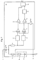
- FIG. 1 schematically shows the functional principle of an ionization evaluator 14 in a control device according to the invention.
- the flame 1 is represented by a diode 1a and a resistor 1b.
- An AC voltage of, for example, 230V is applied via L and N. If a flame 1 is present, a larger current flows in the positive half-wave than in the negative half-wave due to the flame diode 1a through the block capacitor 3. This forms a positive DC voltage U B at the block capacitor 3 between L and a resistor 2 attached for the purpose of protection against contact.
- a decoupling resistor 4 therefore flows a direct current from N to the block capacitor 3.
- the level of the direct current depends on U B and thus directly on the flame resistance 1b.
- the flame resistor 1b also influences the alternating current through the decoupling resistor 4, but to a different degree compared to the direct current.
- a direct current and an alternating current thus flow through the resistor 4 as described above.
- the resistor 4 is now followed by a high pass 5 and a low pass 6.
- the high-pass filter 5 filters out the alternating current and blocks the direct voltage component.
- the low-pass filter filters out the DC voltage component, which is dependent on the flame resistance 1b, and essentially blocks the AC current.
- the alternating current flowing from the high pass 5 is amplified in an amplifier 7 and a reference voltage U Ref is added.
- the direct current flowing from the high pass 6 is amplified with possibly small alternating current components and the reference voltage U Ref is added.
- the AC voltage emerging from the amplifier 7 and the DC voltage emerging from the amplifier 8 compared with one another and a pulse width modulated (PWM) signal generated. If the amplitude of the mains voltage changes, see above AC voltage and DC voltage change in the same ratio, the PWM signal does not change.
- the monoflop 11 is triggered such that the pulse sequence output from the comparator 10 comes faster than the pulse duration of the monoflop. This means that if there is no flame, a 1 constantly appears at the output of the monoflop. If there is a flame, the monoflop is not triggered and a 0 permanently appears at the output.
- the retriggerable monoflop 11 thus forms a " missing pulse detector", which converts the dynamic on / off signal into a static on / off signal.
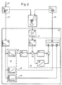
- FIG. 2 shows a block diagram of a control device 15 according to the invention.
- the ionization electrode 16 projects into the flame 1.
- the gas valve 17 is controlled by the control signal 18 in a direct or indirect manner, for example via a motor.
- a mechanical pressure regulator may still be connected.
- An air blower 19 is driven to a speed, which is used here as an input parameter becomes.
- the speed corresponds to a power requirement 22.
- the speed signal 20 is about a filter 21 led to the control unit 23, which as a program part to run in one Microprocessor has been designed.
- Characteristic data are stored there, which are the characteristic curves define a first and a second control signal 24 and 25.
- the controller 26 weights and adds the two control signals and thus determines the control signal 18. This processing of the Control signals depend on the ionization signal 13.
- the ionization signal 13 is first smoothed by the controller 26 by means of a low-pass filter 27 in order to To suppress glitches and flickering.
- a comparison unit 28 one of the Control unit 23 generates setpoint signal 30, which is guided via a correction unit 29 subtracted.
- the sequence signal of this processing of the ionization signal is converted by a Proportional controller 31 and a parallel integrating unit 32 determines an internal control value x, which weights the two control signals 24 and 25 and thus finely regulates the control signal 18.
- the control value x can alternatively be a PID controller or a status controller the following signal are generated.
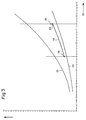
- FIG. 3 shows how the control signal 18 depends on a control device 15 according to the invention runs from the speed signal 20.
- the characteristic curves of the control signals 24 and 25 each relate to one Fuel gas with a fairly low or rather high calorific value.
Landscapes
- Engineering & Computer Science (AREA)
- Chemical & Material Sciences (AREA)
- Combustion & Propulsion (AREA)
- Mechanical Engineering (AREA)
- General Engineering & Computer Science (AREA)
- Regulation And Control Of Combustion (AREA)
- Control Of Combustion (AREA)
Applications Claiming Priority (4)
| Application Number | Priority Date | Filing Date | Title |
|---|---|---|---|
| DE10023265 | 2000-05-12 | ||
| DE10023265 | 2000-05-12 | ||
| DE10025769A DE10025769A1 (de) | 2000-05-12 | 2000-05-26 | Regeleinrichtung für einen Brenner |
| DE10025769 | 2000-05-26 |
Publications (4)
| Publication Number | Publication Date |
|---|---|
| EP1154202A2 true EP1154202A2 (fr) | 2001-11-14 |
| EP1154202A3 EP1154202A3 (fr) | 2003-05-14 |
| EP1154202B1 EP1154202B1 (fr) | 2004-06-16 |
| EP1154202B2 EP1154202B2 (fr) | 2009-12-09 |
Family
ID=26005646
Family Applications (1)
| Application Number | Title | Priority Date | Filing Date |
|---|---|---|---|
| EP01110418A Expired - Lifetime EP1154202B2 (fr) | 2000-05-12 | 2001-04-27 | Dispositif de commmande pour un brûleur |
Country Status (7)
| Country | Link |
|---|---|
| US (1) | US6537059B2 (fr) |
| EP (1) | EP1154202B2 (fr) |
| JP (1) | JP4897150B2 (fr) |
| KR (1) | KR100887418B1 (fr) |
| AT (1) | ATE269515T1 (fr) |
| DE (2) | DE10025769A1 (fr) |
| DK (1) | DK1154202T4 (fr) |
Cited By (12)
| Publication number | Priority date | Publication date | Assignee | Title |
|---|---|---|---|---|
| EP1396681A1 (fr) * | 2002-09-04 | 2004-03-10 | Siemens Building Technologies AG | Regulateur de brûleur et procédé pour ajuster un regulateur de brûleur |
| DE102011111453A1 (de) * | 2011-08-30 | 2013-02-28 | Robert Bosch Gmbh | Verfahren zur Luftzahleinstellung bei einem Heizgerät |
| EP2871473A1 (fr) * | 2013-11-07 | 2015-05-13 | Robert Bosch Gmbh | Capteur d'ionisation |
| WO2017060135A1 (fr) * | 2015-10-07 | 2017-04-13 | Bosch Termotecnologia S.A. | Dispositif pour appareil de chauffage et procédé permettant de faire fonctionner un dispositif pour appareil de chauffage |
| EP3290800A1 (fr) * | 2016-09-02 | 2018-03-07 | Robert Bosch GmbH | Procédé d'actualisation d'une caractéristique dans un système de chauffage ainsi qu'une unité de commande et système de chauffage |
| EP3663648A1 (fr) | 2018-12-05 | 2020-06-10 | Vaillant GmbH | Procédé et dispositif de régulation du rapport de mélange de l'air de combustion et de gaz de combustion dans un processus de combustion |
| DE102019101329A1 (de) | 2019-01-18 | 2020-07-23 | Vaillant Gmbh | Verfahren und Vorrichtung zur Regelung des Mischungsverhältnisses von Verbrennungsluft und Brenngas bei einem Verbrennungsprozess |
| DE102021214839A1 (de) | 2021-03-15 | 2022-09-15 | Siemens Aktiengesellschaft | Flammenüberwachung mit Temperatursensor |
| EP4060233A1 (fr) | 2021-03-16 | 2022-09-21 | Siemens Aktiengesellschaft | Détection de la capacité et régulation du facteur d'air au moyen des capteurs dans le foyer |
| DE102021121027A1 (de) | 2021-08-12 | 2023-02-16 | Vaillant Gmbh | Verfahren und Anordnung zum sicheren Betreiben und Regeln eines Verbrennungsprozesses in einem Heizgerät für die Verbrennung von Wasserstoff |
| EP4283196A1 (fr) | 2022-05-23 | 2023-11-29 | Siemens Aktiengesellschaft | Commande d'un rapport de mélange |
| EP4397908A1 (fr) | 2023-01-06 | 2024-07-10 | Siemens Aktiengesellschaft | Régulation de quantité de carburant et/ou régulation de quantité d'air |
Families Citing this family (17)
| Publication number | Priority date | Publication date | Assignee | Title |
|---|---|---|---|---|
| DE10023273A1 (de) * | 2000-05-12 | 2001-11-15 | Siemens Building Tech Ag | Messeinrichtung für eine Flamme |
| US20070006865A1 (en) * | 2003-02-21 | 2007-01-11 | Wiker John H | Self-cleaning oven |
| DE10341543A1 (de) * | 2003-09-09 | 2005-04-28 | Honeywell Bv | Regelungsverfahren für Gasbrenner |
| US20050208443A1 (en) * | 2004-03-17 | 2005-09-22 | Bachinski Thomas J | Heating appliance control system |
| US9585400B2 (en) | 2004-03-23 | 2017-03-07 | The Middleby Corporation | Conveyor oven apparatus and method |
| US8087407B2 (en) | 2004-03-23 | 2012-01-03 | Middleby Corporation | Conveyor oven apparatus and method |
| DE102004055716C5 (de) * | 2004-06-23 | 2010-02-11 | Ebm-Papst Landshut Gmbh | Verfahren zur Regelung einer Feuerungseinrichtung und Feuerungseinrichtung (Elektronischer Verbund I) |
| US20080092754A1 (en) * | 2006-10-19 | 2008-04-24 | Wayne/Scott Fetzer Company | Conveyor oven |
| US8075304B2 (en) | 2006-10-19 | 2011-12-13 | Wayne/Scott Fetzer Company | Modulated power burner system and method |
| DE102007018122B4 (de) | 2007-04-16 | 2013-10-17 | Viessmann Werke Gmbh & Co Kg | Flammenüberwachungsvorrichtung mit einer Spannungserzeugungs- und Messanordnung und Verfahren zum Überwachen eines Brenners mittels der Flammenüberwachungsvorrichtung |
| EP2020572B1 (fr) * | 2007-07-31 | 2012-12-26 | Sit la Precisa S.p.a. | Dispositif automatique pour l'allumage et le contrôle d'un appareil à gaz et procédé de commande correspondant |
| PL383941A1 (pl) * | 2007-12-03 | 2009-06-08 | Witold Kowalewski | Kocioł rusztowy, sposób modernizacji kotła rusztowego oraz sposób likwidowania szkodliwych przedmuchów powietrza, nie biorącego udziału w procesie spalania w kotle rusztowym |
| US8839714B2 (en) | 2009-08-28 | 2014-09-23 | The Middleby Corporation | Apparatus and method for controlling a conveyor oven |
| AT510002B1 (de) * | 2010-12-20 | 2012-01-15 | Vaillant Group Austria Gmbh | Verfahren zur regelung eines gas-/luftgemisches |
| DE102019114919A1 (de) * | 2019-06-04 | 2020-12-10 | Ebm-Papst Landshut Gmbh | Verfahren zur Regelung eines brenngasbetriebenen Heizgerätes |
| KR102504772B1 (ko) * | 2019-12-12 | 2023-03-02 | 주식회사 경동나비엔 | 물 가열기 및 이를 제어하는 방법 |
| DE102021113220A1 (de) | 2021-05-21 | 2022-11-24 | Vaillant Gmbh | Verfahren zur Überwachung des Betriebes eines Heizgerätes, Heizgerät sowie Computerprogramm und computerlesbares Medium |
Citations (4)
| Publication number | Priority date | Publication date | Assignee | Title |
|---|---|---|---|---|
| DE3937290A1 (de) | 1988-11-10 | 1990-05-17 | Vaillant Joh Gmbh & Co | Verfahren und einrichtung zur herstellung eines einer verbrennung zuzufuehrenden brennstoff-verbrennungsluft-gemisches |
| ITMI950566U1 (it) | 1995-07-27 | 1997-01-27 | Beretta A Ing Spa | Sistema di controllo aria-gas per bruciatori a basse emissioni su caldaie murali a gas con camera di combustione stagna |
| EP0806610A2 (fr) | 1996-05-09 | 1997-11-12 | STIEBEL ELTRON GmbH & Co. KG | Procédé et dispositif pour le fonctionnement d'un brûleur à gaz |
| EP0909922A1 (fr) | 1997-10-17 | 1999-04-21 | IABER S.p.A. | Système de commande combinée à gaz et à air pour commander la combustion d'une chaudière à gaz |
Family Cites Families (6)
| Publication number | Priority date | Publication date | Assignee | Title |
|---|---|---|---|---|
| US4588372A (en) * | 1982-09-23 | 1986-05-13 | Honeywell Inc. | Flame ionization control of a partially premixed gas burner with regulated secondary air |
| GB9400289D0 (en) * | 1994-01-08 | 1994-03-09 | Carver & Co Eng | Burner control apparatus |
| DE59604283D1 (de) * | 1995-10-25 | 2000-03-02 | Stiebel Eltron Gmbh & Co Kg | Verfahren und Schaltung zur Regelung eines Gasbrenners |
| DE19632983C2 (de) † | 1996-08-16 | 1999-11-04 | Stiebel Eltron Gmbh & Co Kg | Regeleinrichtung für einen Gasbrenner |
| DE19831648B4 (de) † | 1998-07-15 | 2004-12-23 | Stiebel Eltron Gmbh & Co. Kg | Verfahren zur funktionalen Adaption einer Regelelektronik an ein Gasheizgerät |
| US6299433B1 (en) * | 1999-11-05 | 2001-10-09 | Gas Research Institute | Burner control |
-
2000
- 2000-05-26 DE DE10025769A patent/DE10025769A1/de not_active Withdrawn
-
2001
- 2001-04-26 JP JP2001128588A patent/JP4897150B2/ja not_active Expired - Lifetime
- 2001-04-27 DK DK01110418.9T patent/DK1154202T4/da active
- 2001-04-27 EP EP01110418A patent/EP1154202B2/fr not_active Expired - Lifetime
- 2001-04-27 AT AT01110418T patent/ATE269515T1/de not_active IP Right Cessation
- 2001-04-27 DE DE50102575T patent/DE50102575D1/de not_active Expired - Lifetime
- 2001-05-07 US US09/850,529 patent/US6537059B2/en not_active Expired - Lifetime
- 2001-05-11 KR KR1020010025779A patent/KR100887418B1/ko active IP Right Grant
Patent Citations (4)
| Publication number | Priority date | Publication date | Assignee | Title |
|---|---|---|---|---|
| DE3937290A1 (de) | 1988-11-10 | 1990-05-17 | Vaillant Joh Gmbh & Co | Verfahren und einrichtung zur herstellung eines einer verbrennung zuzufuehrenden brennstoff-verbrennungsluft-gemisches |
| ITMI950566U1 (it) | 1995-07-27 | 1997-01-27 | Beretta A Ing Spa | Sistema di controllo aria-gas per bruciatori a basse emissioni su caldaie murali a gas con camera di combustione stagna |
| EP0806610A2 (fr) | 1996-05-09 | 1997-11-12 | STIEBEL ELTRON GmbH & Co. KG | Procédé et dispositif pour le fonctionnement d'un brûleur à gaz |
| EP0909922A1 (fr) | 1997-10-17 | 1999-04-21 | IABER S.p.A. | Système de commande combinée à gaz et à air pour commander la combustion d'une chaudière à gaz |
Cited By (15)
| Publication number | Priority date | Publication date | Assignee | Title |
|---|---|---|---|---|
| EP1396681A1 (fr) * | 2002-09-04 | 2004-03-10 | Siemens Building Technologies AG | Regulateur de brûleur et procédé pour ajuster un regulateur de brûleur |
| DE102011111453A1 (de) * | 2011-08-30 | 2013-02-28 | Robert Bosch Gmbh | Verfahren zur Luftzahleinstellung bei einem Heizgerät |
| EP2871473A1 (fr) * | 2013-11-07 | 2015-05-13 | Robert Bosch Gmbh | Capteur d'ionisation |
| WO2017060135A1 (fr) * | 2015-10-07 | 2017-04-13 | Bosch Termotecnologia S.A. | Dispositif pour appareil de chauffage et procédé permettant de faire fonctionner un dispositif pour appareil de chauffage |
| EP3290800A1 (fr) * | 2016-09-02 | 2018-03-07 | Robert Bosch GmbH | Procédé d'actualisation d'une caractéristique dans un système de chauffage ainsi qu'une unité de commande et système de chauffage |
| EP3663648A1 (fr) | 2018-12-05 | 2020-06-10 | Vaillant GmbH | Procédé et dispositif de régulation du rapport de mélange de l'air de combustion et de gaz de combustion dans un processus de combustion |
| DE102019101329A1 (de) | 2019-01-18 | 2020-07-23 | Vaillant Gmbh | Verfahren und Vorrichtung zur Regelung des Mischungsverhältnisses von Verbrennungsluft und Brenngas bei einem Verbrennungsprozess |
| DE102021214839A1 (de) | 2021-03-15 | 2022-09-15 | Siemens Aktiengesellschaft | Flammenüberwachung mit Temperatursensor |
| EP4060233A1 (fr) | 2021-03-16 | 2022-09-21 | Siemens Aktiengesellschaft | Détection de la capacité et régulation du facteur d'air au moyen des capteurs dans le foyer |
| EP4060232A1 (fr) | 2021-03-16 | 2022-09-21 | Siemens Aktiengesellschaft | Détection de la capacité et régulation du facteur d'air au moyen des capteurs dans le foyer |
| DE102021121027A1 (de) | 2021-08-12 | 2023-02-16 | Vaillant Gmbh | Verfahren und Anordnung zum sicheren Betreiben und Regeln eines Verbrennungsprozesses in einem Heizgerät für die Verbrennung von Wasserstoff |
| EP4141322A1 (fr) | 2021-08-12 | 2023-03-01 | Vaillant GmbH | Procédé et dispositif de fonctionnement et de commande sécurisés d'un processus de combustion dans un appareil de chauffage pour la combustion d'hydrogène |
| EP4283196A1 (fr) | 2022-05-23 | 2023-11-29 | Siemens Aktiengesellschaft | Commande d'un rapport de mélange |
| EP4283195A1 (fr) | 2022-05-23 | 2023-11-29 | Siemens Aktiengesellschaft | Commande d'un rapport de mélange |
| EP4397908A1 (fr) | 2023-01-06 | 2024-07-10 | Siemens Aktiengesellschaft | Régulation de quantité de carburant et/ou régulation de quantité d'air |
Also Published As
| Publication number | Publication date |
|---|---|
| KR100887418B1 (ko) | 2009-03-06 |
| DE10025769A1 (de) | 2001-11-15 |
| JP4897150B2 (ja) | 2012-03-14 |
| KR20010104275A (ko) | 2001-11-24 |
| DK1154202T3 (da) | 2004-10-25 |
| EP1154202B1 (fr) | 2004-06-16 |
| DE50102575D1 (de) | 2004-07-22 |
| ATE269515T1 (de) | 2004-07-15 |
| JP2001355841A (ja) | 2001-12-26 |
| DK1154202T4 (da) | 2010-04-26 |
| US20010051107A1 (en) | 2001-12-13 |
| EP1154202A3 (fr) | 2003-05-14 |
| EP1154202B2 (fr) | 2009-12-09 |
| US6537059B2 (en) | 2003-03-25 |
Similar Documents
| Publication | Publication Date | Title |
|---|---|---|
| EP1154202B1 (fr) | Dispositif de commmande pour un brûleur | |
| EP2594848B1 (fr) | Procédé de commande d'un appareil à combustion et appareil à combustion | |
| EP0770824B1 (fr) | Procédé et circuit pour commander un brûleur à gaz | |
| EP0806610B1 (fr) | Procédé pour le fonctionnement d'un brûleur à gaz | |
| DE4433425C2 (de) | Regeleinrichtung zum Einstellen eines Gas-Verbrennungsluft-Gemisches bei einem Gasbrenner | |
| EP1293727B1 (fr) | Appareil de commande d'un brûleur et méthode de réglage | |
| EP0030736A2 (fr) | Appareil de régulation de la quantité d'air de combustion pour un brûleur | |
| DE19539568C1 (de) | Verfahren und Schaltung zur Regelung eines Gasbrenners | |
| DE19618573C1 (de) | Verfahren und Einrichtung zum Betrieb eines Gasbrenners | |
| DE69308820T2 (de) | Verfahren und einrichtung zur brennstoff-luftregelung von brenner mit oberflächenverbrennung | |
| EP1331444B1 (fr) | Méthode de régulation d'un brûleur à gaz | |
| DE102004048986B4 (de) | Verfahren zur Regelung eines Gasbrenners | |
| EP1002997B1 (fr) | Procédé pour commander le rapport d'air / carburant d'un brûleur à gaz prémélangé complet | |
| EP2405198B1 (fr) | Procédé de calibration de régulation du rapport gaz combustible-air d'un brûleur à gaz combustible | |
| EP3029375B1 (fr) | Dispositif d'appareil de chauffage et procédé de fonctionnement d'un dispositif d'appareil de chauffage | |
| DE19839160B4 (de) | Verfahren und Schaltung zur Regelung eines Gasbrenners | |
| EP1396681A1 (fr) | Regulateur de brûleur et procédé pour ajuster un regulateur de brûleur | |
| EP0615095A1 (fr) | Automate à brûleur | |
| DE4312801A1 (de) | Verfahren zur Steuerung eines Gas-Gebläsebrenners | |
| DE10300602B4 (de) | Verfahren zur Regelung eines Gasbrenners | |
| DE4334625A1 (de) | Verfahren zum Konstanthalten der Leistung eines Wassererwärmers | |
| DE102011111453A1 (de) | Verfahren zur Luftzahleinstellung bei einem Heizgerät | |
| EP0614051B1 (fr) | Automate à brûleur | |
| DE3203675C2 (de) | Verfahren zur Regelung des Luftüberschusses an Feuerungen sowie Einrichtung zum Regeln des Luftüberschusses | |
| DE102004063992B4 (de) | Verfahren zur Steuerung einer Feuerungseinrichtung und Feuerungseinrichtung |
Legal Events
| Date | Code | Title | Description |
|---|---|---|---|
| PUAI | Public reference made under article 153(3) epc to a published international application that has entered the european phase |
Free format text: ORIGINAL CODE: 0009012 |
|
| 17P | Request for examination filed |
Effective date: 20010609 |
|
| AK | Designated contracting states |
Kind code of ref document: A2 Designated state(s): AT BE CH CY DE DK ES FI FR GB GR IE IT LI LU MC NL PT SE TR |
|
| AX | Request for extension of the european patent |
Free format text: AL;LT;LV;MK;RO;SI |
|
| PUAL | Search report despatched |
Free format text: ORIGINAL CODE: 0009013 |
|
| AK | Designated contracting states |
Designated state(s): AT BE CH CY DE DK ES FI FR GB GR IE IT LI LU MC NL PT SE TR |
|
| AX | Request for extension of the european patent |
Extension state: AL LT LV MK RO SI |
|
| GRAP | Despatch of communication of intention to grant a patent |
Free format text: ORIGINAL CODE: EPIDOSNIGR1 |
|
| AKX | Designation fees paid |
Designated state(s): AT BE CH CY DE DK ES FI FR GB GR IE IT LI LU MC NL PT SE TR |
|
| GRAS | Grant fee paid |
Free format text: ORIGINAL CODE: EPIDOSNIGR3 |
|
| GRAA | (expected) grant |
Free format text: ORIGINAL CODE: 0009210 |
|
| AK | Designated contracting states |
Kind code of ref document: B1 Designated state(s): AT BE CH CY DE DK ES FI FR GB GR IE IT LI LU MC NL PT SE TR |
|
| PG25 | Lapsed in a contracting state [announced via postgrant information from national office to epo] |
Ref country code: IE Free format text: LAPSE BECAUSE OF FAILURE TO SUBMIT A TRANSLATION OF THE DESCRIPTION OR TO PAY THE FEE WITHIN THE PRESCRIBED TIME-LIMIT Effective date: 20040616 Ref country code: FI Free format text: LAPSE BECAUSE OF FAILURE TO SUBMIT A TRANSLATION OF THE DESCRIPTION OR TO PAY THE FEE WITHIN THE PRESCRIBED TIME-LIMIT Effective date: 20040616 Ref country code: TR Free format text: LAPSE BECAUSE OF FAILURE TO SUBMIT A TRANSLATION OF THE DESCRIPTION OR TO PAY THE FEE WITHIN THE PRESCRIBED TIME-LIMIT Effective date: 20040616 |
|
| REG | Reference to a national code |
Ref country code: GB Ref legal event code: FG4D Free format text: NOT ENGLISH |
|
| REG | Reference to a national code |
Ref country code: CH Ref legal event code: EP |
|
| REF | Corresponds to: |
Ref document number: 50102575 Country of ref document: DE Date of ref document: 20040722 Kind code of ref document: P |
|
| REG | Reference to a national code |
Ref country code: IE Ref legal event code: FG4D Free format text: GERMAN |
|
| PG25 | Lapsed in a contracting state [announced via postgrant information from national office to epo] |
Ref country code: GR Free format text: LAPSE BECAUSE OF FAILURE TO SUBMIT A TRANSLATION OF THE DESCRIPTION OR TO PAY THE FEE WITHIN THE PRESCRIBED TIME-LIMIT Effective date: 20040916 |
|
| PG25 | Lapsed in a contracting state [announced via postgrant information from national office to epo] |
Ref country code: ES Free format text: LAPSE BECAUSE OF FAILURE TO SUBMIT A TRANSLATION OF THE DESCRIPTION OR TO PAY THE FEE WITHIN THE PRESCRIBED TIME-LIMIT Effective date: 20040927 |
|
| GBT | Gb: translation of ep patent filed (gb section 77(6)(a)/1977) |
Effective date: 20040906 |
|
| REG | Reference to a national code |
Ref country code: SE Ref legal event code: TRGR |
|
| REG | Reference to a national code |
Ref country code: DK Ref legal event code: T3 |
|
| REG | Reference to a national code |
Ref country code: IE Ref legal event code: FD4D |
|
| ET | Fr: translation filed | ||
| PLAQ | Examination of admissibility of opposition: information related to despatch of communication + time limit deleted |
Free format text: ORIGINAL CODE: EPIDOSDOPE2 |
|
| PLBQ | Unpublished change to opponent data |
Free format text: ORIGINAL CODE: EPIDOS OPPO |
|
| PLBI | Opposition filed |
Free format text: ORIGINAL CODE: 0009260 |
|
| PLAQ | Examination of admissibility of opposition: information related to despatch of communication + time limit deleted |
Free format text: ORIGINAL CODE: EPIDOSDOPE2 |
|
| PLAR | Examination of admissibility of opposition: information related to receipt of reply deleted |
Free format text: ORIGINAL CODE: EPIDOSDOPE4 |
|
| PLAX | Notice of opposition and request to file observation + time limit sent |
Free format text: ORIGINAL CODE: EPIDOSNOBS2 |
|
| PLBQ | Unpublished change to opponent data |
Free format text: ORIGINAL CODE: EPIDOS OPPO |
|
| PLAB | Opposition data, opponent's data or that of the opponent's representative modified |
Free format text: ORIGINAL CODE: 0009299OPPO |
|
| PG25 | Lapsed in a contracting state [announced via postgrant information from national office to epo] |
Ref country code: CY Free format text: LAPSE BECAUSE OF FAILURE TO SUBMIT A TRANSLATION OF THE DESCRIPTION OR TO PAY THE FEE WITHIN THE PRESCRIBED TIME-LIMIT Effective date: 20050427 Ref country code: LU Free format text: LAPSE BECAUSE OF NON-PAYMENT OF DUE FEES Effective date: 20050427 Ref country code: AT Free format text: LAPSE BECAUSE OF NON-PAYMENT OF DUE FEES Effective date: 20050427 |
|
| PG25 | Lapsed in a contracting state [announced via postgrant information from national office to epo] |
Ref country code: BE Free format text: LAPSE BECAUSE OF NON-PAYMENT OF DUE FEES Effective date: 20050430 Ref country code: MC Free format text: LAPSE BECAUSE OF NON-PAYMENT OF DUE FEES Effective date: 20050430 |
|
| 26 | Opposition filed |
Opponent name: STIEBEL ELTRON GMBH & CO.KG Effective date: 20050316 |
|
| R26 | Opposition filed (corrected) |
Opponent name: STIEBEL ELTRON GMBH & CO.KG Effective date: 20050316 |
|
| NLR1 | Nl: opposition has been filed with the epo |
Opponent name: STIEBEL ELTRON GMBH & CO.KG |
|
| NLR1 | Nl: opposition has been filed with the epo |
Opponent name: STIEBEL ELTRON GMBH & CO.KG |
|
| PLBB | Reply of patent proprietor to notice(s) of opposition received |
Free format text: ORIGINAL CODE: EPIDOSNOBS3 |
|
| BERE | Be: lapsed |
Owner name: *SIEMENS BUILDING TECHNOLOGIES A.G. Effective date: 20050430 |
|
| PLCK | Communication despatched that opposition was rejected |
Free format text: ORIGINAL CODE: EPIDOSNREJ1 |
|
| APBP | Date of receipt of notice of appeal recorded |
Free format text: ORIGINAL CODE: EPIDOSNNOA2O |
|
| APAH | Appeal reference modified |
Free format text: ORIGINAL CODE: EPIDOSCREFNO |
|
| APBQ | Date of receipt of statement of grounds of appeal recorded |
Free format text: ORIGINAL CODE: EPIDOSNNOA3O |
|
| REG | Reference to a national code |
Ref country code: CH Ref legal event code: PFA Owner name: SIEMENS BUILDING TECHNOLOGIES AG C-IPR Free format text: SIEMENS BUILDING TECHNOLOGIES AG#BELLERIVESTRASSE 36#8008 ZUERICH (CH) -TRANSFER TO- SIEMENS BUILDING TECHNOLOGIES AG C-IPR#GUBELSTRASSE 22#6300 ZUG (CH) |
|
| BERE | Be: lapsed |
Owner name: *SIEMENS BUILDING TECHNOLOGIES A.G. Effective date: 20050430 |
|
| PG25 | Lapsed in a contracting state [announced via postgrant information from national office to epo] |
Ref country code: PT Free format text: LAPSE BECAUSE OF NON-PAYMENT OF DUE FEES Effective date: 20041116 |
|
| APBU | Appeal procedure closed |
Free format text: ORIGINAL CODE: EPIDOSNNOA9O |
|
| RAP2 | Party data changed (patent owner data changed or rights of a patent transferred) |
Owner name: SIEMENS SCHWEIZ AG |
|
| NLT2 | Nl: modifications (of names), taken from the european patent patent bulletin |
Owner name: SIEMENS SCHWEIZ AG Effective date: 20090722 |
|
| PUAH | Patent maintained in amended form |
Free format text: ORIGINAL CODE: 0009272 |
|
| STAA | Information on the status of an ep patent application or granted ep patent |
Free format text: STATUS: PATENT MAINTAINED AS AMENDED |
|
| 27A | Patent maintained in amended form |
Effective date: 20091209 |
|
| AK | Designated contracting states |
Kind code of ref document: B2 Designated state(s): AT BE CH CY DE DK ES FI FR GB GR IE IT LI LU MC NL PT SE TR |
|
| REG | Reference to a national code |
Ref country code: CH Ref legal event code: AEN Free format text: AUFRECHTERHALTUNG DES PATENTES IN GEAENDERTER FORM |
|
| REG | Reference to a national code |
Ref country code: ES Ref legal event code: FD2A Effective date: 20050428 |
|
| NLR2 | Nl: decision of opposition |
Effective date: 20091209 |
|
| REG | Reference to a national code |
Ref country code: SE Ref legal event code: RPEO |
|
| REG | Reference to a national code |
Ref country code: NL Ref legal event code: T3 |
|
| REG | Reference to a national code |
Ref country code: DK Ref legal event code: T4 |
|
| REG | Reference to a national code |
Ref country code: CH Ref legal event code: PFUS Owner name: SIEMENS SCHWEIZ AG, CH Free format text: FORMER OWNER: SIEMENS BUILDING TECHNOLOGIES AG C-IPR, CH |
|
| REG | Reference to a national code |
Ref country code: CH Ref legal event code: PFUS Owner name: SIEMENS SCHWEIZ AG, CH Free format text: FORMER OWNER: SIEMENS BUILDING TECHNOLOGIES AG C-IPR, CH |
|
| REG | Reference to a national code |
Ref country code: DE Ref legal event code: R081 Ref document number: 50102575 Country of ref document: DE Owner name: SIEMENS SCHWEIZ AG, CH Free format text: FORMER OWNER: SIEMENS BUILDING TECHNOLOGIES AG, ZUERICH, CH Effective date: 20130506 |
|
| REG | Reference to a national code |
Ref country code: FR Ref legal event code: TP Owner name: SIEMENS SCHWEIZ AG, CH Effective date: 20131029 |
|
| REG | Reference to a national code |
Ref country code: FR Ref legal event code: PLFP Year of fee payment: 16 |
|
| REG | Reference to a national code |
Ref country code: FR Ref legal event code: PLFP Year of fee payment: 17 |
|
| REG | Reference to a national code |
Ref country code: FR Ref legal event code: PLFP Year of fee payment: 18 |
|
| PGFP | Annual fee paid to national office [announced via postgrant information from national office to epo] |
Ref country code: DE Payment date: 20200619 Year of fee payment: 20 Ref country code: FR Payment date: 20200410 Year of fee payment: 20 Ref country code: DK Payment date: 20200422 Year of fee payment: 20 Ref country code: NL Payment date: 20200402 Year of fee payment: 20 |
|
| PGFP | Annual fee paid to national office [announced via postgrant information from national office to epo] |
Ref country code: GB Payment date: 20200402 Year of fee payment: 20 Ref country code: IT Payment date: 20200427 Year of fee payment: 20 Ref country code: SE Payment date: 20200407 Year of fee payment: 20 |
|
| PGFP | Annual fee paid to national office [announced via postgrant information from national office to epo] |
Ref country code: CH Payment date: 20200702 Year of fee payment: 20 |
|
| REG | Reference to a national code |
Ref country code: DE Ref legal event code: R071 Ref document number: 50102575 Country of ref document: DE |
|
| REG | Reference to a national code |
Ref country code: NL Ref legal event code: MK Effective date: 20210426 |
|
| REG | Reference to a national code |
Ref country code: DK Ref legal event code: EUP Expiry date: 20210427 |
|
| REG | Reference to a national code |
Ref country code: CH Ref legal event code: PL |
|
| REG | Reference to a national code |
Ref country code: GB Ref legal event code: PE20 Expiry date: 20210426 |
|
| REG | Reference to a national code |
Ref country code: SE Ref legal event code: EUG |
|
| PG25 | Lapsed in a contracting state [announced via postgrant information from national office to epo] |
Ref country code: GB Free format text: LAPSE BECAUSE OF EXPIRATION OF PROTECTION Effective date: 20210426 |