EP1154078B1 - Apparatus for and a method of boring the ground - Google Patents
Apparatus for and a method of boring the ground Download PDFInfo
- Publication number
- EP1154078B1 EP1154078B1 EP01110402A EP01110402A EP1154078B1 EP 1154078 B1 EP1154078 B1 EP 1154078B1 EP 01110402 A EP01110402 A EP 01110402A EP 01110402 A EP01110402 A EP 01110402A EP 1154078 B1 EP1154078 B1 EP 1154078B1
- Authority
- EP
- European Patent Office
- Prior art keywords
- ground
- casing tube
- boring
- telescopic cylinder
- supporting frame
- Prior art date
- Legal status (The legal status is an assumption and is not a legal conclusion. Google has not performed a legal analysis and makes no representation as to the accuracy of the status listed.)
- Expired - Lifetime
Links
Images


Classifications
-
- E—FIXED CONSTRUCTIONS
- E02—HYDRAULIC ENGINEERING; FOUNDATIONS; SOIL SHIFTING
- E02D—FOUNDATIONS; EXCAVATIONS; EMBANKMENTS; UNDERGROUND OR UNDERWATER STRUCTURES
- E02D5/00—Bulkheads, piles, or other structural elements specially adapted to foundation engineering
- E02D5/22—Piles
- E02D5/34—Concrete or concrete-like piles cast in position ; Apparatus for making same
- E02D5/38—Concrete or concrete-like piles cast in position ; Apparatus for making same making by use of mould-pipes or other moulds
- E02D5/385—Concrete or concrete-like piles cast in position ; Apparatus for making same making by use of mould-pipes or other moulds with removal of the outer mould-pipes
-
- E—FIXED CONSTRUCTIONS
- E02—HYDRAULIC ENGINEERING; FOUNDATIONS; SOIL SHIFTING
- E02D—FOUNDATIONS; EXCAVATIONS; EMBANKMENTS; UNDERGROUND OR UNDERWATER STRUCTURES
- E02D7/00—Methods or apparatus for placing sheet pile bulkheads, piles, mouldpipes, or other moulds
- E02D7/20—Placing by pressure or pulling power
Definitions
- the present invention relates to ground-boring apparatus and a ground-boring method suited for the all-casing method.
- cast-in-place concrete pile technology has been widely used for making foundation piles at the construction site of a building, for example, in which each concrete pile is made by boring a hole in the ground, inserting a cage made of steel reinforcing bars into the hole, and pouring concrete into the hole.
- Various methods are known in the conventional cast-in-place concrete pile technology, including the earth drill method and all-casing method.
- the earth drill method is a method of making a hole in the ground using a cylindrical rotary bucket, or using a soil stabilizer to protect the wall of the hole. This method is suited for boring relatively hard ground mainly containing clay, for example.
- the all-casing method is a method of making a hole in the ground by driving a casing tube into the ground and digging inside the casing tube.
- This method allows boring even soft ground, such as reclaimed land. Since a plurality of casing tubes can be driven one on top of another, it is possible to make a long pile which will reach a deep bearing stratum. Moreover, since this method enables boring operation to be done even when there is an obstacle underground, it is frequently used in recent years.
- US-A-4 202 416 discloses a method for sinking a cased borehole for producing cased pile foundations.
- the method uses an apparatus comprising a crane, a drilling appliance capable of being lowered into the borehole and a tube extraction machine with double-acting lifting cylinders for increasing the drilling pressure and for extracting the drop tube after the pile has been concreted.
- the drilling appliance is capable of producing a borehole with a larger diameter that that of the drop tube and can be fixed to the drop tube by means of a clamping device for withstanding the torque of the motor used for driving the drilling tool.
- the drop tube is axially secured and is prevented from locating with respect to the ground, a section of borehole having a greater diameter than the diameter of the drop tube is drilled, and subsequently the axial securement of the drop tube is released so that the drop tube slides downwards by a length corresponding to the length of the section of borehole drilled.
- a commonly used technique in the all-casing method for inserting a casing tube into the ground is to drive the casing tube by pressure while turning it about its vertical axis using an all-round rotary boring machine.
- all-casing boring operation it is necessary to dig the ground inside the casing tube and remove soil from the inside of the casing tube.
- a hammer grab has conventionally been used as a tool for doing this task.
- the hammer grab has a problem that its digging and soil-discharging efficiency is rather poor, because it uses a pair of claw members which is operated in a narrow space within the casing tube to dig and pick up soil.
- the hammer grab also has a problem that it produces a high level of noise as it is repeatedly dropped during the boring operation.
- the hammer grab cannot level off the bottom of a hole, a cage which will serve as a core of a pile can not be set in a stable position, leading to a possibility of variations in the strength of finished concrete piles.
- a new drilling method is going to be put into practical use today, in which, instead of a hammer grab, a boring screw head is inserted into a casing tube to dig and remove soil at the same time.
- the boring screw head is raised and lowered along a leader which serves as a guide suspended in a vertical position from a base machine, so that boring operation is performed with the base machine held close to an all-round rotary boring machine in this drilling method.
- This new drilling method serves to dramatically improve the efficiency of digging and removing soil compared to the aforementioned hammer grab method.
- This drilling method has a problem that it can not be used for making a hole if there is an unlevelled area or obstacle between the base machine and a boring point, because the base machine must be located close to the boring point where the all-round rotary boring machine is installed. Furthermore, as the distance between the base machine and the boring point can not be made so large, the diameter of the all-round rotary boring machine is limited, making it impossible to bore a hole having a large diameter as a consequence.
- the vertically positioning accuracy of the boring screw head is affected by the horizontally positioning accuracy of the base machine, it is necessary to level off an area of the ground where the base machine is installed to achieve its highly accurate horizontal position.
- the base machine since the base machine is dedicated exclusively to boring operation, it is necessary to move it away and bring in an auxiliary crane as the need arises to perform hoisting operation, such as when handling a cage or inserting an additional casing tube.
- the present invention has been made in view of the aforementioned problems of the conventional cast-in-place concrete pile technology. Accordingly, it is an object of the invention to provide ground-boring apparatus and a ground-boring method which make it possible to efficiently bore a hole of a desired diameter regardless of ground conditions of a boring site without the need of a dedicated boring machine and thereby reduce the number of processes required for boring operation.
- a ground-boring apparatus is adapted for boring the ground within a casing tube and removing soil from the bored hole.
- the casing tube is driven into the ground by a casing tube pusher to prevent the ground from collapsing into a bored hole.
- the apparatus comprises an extensible telescopic cylinder to be suspended by a movable crane, a boring tool attached to the lower end of the telescopic cylinder, a supporting frame unit to be placed on the casing tube for holding the telescopic cylinder rotatably about its vertical axis, a driver provided on the supporting frame unit for turning the telescopic cylinder about its vertical axis, and an interlock device for joining the supporting frame unit and the casing tube to thereby ensure the rotation of the telescopic cylinder counteracting a reaction force exerted by the rotating telescopic cylinder.
- a method of boring the ground comprises the steps of driving a casing tube into the ground by a casing tube pusher to prevent the ground from collapsing into a bored hole, placing the aforementioned ground-boring apparatus suspended by a movable crane on the casing tube, fastening the casing tube to the supporting frame unit, and digging the ground within the casing tube while rotating the telescopic cylinder about its vertical axis and extending the telescopic cylinder according to the depth of the bored hole.
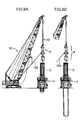
- FIG. 1 is an overall perspective view of a ground-boring system 1 according to an embodiment of the invention.
- the ground-boring system 1 is constructed mainly of a casing tube pusher machine 3 of the prior art for driving a casing tube 2 into the ground and a ground-boring machine 4 provided atop the casing tube 2 which is mounted in the casing tube pusher machine 3.
- the casing tube pusher machine 3 forces the casing tube 2 into the ground in a vertical position while turning it all round with a high torque to thereby prevent soil from collapsing into a bored hole.
- the casing tube pusher machine 3 comprises a base frame 5 to be placed in a horizontal position, on which a plurality of up/down cylinders 7 for raising and lowering an up/down frame 6 are vertically mounted.
- a plurality of hydraulic motors 8 are provided on the up/down frame 6 for turning the casing tube 2 about its vertical axis via planetary reduction gears 9.
- a weight (not shown) on the base frame 5 to fully counteract a reaction force exerted by the rotating casing tube 2 during boring operation.
- the ground-boring machine 4 need not necessarily be an all-round rotation type but may be a swing-motion type.
- the ground-boring machine 4 comprises an extensible kelly bar 10 of a telescopic structure having a plurality of overlapping cylindrical members and a supporting frame unit 11 which is placed immediately atop the casing tube 2 and holds a lower part of the extensible kelly bar 10.
- the extensible kelly bar 10 is suspended by its upper end by means of a wire rope 13 which is paid out from a movable crane 12 (hereinafter referred to simply as the crane 12).
- a cylindrical boring bucket (boring tool) 14 is connected to the lower end of the innermost cylindrical member 10c of the extensible kelly bar 10.
- the boring bucket 14 drills underlying bedrock strata, for example, with a plurality of boring bits embedded in the bottom end of the boring bucket 14 and accommodates excavated material in its inner space.
- the construction of this boring bucket 14 is conventional.
- a hinged bottom plate 14a on the bottom of the boring bucket 14 as shown in FIG. 2, and an operating rod 14b for opening the operating rod 14b extends downward onto its upper surface.
- a contact plate 14c at the upper end of the operating rod 14b as shown.
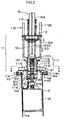
- FIG. 2 is an enlarged partially cutaway view showing the construction of the ground-boring machine 4.
- the supporting frame unit 11 holding the lower part of the extensible kelly bar 10 is constructed of a stationary frame 111 placed at an upper end 2a of the casing tube 2 and a movable frame 113 which holds the outermost cylindrical member 10a of the extensible kelly bar 10, the movable frame 113 being connected to the stationary frame 111 via a pair of hydraulic cylinders 112 vertically mounted on the stationary frame 111.
- a later-described inner cylindrical part 120 integrally attached to the movable frame 113 extends downward therefrom as illustrated.
- the stationary frame 111 includes the aforementioned outer cylindrical part 111a in which the inner cylindrical part 120 is inserted, the outer cylindrical part 111a having an upper flange portion 111b and a lower flange portion 111c radially protruding from upper and middle parts of the outer cylindrical part 111a, respectively.
- Four leg projections 111d extend from the lower flange portion 111c in a crisscross pattern in plan view. Of these leg projections 111d, two opposed leg projections 111d are individually fitted with clamping devices 114 which serve as means for acting against the reaction force exerted by the rotating casing tube 2.
- Each of the clamping devices 114 includes a clamping block 114a which is secured to the bottom of the relevant leg projection 111d.
- the upper end 2a of the casing tube 2 is fitted into a U-shaped gap formed in each clamping block 114a.
- Each of the clamping devices 114 further includes a pusher 114b which can move either backward or forward in the aforementioned U-shaped gap in the clamping block 114a in the directions of double arrow B shown in FIG. 2.
- the pusher 114b is moved back and forth by extending and retracting a rod 114d of a hydraulic cylinder 114c which is fixed to each clamping block 114a.
- the clamping devices 114 When the pushers 114b of the clamping devices 114 are moved forward, the clamping devices 114 firmly grip the upper end 2a of the casing tube 2, whereby the stationary frame 111 secures the casing tube 2. On the contrary, when the pushers 114b are moved backward, the clamping devices 114 release the upper end 2a of the casing tube 2, and the casing tube 2 is disengaged from the stationary frame 111.
- the clamping devices 114 are made movable back and forth in the directions of the double arrow B along respective guide rails 111c' formed on the bottom of the leg projections 111d radially extending from the lower flange portion 111c of the stationary frame 111. This allows the clamping devices 114 to be properly positioned according to the diameter of the casing tube 2.
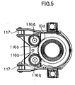
- FIG. 3 is a cross-sectional view taken along lines A-A of FIG. 2.
- a pair of kelly bar guides 115 are formed extending in opposite directions from the lower flange portion 111c of the outer cylindrical part 111a at right angles to a line connecting the two clamping devices 114.
- Similar kelly bar guides 115 are formed on the upper flange portion 111b of the outer cylindrical part 111a as can be seen from FIG. 1.
- each of the kelly bar guides 115 includes a pair of rollers 115a for holding the relevant ridge projection 120a from both sides and a metallic support 115b rotatably supporting the rollers 115a.
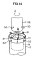
- a pair of metallic fixtures 111f each having a V-shaped groove which can fit onto the upper end 2a of the casing tube 2 are provided on the bottom of two leg projections 111d as shown in FIG. 4.
- a pair of brackets 111b' extending to the left and right as illustrated are formed on the upper flange portion 111b, and rods 112a extending downward from the earlier-mentioned hydraulic cylinders 112 are connected to the brackets 111b'.
- Tubes 112b of the hydraulic cylinders 112 are individually fixed to the movable frame 113.
- a pair of hydraulic motors 116 are installed on the movable frame 113 as shown in FIG. 4.
- driving gears 116b fixed to output shafts 116a of the individual hydraulic motors 116 mesh with an annular gear 10d which is fixed to the outermost cylindrical member 10a of the extensible kelly bar 10, so that the kelly bar 10 can be turned about its vertical axis.
- the numeral 117 indicates pins to which hooks are connected when transporting the ground-boring system 1.
- the extensible kelly bar 10 has a triple telescopic structure in which an intermediate cylindrical member (not shown) and the aforementioned innermost cylindrical member 10c are successively extended from the inside of the outermost cylindrical member 10a as the wire rope 13 is paid out from the crane 12.
- the boring bucket 14 is connected to the lower end of the innermost cylindrical member 10c as stated earlier.
- a coil spring 121, a universal joint 122 and a damper mechanism 123 are provided between the lower end of the innermost cylindrical member 10c and the boring bucket 14, in which the provision of the coil spring 121 is conventional.
- the coil spring 121 absorbs shocks exerted on the boring bucket 14 inside the casing tube 2 during boring operation such that excessive impact load will not be transmitted to motive power sources such as the hydraulic motors 116.
- the universal joint 122 is provided to allow swinging of the boring bucket 14 to thereby ensure smooth boring operation.
- the provision of the damper mechanism 123 is a unique feature of the present embodiment. It absorbs shocks which may occur when the extensible kelly bar 10 is fully contracted as the innermost cylindrical member 10c is retracted into the intermediate cylindrical member and the outermost cylindrical member 10a to prevent damage to the system 1.
- the damper mechanism 123 includes a compression coil spring 123a attached to a stopper plate 124 which collides with the stationary frame 111 when the innermost cylindrical member 10c is fully accommodated into the intermediate cylindrical member and the outermost cylindrical member 10a, such that the compression coil spring 123a absorbs shocks occurring at the end of retraction of the innermost cylindrical member 10c.
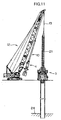
- the casing tube pusher machine 3 is placed at a boring point and the wire rope 13 is paid out from the crane 12 to descend the casing tube 2 into the casing tube pusher machine 3.
- the ground-boring machine 4 suspended by an auxiliary wire rope 13a is kept close to and along a boom 12a of the crane 12 by winding up a pulling wire rope 13b with a winch, such that the crane 12 can be used for ordinary hoisting operation.
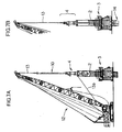
- the ground-boring machine 4 is positioned at the upper end of the casing tube 2 and fixed to the casing tube 2 by the clamping devices 114 as shown in FIG. 7A.
- the boring bucket 14 is set in motion by activating the hydraulic motors 116 of the ground-boring machine 4.
- the wire rope 13 is loosened to lower the boring bucket 14 as shown in FIG. 7B and the hydraulic motors 116 drive the boring bucket 14 to dig the ground within the casing tube 2.
- the ground-boring machine 4 is hauled up as shown in FIG. 8A and its hinged bottom plate 14a is opened to discharge excavated material from the inside of the boring bucket 14.
- the pulling wire rope 13b serves to prevent the ground-boring machine 4 from swinging by centrifugal force when the boring bucket 14 is rotated for discharging the excavated material.
- the casing tube 2 is forced successively deeper into the ground by repeating digging and soil-discharging operations as shown in FIGS. 8B and 9.
- the ground-boring system 1 bores the ground by alternately driving the casing tube 2 into the ground and digging the ground within the casing tube 2 as described above. Since different motive power sources are used for performing the aforementioned casing tube driving and digging operations as shown in the foregoing discussion, work load is not concentrated on the casing tube pusher machine 3 or on the ground-boring machine 4.
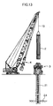
- FIG. 10 is a diagram showing an example in which a hammer grab 20 is used with the ground-boring system 1 of the embodiment due to soil properties at the boring point. Since the present embodiment employs the ordinary crane 12 rather than a dedicated ground-boring machine, the hammer grab 20 may be used to dig a hole and remove excavated material when boring a clayey layer with the ground-boring machine 4 pulled away from the boring point. Thus, the ground-boring system 1 allows the use of the hammer grab 20 or a bedrock-breaking chisel.
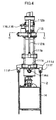
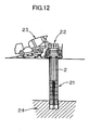
- a tremie pipe 22 is set as shown in FIG. 12 and concrete is poured into the bored hole from a concrete mixer truck 23.
- the numeral 24 indicates an underground bearing stratum.
- boring bucket 14 is used as a boring tool in the foregoing embodiment of the invention, it is possible to use other types of boring tools which are available for making a hole in the ground or for penetrating underground structures. More specifically, it is possible to use such boring tool as a core barrel or a drilling bucket having boring bits embedded in a peripheral end portion of a cylindrical body, such boring tool as a cutter bit or a round bit having cutting media set in a terminal end of a drill, or a boring tool having a widening bit for increasing the diameter of the bottom of a bored hole in a bell-shaped form.
- the boring tool can be moved by winding and unwinding the wire rope 13 of the crane 12 with the ground-boring machine 4 fixed to the upper end 2a of the casing tube 2 so that the boring tool is maintained in a vertical position. It is therefore possible to raise and lower the boring tool at higher speeds inside the casing tube 2. This feature helps increase the efficiency of boring operation compared to leader-type ground-boring machines.
- Another advantageous feature of the ground-boring machine 4 of the embodiment is the ease of installation. Should the ground-boring machine 4 be operated together with the aforementioned boring tools and combined with the all-casing method, it is possible to achieve a high efficiency in carrying out the boring operation.
- hydraulic power for operating the hydraulic motors is supplied from an upper rotating part of the crane 12 in the foregoing embodiment, it may be taken from the casing tube pusher machine 3 according to the invention. Alternatively, there may be provided a separate hydraulic power source for driving the hydraulic motors.
- the reaction force counteracting mechanism of FIG. 14 includes a plurality of arms 30 radially projecting from the outer cylindrical part 111a of the stationary frame 111 in which the kelly bar 10 is inserted and a plurality of arm-locking parts 31 fitted to the upper end of the casing tube 2 at positions corresponding to the arms 30, such that the arms 30 engaged with the arm-locking parts 31 act against a reaction force exerted by the boring bucket 14.
- the arm-locking parts 31 are generally inverted-L-shaped hook metal parts which are fixed to the outer surface of a ring secured to the upper end of the casing tube 2 by bolts 32.
- the casing tube 2 can be fixed to the ground-boring machine 4 by lowering the outer cylindrical part 111a and slightly turning it in the direction of arrow D shown in FIG. 14. It would be understood from the foregoing that the reaction force counteracting mechanism for acting against the reaction force exerted by the boring bucket 14 can be made with an extremely simple construction. In addition, unlike the clamping devices 114, this construction does not require any motive power source or hydraulic cylinders, allowing for a reduction in costs.
- ground-boring machine 4 of the embodiment is preferably used in the all-casing method described above, the invention is not limited thereto.
- the invention is applicable to the earth drill method or reverse circulation drill method, for example.
- the reverse circulation drill method is a method of making a cast-in-place concrete pile, in which a rotary bit is used for boring the ground while protecting the wall of a bored hole with the static pressure of water poured into the bored hole and excavated material is discharged together with return flow of circulating water.
- a rotary bit is used for boring the ground while protecting the wall of a bored hole with the static pressure of water poured into the bored hole and excavated material is discharged together with return flow of circulating water.
- a capping member be fitted to the upper end of the casing tube 2 to prevent its deformation potentially caused when the clamping devices 114 are tightened.
- a capping member can be easily removed without the need of working at height.
- an inventive ground-boring apparatus for boring the ground within a casing tube, which is driven into the ground by a casing tube pusher to prevent the ground from collapsing into a bored hole, and for removing soil from the inside of the bored hole, comprises an extensible telescopic cylinder to be suspended by a movable crane, a boring tool attached to the lower end of the telescopic cylinder, a supporting frame unit to be placed on the casing tube for holding the telescopic cylinder rotatably about its vertical axis, a driver provided on the supporting frame unit for turning the telescopic cylinder about its vertical axis, and an interlock device for joining the supporting frame unit and the casing tube to thereby ensure the rotation of the telescopic cylinder counteracting a reaction force exerted by the rotating telescopic cylinder.
- the above ground-boring apparatus can be placed on the casing tube by suspending the ground-boring apparatus with a movable crane.
- the boring tool attached to the lower end of the telescopic cylinder is turned about its vertical axis by the driver provided on the supporting frame unit, and the casing tube is used to act against the reaction force exerted by the rotating telescopic cylinder via the interlock device during boring operation.
- This construction makes it possible to perform the boring operation without the need of a dedicated ground-boring machine.
- the ground-boring apparatus of the invention makes it possible efficiently bore a hole of a desired diameter regardless of ground conditions of a boring site.
- the ground-boring apparatus suspended by the movable crane can be pulled toward a boom foot by winding up a pulling wire rope, for example, and in this condition, the movable crane can be used to perform such hoisting operation as placing the casing tube into a casing tube pusher machine, or inserting a steel cage into the bored hole. This serves to increase the rate of operation of the crane.
- the boring tool of the ground-boring apparatus may include a boring bucket. This construction makes it possible to efficiently remove the soil from the inside of the casing tube.
- the supporting frame unit may include a stationary frame to be placed on the upper end of the casing tube, a movable frame for holding an outermost cylindrical member of the telescopic cylinder, and a hydraulic cylinder vertically extending from the stationary frame to connect the movable frame to the stationary frame.
- the telescopic cylinder held by the movable frame can be raised and lowered by extending and contracting a rod of the hydraulic cylinder. Therefore, when setting up the ground-boring apparatus by hoisting the telescopic cylinder and moving it to a point above the casing tube using a crane, for example, the ground-boring apparatus already held above the casing tube can be placed down on the casing tube by just extending the rod of the hydraulic cylinder without the need to unwind a wire rope. In addition, once the ground-boring apparatus has been placed on the casing tube and fixed in position, the boring tool can be separated from the ground in a more reliable and safer fashion by contracting the rod of the hydraulic cylinder than lifting the boring tool by winding up the wire rope.
- the interlock device may include a hydraulic clamp for locking the casing tube by clamping its upper end, the hydraulic clamp being movable in a radial direction of the casing tube.
- the hydraulic clamp of the interlock device securely holds the upper end of the casing tube and the casing tube is used to act against a reaction force exerted by the rotating boring tool in this construction, it is possible to increase the torque, or turning force, of the boring tool and the casing tube can be easily fixed to and released from the ground-boring apparatus. Furthermore, since the hydraulic clamp can be moved in the radial direction of the casing tube, the ground-boring apparatus of the present invention is applicable to casing tubes having different diameters.
- the telescopic cylinder may be provided with a shock absorber for damping shocks occurring when the telescopic cylinder is fully contracted.
- An inventive method of boring the ground comprises the steps of driving a casing tube into the ground by a casing tube pusher to prevent the ground from collapsing into a bored hole, placing the aforementioned ground-boring apparatus suspended by a movable crane on the casing tube, fastening the casing tube to the supporting frame unit, and digging the ground within the casing tube while rotating the telescopic cylinder about its vertical axis and extending the telescopic cylinder according to the depth of the bored hole.
- the casing tube to counteract the reaction force exerted by the rotating boring tool when the supporting frame unit of the ground-boring apparatus is fixed to the upper end of the casing tube after driving the casing tube into the ground by the casing tube pusher to prevent the ground from collapsing into the bored hole and placing the ground-boring apparatus on the casing tube.
- the telescopic cylinder is extended while rotating it about its vertical axis by the driver, it is possible to dig the ground within the casing tube.
- the movable frame to be used in the invention may be preferably a crawler crane having a self-propelled chassis and a rotatable upper body on which a tiltable boom is mounted or a wheeled crane or tower crane having an extensible boom, the invention is not limited thereto.
- the movable frame may be a locomotive crane which runs on a railroad.
Landscapes
- Engineering & Computer Science (AREA)
- Structural Engineering (AREA)
- Life Sciences & Earth Sciences (AREA)
- General Life Sciences & Earth Sciences (AREA)
- Mining & Mineral Resources (AREA)
- Paleontology (AREA)
- Civil Engineering (AREA)
- General Engineering & Computer Science (AREA)
- Earth Drilling (AREA)
Applications Claiming Priority (2)
| Application Number | Priority Date | Filing Date | Title |
|---|---|---|---|
| JP2000138897 | 2000-05-11 | ||
| JP2000138897A JP3499504B2 (ja) | 2000-05-11 | 2000-05-11 | 地盤削孔装置及び地盤削孔方法 |
Publications (3)
| Publication Number | Publication Date |
|---|---|
| EP1154078A2 EP1154078A2 (en) | 2001-11-14 |
| EP1154078A3 EP1154078A3 (en) | 2003-03-19 |
| EP1154078B1 true EP1154078B1 (en) | 2005-10-05 |
Family
ID=18646441
Family Applications (1)
| Application Number | Title | Priority Date | Filing Date |
|---|---|---|---|
| EP01110402A Expired - Lifetime EP1154078B1 (en) | 2000-05-11 | 2001-04-27 | Apparatus for and a method of boring the ground |
Country Status (7)
| Country | Link |
|---|---|
| US (1) | US6540443B2 (ja) |
| EP (1) | EP1154078B1 (ja) |
| JP (1) | JP3499504B2 (ja) |
| AT (1) | ATE305995T1 (ja) |
| DE (1) | DE60113763T2 (ja) |
| DK (1) | DK1154078T3 (ja) |
| HK (1) | HK1040750B (ja) |
Cited By (2)
| Publication number | Priority date | Publication date | Assignee | Title |
|---|---|---|---|---|
| JP2011047269A (ja) * | 2009-08-28 | 2011-03-10 | Bauer Maschinen Gmbh | 掘削機および掘削方法 |
| EP3363987A1 (de) | 2017-02-20 | 2018-08-22 | BAUER Maschinen GmbH | Bohrvorrichtung und bohrverfahren zum erstellen einer bohrung |
Families Citing this family (27)
| Publication number | Priority date | Publication date | Assignee | Title |
|---|---|---|---|---|
| US8152415B2 (en) * | 2000-06-15 | 2012-04-10 | Geopier Foundation Company, Inc. | Method and apparatus for building support piers from one or more successive lifts formed in a soil matrix |
| US7226246B2 (en) * | 2000-06-15 | 2007-06-05 | Geotechnical Reinforcement, Inc. | Apparatus and method for building support piers from one or successive lifts formed in a soil matrix |
| KR100437445B1 (ko) * | 2001-11-13 | 2004-06-30 | 강경식 | 대구경 지반굴착기 |
| DE502004007220D1 (de) * | 2004-03-19 | 2008-07-03 | Bauer Maschinen Gmbh | Kranwinde |
| US20080131211A1 (en) * | 2004-07-13 | 2008-06-05 | Nesmith Willie M | Installation effort deep foudnation method |
| US7198434B2 (en) * | 2004-07-13 | 2007-04-03 | Berkel & Company Contractors, Inc. | Full-displacement pressure grouted pile system and method |
| US20060051162A1 (en) * | 2004-09-07 | 2006-03-09 | Warren Chesner | Rotating containment tool for contaminated sediment remediation in an aqueous environment |
| WO2008111032A1 (en) * | 2007-03-15 | 2008-09-18 | Lilianto Ong Poi Nguan | Method of preparing a hole for a post pile cast in place using hydraulic pressure and apparatus therefor |
| JP5380142B2 (ja) * | 2009-04-22 | 2014-01-08 | システム計測株式会社 | 拡底バケット、ケーシング、及び拡底杭の構築方法 |
| US8375551B2 (en) * | 2009-09-29 | 2013-02-19 | Argonics, Inc. | Method for covering an above ground access opening to a conduit assembly |
| EP2576130B1 (en) | 2010-05-28 | 2018-12-19 | Brasfond USA Corp. | A pipeline insertion system |
| DK2407629T3 (da) * | 2010-07-16 | 2013-01-21 | Bauer Maschinen Gmbh | Boreindretning og borefremgangsmåde |
| US8425157B1 (en) * | 2012-02-28 | 2013-04-23 | American Piledriving Equipment, Inc. | Clamp for pile driving |
| JP5380574B2 (ja) * | 2012-04-25 | 2014-01-08 | システム計測株式会社 | バケット、ケーシング、及び杭の構築方法 |
| JP6105892B2 (ja) * | 2012-10-15 | 2017-03-29 | 豊栄産業株式会社 | 掘削装置 |
| JP6144569B2 (ja) * | 2013-07-31 | 2017-06-07 | 日本車輌製造株式会社 | 動力伝達装置 |
| JP6210825B2 (ja) * | 2013-10-03 | 2017-10-11 | 日本車輌製造株式会社 | 動力伝達装置 |
| JP6250410B2 (ja) * | 2014-01-22 | 2017-12-20 | 日本車輌製造株式会社 | 動力伝達装置 |
| CN105089536B (zh) * | 2015-08-07 | 2017-07-18 | 武汉卡特工业股份有限公司 | 一种用于旋挖钻机的钻杆救援装置 |
| CN105926594A (zh) * | 2016-04-29 | 2016-09-07 | 朱龙 | 一种静压沉管载体灌注桩的双管施工方法 |
| CN105887812B (zh) * | 2016-04-29 | 2017-07-28 | 朱龙 | 一种静压沉管载体灌注桩的单护筒施工方法 |
| CN112554176B (zh) * | 2020-11-23 | 2022-04-26 | 四川路航建设工程有限责任公司 | 全护筒拧管跟进旋挖成孔施工方法 |
| CN113482368B (zh) * | 2021-06-25 | 2022-07-26 | 中建一局集团第五建筑有限公司 | 一种吊杆打孔安装一体机及其施工方法 |
| CN113356754A (zh) * | 2021-07-15 | 2021-09-07 | 张国 | 一种顶驱式全套管潜孔钻具 |
| CN113565094A (zh) * | 2021-07-19 | 2021-10-29 | 杨菊芳 | 一种农业大棚搭建用的辅助设备 |
| CN115506350A (zh) * | 2022-10-12 | 2022-12-23 | 杭州余杭建筑设计院有限公司 | 一种既有桩基清障的施工装置及其施工方法 |
| CN115652964B (zh) * | 2022-12-07 | 2023-06-02 | 福建省地质工程勘察院 | 一种卵石层湿法钻进施工工艺及设备 |
Family Cites Families (5)
| Publication number | Priority date | Publication date | Assignee | Title |
|---|---|---|---|---|
| US4202416A (en) * | 1978-08-07 | 1980-05-13 | Stahl- Und Apparatebau Hans Leffer Gmbh | Method and apparatus for sinking a cased borehole for producing cased pile foundations |
| JPS6168924A (ja) * | 1984-09-10 | 1986-04-09 | Tokai Concrete Kogyo Kk | くいの埋込工法 |
| JPS6319328A (ja) * | 1986-07-11 | 1988-01-27 | Nisshin Kiso Kogyo Kk | 回転圧入式大口径鋼管類建込み工法およびその装置 |
| JP3452084B2 (ja) * | 1994-05-18 | 2003-09-29 | 日本基礎技術株式会社 | 掘削装置 |
| US5653556A (en) * | 1995-10-10 | 1997-08-05 | American Piledriving Equipment, Inc. | Clamping apparatus and methods for driving caissons into the earth |
-
2000
- 2000-05-11 JP JP2000138897A patent/JP3499504B2/ja not_active Expired - Lifetime
-
2001
- 2001-04-27 DK DK01110402T patent/DK1154078T3/da active
- 2001-04-27 AT AT01110402T patent/ATE305995T1/de active
- 2001-04-27 EP EP01110402A patent/EP1154078B1/en not_active Expired - Lifetime
- 2001-04-27 DE DE60113763T patent/DE60113763T2/de not_active Expired - Lifetime
- 2001-05-10 US US09/852,219 patent/US6540443B2/en not_active Expired - Lifetime
-
2002
- 2002-04-04 HK HK02102550.6A patent/HK1040750B/zh not_active IP Right Cessation
Cited By (3)
| Publication number | Priority date | Publication date | Assignee | Title |
|---|---|---|---|---|
| JP2011047269A (ja) * | 2009-08-28 | 2011-03-10 | Bauer Maschinen Gmbh | 掘削機および掘削方法 |
| EP2295646A1 (de) | 2009-08-28 | 2011-03-16 | BAUER Maschinen GmbH | Bohrvorrichtung und Bohrverfahren |
| EP3363987A1 (de) | 2017-02-20 | 2018-08-22 | BAUER Maschinen GmbH | Bohrvorrichtung und bohrverfahren zum erstellen einer bohrung |
Also Published As
| Publication number | Publication date |
|---|---|
| DK1154078T3 (da) | 2006-02-06 |
| DE60113763D1 (de) | 2006-02-16 |
| ATE305995T1 (de) | 2005-10-15 |
| DE60113763T2 (de) | 2006-06-22 |
| US20010041099A1 (en) | 2001-11-15 |
| HK1040750B (zh) | 2006-02-17 |
| EP1154078A2 (en) | 2001-11-14 |
| EP1154078A3 (en) | 2003-03-19 |
| JP2001317282A (ja) | 2001-11-16 |
| US6540443B2 (en) | 2003-04-01 |
| JP3499504B2 (ja) | 2004-02-23 |
| HK1040750A1 (en) | 2002-06-21 |
Similar Documents
| Publication | Publication Date | Title |
|---|---|---|
| EP1154078B1 (en) | Apparatus for and a method of boring the ground | |
| US4202416A (en) | Method and apparatus for sinking a cased borehole for producing cased pile foundations | |
| JP6081100B2 (ja) | 既設杭引き抜き装置 | |
| JPS6319328A (ja) | 回転圧入式大口径鋼管類建込み工法およびその装置 | |
| EP2102419A2 (en) | Drill head for the excavation in the ground of a pit, and a foundation system for the forming of a foundation pile in the ground | |
| JP2007291807A (ja) | 基礎機械および軸体の着脱方法 | |
| KR100479514B1 (ko) | 굴착 장치 및 방법 | |
| JP3978469B2 (ja) | 拡開掘削装置および杭底拡大工法 | |
| JP3648289B2 (ja) | 硬岩層掘削方法及びその装置 | |
| JP3451275B2 (ja) | 深礎掘削機 | |
| JP2007218039A (ja) | 既設杭撤去方法及びその装置 | |
| JP3839819B2 (ja) | リバースサーキュレーションドリル | |
| JP4920352B2 (ja) | 掘削装置 | |
| JP4399436B2 (ja) | 掘削揚土用バケットとそのバケットを用いた掘削揚土装置 | |
| CN113323053B (zh) | 旋管压挖桩机 | |
| CN220301420U (zh) | 旋管压挖桩机 | |
| JP3037609B2 (ja) | 掘削装置 | |
| JP2007009671A (ja) | 既設杭の撤去装置および既設杭の撤去工法 | |
| JP4755361B2 (ja) | 立坑構築工法 | |
| JP2005314871A (ja) | 地中障害物の除去装置、および地中障害物の除去方法 | |
| JP2930861B2 (ja) | 孔掘削工法及び孔掘削装置 | |
| JPS6146608B2 (ja) | ||
| JP3396025B2 (ja) | 立型掘進工法及びその装置 | |
| JPH0366828A (ja) | オーガーまたは杭と、穿孔または杭打装置、及び穿孔または杭打法 | |
| JP2018178456A (ja) | 地中障害物除去方法 |
Legal Events
| Date | Code | Title | Description |
|---|---|---|---|
| PUAI | Public reference made under article 153(3) epc to a published international application that has entered the european phase |
Free format text: ORIGINAL CODE: 0009012 |
|
| AK | Designated contracting states |
Kind code of ref document: A2 Designated state(s): AT BE CH CY DE DK ES FI FR GB GR IE IT LI LU MC NL PT SE TR |
|
| AX | Request for extension of the european patent |
Free format text: AL;LT;LV;MK;RO;SI |
|
| RAP1 | Party data changed (applicant data changed or rights of an application transferred) |
Owner name: BAUER MASCHINEN GMBH Owner name: KATO KENKI YUGEN KAISHA |
|
| PUAL | Search report despatched |
Free format text: ORIGINAL CODE: 0009013 |
|
| AK | Designated contracting states |
Kind code of ref document: A3 Designated state(s): AT BE CH CY DE DK ES FI FR GB GR IE IT LI LU MC NL PT SE TR |
|
| AX | Request for extension of the european patent |
Extension state: AL LT LV MK RO SI |
|
| RIC1 | Information provided on ipc code assigned before grant |
Ipc: 7E 02D 7/20 A Ipc: 7E 02D 5/38 B |
|
| 17P | Request for examination filed |
Effective date: 20030317 |
|
| AKX | Designation fees paid |
Designated state(s): AT BE CH CY DE DK ES FI FR GB GR IE IT LI LU MC NL PT SE TR |
|
| AXX | Extension fees paid |
Extension state: SI Payment date: 20030317 |
|
| 17Q | First examination report despatched |
Effective date: 20040514 |
|
| GRAP | Despatch of communication of intention to grant a patent |
Free format text: ORIGINAL CODE: EPIDOSNIGR1 |
|
| GRAS | Grant fee paid |
Free format text: ORIGINAL CODE: EPIDOSNIGR3 |
|
| GRAA | (expected) grant |
Free format text: ORIGINAL CODE: 0009210 |
|
| AK | Designated contracting states |
Kind code of ref document: B1 Designated state(s): AT BE CH CY DE DK ES FI FR GB GR IE IT LI LU MC NL PT SE TR |
|
| AX | Request for extension of the european patent |
Extension state: SI |
|
| PG25 | Lapsed in a contracting state [announced via postgrant information from national office to epo] |
Ref country code: FI Free format text: LAPSE BECAUSE OF FAILURE TO SUBMIT A TRANSLATION OF THE DESCRIPTION OR TO PAY THE FEE WITHIN THE PRESCRIBED TIME-LIMIT Effective date: 20051005 |
|
| REG | Reference to a national code |
Ref country code: GB Ref legal event code: FG4D |
|
| REG | Reference to a national code |
Ref country code: CH Ref legal event code: EP |
|
| REG | Reference to a national code |
Ref country code: IE Ref legal event code: FG4D |
|
| REG | Reference to a national code |
Ref country code: CH Ref legal event code: NV Representative=s name: SCHMAUDER & PARTNER AG PATENTANWALTSBUERO |
|
| PG25 | Lapsed in a contracting state [announced via postgrant information from national office to epo] |
Ref country code: GR Free format text: LAPSE BECAUSE OF FAILURE TO SUBMIT A TRANSLATION OF THE DESCRIPTION OR TO PAY THE FEE WITHIN THE PRESCRIBED TIME-LIMIT Effective date: 20060105 |
|
| REG | Reference to a national code |
Ref country code: SE Ref legal event code: TRGR |
|
| PG25 | Lapsed in a contracting state [announced via postgrant information from national office to epo] |
Ref country code: ES Free format text: LAPSE BECAUSE OF FAILURE TO SUBMIT A TRANSLATION OF THE DESCRIPTION OR TO PAY THE FEE WITHIN THE PRESCRIBED TIME-LIMIT Effective date: 20060116 |
|
| REG | Reference to a national code |
Ref country code: DK Ref legal event code: T3 |
|
| REF | Corresponds to: |
Ref document number: 60113763 Country of ref document: DE Date of ref document: 20060216 Kind code of ref document: P |
|
| REG | Reference to a national code |
Ref country code: HK Ref legal event code: GR Ref document number: 1040750 Country of ref document: HK |
|
| PG25 | Lapsed in a contracting state [announced via postgrant information from national office to epo] |
Ref country code: PT Free format text: LAPSE BECAUSE OF FAILURE TO SUBMIT A TRANSLATION OF THE DESCRIPTION OR TO PAY THE FEE WITHIN THE PRESCRIBED TIME-LIMIT Effective date: 20060306 |
|
| PG25 | Lapsed in a contracting state [announced via postgrant information from national office to epo] |
Ref country code: MC Free format text: LAPSE BECAUSE OF NON-PAYMENT OF DUE FEES Effective date: 20060430 |
|
| ET | Fr: translation filed | ||
| PLBE | No opposition filed within time limit |
Free format text: ORIGINAL CODE: 0009261 |
|
| STAA | Information on the status of an ep patent application or granted ep patent |
Free format text: STATUS: NO OPPOSITION FILED WITHIN TIME LIMIT |
|
| 26N | No opposition filed |
Effective date: 20060706 |
|
| PG25 | Lapsed in a contracting state [announced via postgrant information from national office to epo] |
Ref country code: TR Free format text: LAPSE BECAUSE OF FAILURE TO SUBMIT A TRANSLATION OF THE DESCRIPTION OR TO PAY THE FEE WITHIN THE PRESCRIBED TIME-LIMIT Effective date: 20051005 Ref country code: LU Free format text: LAPSE BECAUSE OF NON-PAYMENT OF DUE FEES Effective date: 20060427 |
|
| PG25 | Lapsed in a contracting state [announced via postgrant information from national office to epo] |
Ref country code: CY Free format text: LAPSE BECAUSE OF FAILURE TO SUBMIT A TRANSLATION OF THE DESCRIPTION OR TO PAY THE FEE WITHIN THE PRESCRIBED TIME-LIMIT Effective date: 20051005 |
|
| REG | Reference to a national code |
Ref country code: CH Ref legal event code: PCAR Free format text: SCHMAUDER & PARTNER AG PATENT- UND MARKENANWAELTE VSP;ZWAENGIWEG 7;8038 ZUERICH (CH) |
|
| PGFP | Annual fee paid to national office [announced via postgrant information from national office to epo] |
Ref country code: SE Payment date: 20090424 Year of fee payment: 9 |
|
| PGFP | Annual fee paid to national office [announced via postgrant information from national office to epo] |
Ref country code: CH Payment date: 20090421 Year of fee payment: 9 |
|
| EUG | Se: european patent has lapsed | ||
| REG | Reference to a national code |
Ref country code: CH Ref legal event code: PL |
|
| PG25 | Lapsed in a contracting state [announced via postgrant information from national office to epo] |
Ref country code: CH Free format text: LAPSE BECAUSE OF NON-PAYMENT OF DUE FEES Effective date: 20100430 Ref country code: LI Free format text: LAPSE BECAUSE OF NON-PAYMENT OF DUE FEES Effective date: 20100430 |
|
| PG25 | Lapsed in a contracting state [announced via postgrant information from national office to epo] |
Ref country code: SE Free format text: LAPSE BECAUSE OF NON-PAYMENT OF DUE FEES Effective date: 20100428 |
|
| PGFP | Annual fee paid to national office [announced via postgrant information from national office to epo] |
Ref country code: AT Payment date: 20120425 Year of fee payment: 12 |
|
| PGFP | Annual fee paid to national office [announced via postgrant information from national office to epo] |
Ref country code: DK Payment date: 20130429 Year of fee payment: 13 Ref country code: IE Payment date: 20130412 Year of fee payment: 13 |
|
| PGFP | Annual fee paid to national office [announced via postgrant information from national office to epo] |
Ref country code: BE Payment date: 20130515 Year of fee payment: 13 Ref country code: NL Payment date: 20130426 Year of fee payment: 13 |
|
| REG | Reference to a national code |
Ref country code: DK Ref legal event code: EBP Effective date: 20140430 |
|
| REG | Reference to a national code |
Ref country code: NL Ref legal event code: V1 Effective date: 20141101 |
|
| REG | Reference to a national code |
Ref country code: AT Ref legal event code: MM01 Ref document number: 305995 Country of ref document: AT Kind code of ref document: T Effective date: 20140427 |
|
| REG | Reference to a national code |
Ref country code: IE Ref legal event code: MM4A |
|
| PG25 | Lapsed in a contracting state [announced via postgrant information from national office to epo] |
Ref country code: AT Free format text: LAPSE BECAUSE OF NON-PAYMENT OF DUE FEES Effective date: 20140427 Ref country code: NL Free format text: LAPSE BECAUSE OF NON-PAYMENT OF DUE FEES Effective date: 20141101 |
|
| PG25 | Lapsed in a contracting state [announced via postgrant information from national office to epo] |
Ref country code: DK Free format text: LAPSE BECAUSE OF NON-PAYMENT OF DUE FEES Effective date: 20140430 Ref country code: IE Free format text: LAPSE BECAUSE OF NON-PAYMENT OF DUE FEES Effective date: 20140427 |
|
| REG | Reference to a national code |
Ref country code: FR Ref legal event code: PLFP Year of fee payment: 16 |
|
| REG | Reference to a national code |
Ref country code: FR Ref legal event code: PLFP Year of fee payment: 17 |
|
| PG25 | Lapsed in a contracting state [announced via postgrant information from national office to epo] |
Ref country code: BE Free format text: LAPSE BECAUSE OF NON-PAYMENT OF DUE FEES Effective date: 20140430 |
|
| REG | Reference to a national code |
Ref country code: FR Ref legal event code: PLFP Year of fee payment: 18 |
|
| REG | Reference to a national code |
Ref country code: DE Ref legal event code: R082 Ref document number: 60113763 Country of ref document: DE Representative=s name: WUNDERLICH & HEIM PATENTANWAELTE PARTNERSCHAFT, DE |
|
| PGFP | Annual fee paid to national office [announced via postgrant information from national office to epo] |
Ref country code: DE Payment date: 20200428 Year of fee payment: 20 Ref country code: FR Payment date: 20200421 Year of fee payment: 20 |
|
| PGFP | Annual fee paid to national office [announced via postgrant information from national office to epo] |
Ref country code: IT Payment date: 20200423 Year of fee payment: 20 Ref country code: GB Payment date: 20200423 Year of fee payment: 20 |
|
| REG | Reference to a national code |
Ref country code: DE Ref legal event code: R071 Ref document number: 60113763 Country of ref document: DE |
|
| REG | Reference to a national code |
Ref country code: GB Ref legal event code: PE20 Expiry date: 20210426 |
|
| PG25 | Lapsed in a contracting state [announced via postgrant information from national office to epo] |
Ref country code: GB Free format text: LAPSE BECAUSE OF EXPIRATION OF PROTECTION Effective date: 20210426 |