EP1152182B1 - Support avec un microscope chirurgical - Google Patents
Support avec un microscope chirurgical Download PDFInfo
- Publication number
- EP1152182B1 EP1152182B1 EP00108786A EP00108786A EP1152182B1 EP 1152182 B1 EP1152182 B1 EP 1152182B1 EP 00108786 A EP00108786 A EP 00108786A EP 00108786 A EP00108786 A EP 00108786A EP 1152182 B1 EP1152182 B1 EP 1152182B1
- Authority
- EP
- European Patent Office
- Prior art keywords
- microscope
- stand according
- sensors
- stand
- axis
- Prior art date
- Legal status (The legal status is an assumption and is not a legal conclusion. Google has not performed a legal analysis and makes no representation as to the accuracy of the status listed.)
- Expired - Lifetime
Links
- 230000003287 optical effect Effects 0.000 claims abstract description 7
- 238000006073 displacement reaction Methods 0.000 claims description 3
- 230000001939 inductive effect Effects 0.000 claims description 2
- 230000004913 activation Effects 0.000 claims 1
- 230000007246 mechanism Effects 0.000 claims 1
- 230000000694 effects Effects 0.000 description 5
- 230000005484 gravity Effects 0.000 description 5
- 230000007935 neutral effect Effects 0.000 description 3
- 238000001356 surgical procedure Methods 0.000 description 3
- 239000000725 suspension Substances 0.000 description 3
- 230000008859 change Effects 0.000 description 2
- 230000008901 benefit Effects 0.000 description 1
- 230000005540 biological transmission Effects 0.000 description 1
- 210000004556 brain Anatomy 0.000 description 1
- 238000005516 engineering process Methods 0.000 description 1
- 238000011156 evaluation Methods 0.000 description 1
- 230000002349 favourable effect Effects 0.000 description 1
- 238000000034 method Methods 0.000 description 1
- 230000008569 process Effects 0.000 description 1
- 230000004044 response Effects 0.000 description 1
- 230000000630 rising effect Effects 0.000 description 1
- 210000000278 spinal cord Anatomy 0.000 description 1
- 230000001360 synchronised effect Effects 0.000 description 1
Images

Classifications
-
- F—MECHANICAL ENGINEERING; LIGHTING; HEATING; WEAPONS; BLASTING
- F16—ENGINEERING ELEMENTS AND UNITS; GENERAL MEASURES FOR PRODUCING AND MAINTAINING EFFECTIVE FUNCTIONING OF MACHINES OR INSTALLATIONS; THERMAL INSULATION IN GENERAL
- F16M—FRAMES, CASINGS OR BEDS OF ENGINES, MACHINES OR APPARATUS, NOT SPECIFIC TO ENGINES, MACHINES OR APPARATUS PROVIDED FOR ELSEWHERE; STANDS; SUPPORTS
- F16M11/00—Stands or trestles as supports for apparatus or articles placed thereon ; Stands for scientific apparatus such as gravitational force meters
- F16M11/42—Stands or trestles as supports for apparatus or articles placed thereon ; Stands for scientific apparatus such as gravitational force meters with arrangement for propelling the support stands on wheels
-
- A—HUMAN NECESSITIES
- A61—MEDICAL OR VETERINARY SCIENCE; HYGIENE
- A61B—DIAGNOSIS; SURGERY; IDENTIFICATION
- A61B90/00—Instruments, implements or accessories specially adapted for surgery or diagnosis and not covered by any of the groups A61B1/00 - A61B50/00, e.g. for luxation treatment or for protecting wound edges
- A61B90/20—Surgical microscopes characterised by non-optical aspects
- A61B90/25—Supports therefor
-
- A—HUMAN NECESSITIES
- A61—MEDICAL OR VETERINARY SCIENCE; HYGIENE
- A61B—DIAGNOSIS; SURGERY; IDENTIFICATION
- A61B90/00—Instruments, implements or accessories specially adapted for surgery or diagnosis and not covered by any of the groups A61B1/00 - A61B50/00, e.g. for luxation treatment or for protecting wound edges
- A61B90/50—Supports for surgical instruments, e.g. articulated arms
-
- F—MECHANICAL ENGINEERING; LIGHTING; HEATING; WEAPONS; BLASTING
- F16—ENGINEERING ELEMENTS AND UNITS; GENERAL MEASURES FOR PRODUCING AND MAINTAINING EFFECTIVE FUNCTIONING OF MACHINES OR INSTALLATIONS; THERMAL INSULATION IN GENERAL
- F16M—FRAMES, CASINGS OR BEDS OF ENGINES, MACHINES OR APPARATUS, NOT SPECIFIC TO ENGINES, MACHINES OR APPARATUS PROVIDED FOR ELSEWHERE; STANDS; SUPPORTS
- F16M11/00—Stands or trestles as supports for apparatus or articles placed thereon ; Stands for scientific apparatus such as gravitational force meters
- F16M11/02—Heads
- F16M11/18—Heads with mechanism for moving the apparatus relatively to the stand
-
- F—MECHANICAL ENGINEERING; LIGHTING; HEATING; WEAPONS; BLASTING
- F16—ENGINEERING ELEMENTS AND UNITS; GENERAL MEASURES FOR PRODUCING AND MAINTAINING EFFECTIVE FUNCTIONING OF MACHINES OR INSTALLATIONS; THERMAL INSULATION IN GENERAL
- F16M—FRAMES, CASINGS OR BEDS OF ENGINES, MACHINES OR APPARATUS, NOT SPECIFIC TO ENGINES, MACHINES OR APPARATUS PROVIDED FOR ELSEWHERE; STANDS; SUPPORTS
- F16M11/00—Stands or trestles as supports for apparatus or articles placed thereon ; Stands for scientific apparatus such as gravitational force meters
- F16M11/20—Undercarriages with or without wheels
- F16M11/2007—Undercarriages with or without wheels comprising means allowing pivoting adjustment
- F16M11/2014—Undercarriages with or without wheels comprising means allowing pivoting adjustment around a vertical axis
-
- F—MECHANICAL ENGINEERING; LIGHTING; HEATING; WEAPONS; BLASTING
- F16—ENGINEERING ELEMENTS AND UNITS; GENERAL MEASURES FOR PRODUCING AND MAINTAINING EFFECTIVE FUNCTIONING OF MACHINES OR INSTALLATIONS; THERMAL INSULATION IN GENERAL
- F16M—FRAMES, CASINGS OR BEDS OF ENGINES, MACHINES OR APPARATUS, NOT SPECIFIC TO ENGINES, MACHINES OR APPARATUS PROVIDED FOR ELSEWHERE; STANDS; SUPPORTS
- F16M11/00—Stands or trestles as supports for apparatus or articles placed thereon ; Stands for scientific apparatus such as gravitational force meters
- F16M11/20—Undercarriages with or without wheels
- F16M11/2092—Undercarriages with or without wheels comprising means allowing depth adjustment, i.e. forward-backward translation of the head relatively to the undercarriage
-
- F—MECHANICAL ENGINEERING; LIGHTING; HEATING; WEAPONS; BLASTING
- F16—ENGINEERING ELEMENTS AND UNITS; GENERAL MEASURES FOR PRODUCING AND MAINTAINING EFFECTIVE FUNCTIONING OF MACHINES OR INSTALLATIONS; THERMAL INSULATION IN GENERAL
- F16M—FRAMES, CASINGS OR BEDS OF ENGINES, MACHINES OR APPARATUS, NOT SPECIFIC TO ENGINES, MACHINES OR APPARATUS PROVIDED FOR ELSEWHERE; STANDS; SUPPORTS
- F16M11/00—Stands or trestles as supports for apparatus or articles placed thereon ; Stands for scientific apparatus such as gravitational force meters
- F16M11/20—Undercarriages with or without wheels
- F16M11/24—Undercarriages with or without wheels changeable in height or length of legs, also for transport only, e.g. by means of tubes screwed into each other
-
- G—PHYSICS
- G02—OPTICS
- G02B—OPTICAL ELEMENTS, SYSTEMS OR APPARATUS
- G02B7/00—Mountings, adjusting means, or light-tight connections, for optical elements
- G02B7/001—Counterbalanced structures, e.g. surgical microscopes
-
- A—HUMAN NECESSITIES
- A61—MEDICAL OR VETERINARY SCIENCE; HYGIENE
- A61B—DIAGNOSIS; SURGERY; IDENTIFICATION
- A61B90/00—Instruments, implements or accessories specially adapted for surgery or diagnosis and not covered by any of the groups A61B1/00 - A61B50/00, e.g. for luxation treatment or for protecting wound edges
- A61B90/50—Supports for surgical instruments, e.g. articulated arms
- A61B2090/502—Headgear, e.g. helmet, spectacles
-
- A—HUMAN NECESSITIES
- A61—MEDICAL OR VETERINARY SCIENCE; HYGIENE
- A61B—DIAGNOSIS; SURGERY; IDENTIFICATION
- A61B90/00—Instruments, implements or accessories specially adapted for surgery or diagnosis and not covered by any of the groups A61B1/00 - A61B50/00, e.g. for luxation treatment or for protecting wound edges
- A61B90/50—Supports for surgical instruments, e.g. articulated arms
- A61B2090/506—Supports for surgical instruments, e.g. articulated arms using a parallelogram linkage, e.g. panthograph
-
- A—HUMAN NECESSITIES
- A61—MEDICAL OR VETERINARY SCIENCE; HYGIENE
- A61B—DIAGNOSIS; SURGERY; IDENTIFICATION
- A61B90/00—Instruments, implements or accessories specially adapted for surgery or diagnosis and not covered by any of the groups A61B1/00 - A61B50/00, e.g. for luxation treatment or for protecting wound edges
- A61B90/20—Surgical microscopes characterised by non-optical aspects
-
- F—MECHANICAL ENGINEERING; LIGHTING; HEATING; WEAPONS; BLASTING
- F16—ENGINEERING ELEMENTS AND UNITS; GENERAL MEASURES FOR PRODUCING AND MAINTAINING EFFECTIVE FUNCTIONING OF MACHINES OR INSTALLATIONS; THERMAL INSULATION IN GENERAL
- F16M—FRAMES, CASINGS OR BEDS OF ENGINES, MACHINES OR APPARATUS, NOT SPECIFIC TO ENGINES, MACHINES OR APPARATUS PROVIDED FOR ELSEWHERE; STANDS; SUPPORTS
- F16M2200/00—Details of stands or supports
- F16M2200/04—Balancing means
- F16M2200/044—Balancing means for balancing rotational movement of the undercarriage
-
- F—MECHANICAL ENGINEERING; LIGHTING; HEATING; WEAPONS; BLASTING
- F16—ENGINEERING ELEMENTS AND UNITS; GENERAL MEASURES FOR PRODUCING AND MAINTAINING EFFECTIVE FUNCTIONING OF MACHINES OR INSTALLATIONS; THERMAL INSULATION IN GENERAL
- F16M—FRAMES, CASINGS OR BEDS OF ENGINES, MACHINES OR APPARATUS, NOT SPECIFIC TO ENGINES, MACHINES OR APPARATUS PROVIDED FOR ELSEWHERE; STANDS; SUPPORTS
- F16M2200/00—Details of stands or supports
- F16M2200/06—Arms
- F16M2200/063—Parallelogram arms
Definitions
- the invention relates to a surgical microscope with a tripod, wherein the microscope has a total of up to six degrees of freedom and is attached via elements of the tripod to the microscope suspension, wherein the stand two vertical pivot axes, which are not subject to influence by gravity, and for the height adjustment a parallelogram linkage having weight compensation, which are designed with smooth movement and with brakes for locking.
- the microscope can be brought by means of the tripod in the position desired for the operation. It has a counterbalance, so that it remains in this position even with weakly braked joints. But it is very expensive to effect this weight balance. Subsequent adjustment of the microscope to change the image field must be done by hand.
- the axes are moved by motor actuation of an operating handle.
- the object of the invention is to provide a microscope with a tripod, in which the adjustment of the location of the microscope can be done quickly by hand, but then a fine adjustment of the observable image field can be made without this handling by gravitational forces or moments caused thereby is disturbed.
- the solution according to the invention consists in that the microscope is mounted on the stand via a third vertical axis, which is not subjected to any influence by gravity, a first axis perpendicular thereto and a second further to the first further vertical axis to the first, wherein the other axes in are formed substantially perpendicular to the optical axis of the microscope objective and motor adjustable and closer to the microscope further axis a lateral Pivoting the viewing direction (X-direction) allows and arranged between the third vertical axis and the microscope closer to another axis further axis pivoting the viewing direction forward / backward or up / down (Y-direction) allows.
- the invention is not exhausted in that the movement about these axes can be made quickly by hand and then the axes can be blocked in this position. Rather, the invention is characterized by a combination of this adjustment by hand with a motor setting.
- the larger adjustment of the tripod are the user / surgeon in a conventional manner weight balanced in the so-called "free floating mode" released. He leads the device to a handle, for example, with an integrated button, with the movement can be released.
- a fine weight balance has been made on Parallelogrammarm. This total weight balance must be as accurate as possible, so that only very small forces are required for the settings.
- An imbalance in the two existing directly on the microscope adjustment axes does not interfere if these axes, a motor adjustment is provided and the motors are powerful enough to absorb the corresponding forces of imbalance.
- the surgeon can adapt the field of view to the requirements.
- the other two axes is given a very convenient adjustability for different operating conditions. Namely, the optical axis of the surgical microscope is used for different operations (eg brain surgery, Spinal cord surgery, eye surgery) completely different to the vertical aligned. If one chooses the order of the other axis differently, then this favorable change of the field of vision is no longer possible.
- the motor drives are designed as servo drives.
- the default for these servo functions is preferably done by electrical force or torque sensors between the microscope and the control element for the respective directions.
- the sensors are designed to emit a signal rising from the user with the torque exerted on the control element about an axis and changing sign when the direction changes.
- the controls are adjustable so that the user can adjust them to the most comfortable position for him, without causing the position of the sensors to the microscope and thus the relationship between the signals and effective direction is changed.
- the sensors are arranged in pairs so that when a force exerted by an operator on the control element relieves one sensor, the other is loaded. Both sensors are arranged on both sides of a neutral line with respect to the torque to be detected or the force to be detected. Both sensor elements are under pressure and are connected in a bridge circuit against each other, so that the signals cancel each other by the pressure. If a moment or force is introduced into the control element which attempts to effect a rotation about this line, pressure will increase on one side of the neutral line and falling pressure on the other side. Accordingly, the bridge is detuned and provides an instantaneous output signal. Piezo elements, inductive sensors, capacitive sensors, resistive and optical force / displacement sensors can be used as sensors.
- the signals are processed further in terms of control technology in order to make the adjustments via motor drivers and servomotors.
- the response times are reduced. While the user adjusts the microscope in the four degrees of freedom released for movement, at the same time the moments introduced for the direction adjustment of the microscope axis act on the operating element and effect the corresponding adjustment with the servo controls. Due to the synchronous free adjustment of the microscope with larger paths and the servo tracking of the small rotational movements eliminates the well-known from pure servo systems effect that the user must wait long until the adjustment is completed.
- the arrangement is such that the possible movements about the individual axes or degrees of freedom are limited so that the microscope can not abut against parts of the tripod.
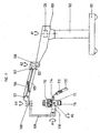
- Fig. 1 the arrangement of a surgical microscope is shown on a floor stand.
- the stand stands on a base or foot 101, which is generally equipped with rollers for the process.
- the base part 101 may also be designed for ceiling or wall mounting.
- a column 102 is mounted, about whose axis A1, the patch fixed arm 103 can rotate.
- a parallelogram arm 105 with axle 107 is attached thereto by a joint which is rotatable about the axis A2.
- the height adjustment of the microscope port 108 on the parallelogram 105 is weight balanced with a gas spring or a spring package 106.
- the microscope consists of a microscope body 111, the view 112 and the lens 116 and is rotatably mounted with the arms 110 and 109 about the axis A3 on the microscope port of the tripod. It can be with the rotations about the axes A1, A2 and A3 and by the weight-balanced height adjustment with the Parallelogrammarm 105 in the mechanically predetermined space to move to frictional resistance free from the influence of gravity.
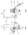
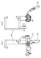
- FIG. 6 schematically and by way of example shows a force and moment sensor for the Y adjustment.
- an elastic plate 403 is strained.
- two pressure sensors S1 and S2 are arranged.
- the elastic plate 403 on the two sides of a neutral phase 404 has increased and weakened compressive forces which cause resistance changes in the sensors S1 and S2.
- the further processing of the signals takes place with the bridge circuit 405, the amplifier 406, the analog / digital converter 407, control processing 408 and a driver 409 for the stepper motor 410 for servo adjustment of the axis A4.
Landscapes
- Engineering & Computer Science (AREA)
- General Engineering & Computer Science (AREA)
- Health & Medical Sciences (AREA)
- Mechanical Engineering (AREA)
- Life Sciences & Earth Sciences (AREA)
- Surgery (AREA)
- Molecular Biology (AREA)
- Animal Behavior & Ethology (AREA)
- Oral & Maxillofacial Surgery (AREA)
- Pathology (AREA)
- Veterinary Medicine (AREA)
- Public Health (AREA)
- Biomedical Technology (AREA)
- Heart & Thoracic Surgery (AREA)
- Medical Informatics (AREA)
- Physics & Mathematics (AREA)
- Nuclear Medicine, Radiotherapy & Molecular Imaging (AREA)
- General Health & Medical Sciences (AREA)
- General Physics & Mathematics (AREA)
- Optics & Photonics (AREA)
- Microscoopes, Condenser (AREA)
Claims (14)
- Support avec un microscope chirurgical, le microscope (111) comportant en tout jusqu'à six degrés de liberté et étant fixé par l'intermédiaire d'éléments du support (102, 103, 106, 108) à une suspension (109, 110) qui comporte deux axes de pivotement (A1, A2) verticaux, qui ne sont pas influencés par la force de gravité, et un parallélogramme articulé (105) avec équilibrage de poids pour le réglage en hauteur, lesquels sont réalisés avec une mobilité aisée et avec des freins pour l'immobilisation, le microscope étant monté sur le support par l'intermédiaire d'un troisième axe (A3) vertical, qui n'est pas influencé par la force de gravité, d'un premier axe supplémentaire (A4) perpendiculaire à celui-ci et d'un deuxième axe supplémentaire (A5) perpendiculaire au premier axe supplémentaire, les axes supplémentaires (A4, A5) étant sensiblement perpendiculaires à l'axe optique de l'objectif (116) du microscope et étant conçus de manière réglable par moteur, et l'axe supplémentaire (A5) le plus proche du microscope (111) permettant un pivotement latéral du sens d'observation (direction X) et l'axe supplémentaire (A4), agencé entre le troisième axe (A3) vertical et l'axe supplémentaire (A5) le plus proche du microscope (111), permettant un pivotement du sens d'observation vers l'avant et l'arrière ou vers le haut et le bas (direction Y).
- Support selon la revendication 1, caractérisé en ce que les entraînements motorisés (410) sont conçus sous forme de servomoteurs.
- Support selon la revendication 2, caractérisé en ce que, pour la commande des servomoteurs, des capteurs de force ou de couple de rotation (S1, S2) sont agencés entre le microscope (111) et au moins un élément de commande (115), lesquels capteurs, en fonction de la valeur et de la direction de la force ou du couple de rotation exercés sur les éléments de commande, génèrent des signaux pour la commande appropriée des moteurs (410).
- support selon la revendication 3, caractérisé en ce que les éléments de commande (115) sont réglables sans entraîner une variation de la position des capteurs (S1, S2) par rapport au microscope (111).
- Support selon la revendication 3 ou 4, caractérisé en ce que les capteurs (S1, S2) sont agencés par paires, en ce que, sous l'effet d'une force exercée par une personne de service sur l'élément de commande (115), un capteur (S1, S2) est déchargé, l'autre (S2, S1) est sollicité.
- Support selon la revendication 5, caractérisé en ce que les capteurs (S1, S2) sont agencés dans un circuit en pont (405), qui délivre une tension déterminant la direction et la vitesse du réglage motorisé.
- Support selon la revendication 6, caractérisé en ce qu'il comporte des circuits (406-409) destinés à transformer la tension en une tension d'alimentation pour la servocommande (204, 206).
- Support selon la revendication 6, caractérisé en ce qu'il comporte des moteurs pas à pas (410) pour la servocommande (204, 206), des convertisseurs analogique-numérique (407) pour la tension et des circuits de régénération des signaux (408, 409) pour les signaux de sortie des convertisseurs analogique-numérique (407) en vue de générer les signaux d'activation pour les moteurs pas à pas (410).
- Support selon l'une quelconque des revendications 1 à 8, caractérisé en ce que les entraînements comportent des engrenages.
- Support selon l'une quelconque des revendications 1 à 9, caractérisé en ce que les mouvements possibles autour des différents axes sont limités.
- Support selon l'une quelconque des revendications 3 à 10, caractérisé en ce que les capteurs (S1, S2) comportent des capteurs optiques à courtes trajectoires.
- Support selon l'une quelconque des revendications 3 à 10, caractérisé en ce que les capteurs (S1, S2) comportent des capteurs capacitifs.
- Support selon l'une quelconque des revendications 3 à 10, caractérisé en ce que les capteurs (S1, S2) comportent des capteurs inductifs à courtes trajectoires.
- Support selon l'une quelconque des revendications 3 à 10, caractérisé en ce que les capteurs (S1, S2) comportent des éléments piézo-électriques.
Priority Applications (5)
| Application Number | Priority Date | Filing Date | Title |
|---|---|---|---|
| AT00108786T ATE315762T1 (de) | 2000-04-25 | 2000-04-25 | Stativ mit einem operationsmikroskop |
| EP00108786A EP1152182B1 (fr) | 2000-04-25 | 2000-04-25 | Support avec un microscope chirurgical |
| DE50012038T DE50012038D1 (de) | 2000-04-25 | 2000-04-25 | Stativ mit einem Operationsmikroskop |
| US09/841,338 US6471165B2 (en) | 2000-04-25 | 2001-04-24 | Surgical microscope and stand assembly |
| JP2001128182A JP2001309928A (ja) | 2000-04-25 | 2001-04-25 | 外科用顕微鏡 |
Applications Claiming Priority (1)
| Application Number | Priority Date | Filing Date | Title |
|---|---|---|---|
| EP00108786A EP1152182B1 (fr) | 2000-04-25 | 2000-04-25 | Support avec un microscope chirurgical |
Publications (2)
| Publication Number | Publication Date |
|---|---|
| EP1152182A1 EP1152182A1 (fr) | 2001-11-07 |
| EP1152182B1 true EP1152182B1 (fr) | 2006-01-11 |
Family
ID=8168548
Family Applications (1)
| Application Number | Title | Priority Date | Filing Date |
|---|---|---|---|
| EP00108786A Expired - Lifetime EP1152182B1 (fr) | 2000-04-25 | 2000-04-25 | Support avec un microscope chirurgical |
Country Status (5)
| Country | Link |
|---|---|
| US (1) | US6471165B2 (fr) |
| EP (1) | EP1152182B1 (fr) |
| JP (1) | JP2001309928A (fr) |
| AT (1) | ATE315762T1 (fr) |
| DE (1) | DE50012038D1 (fr) |
Cited By (1)
| Publication number | Priority date | Publication date | Assignee | Title |
|---|---|---|---|---|
| DE102007006891A1 (de) * | 2007-02-13 | 2008-08-14 | University Of Dundee | Haltevorrichtung für medizinische Zwecke |
Families Citing this family (80)
| Publication number | Priority date | Publication date | Assignee | Title |
|---|---|---|---|---|
| US4663375A (en) * | 1984-05-15 | 1987-05-05 | Mitsubishi Petrochemical Co., Ltd. | Process for producing heat-resisting moldings |
| US20040189847A1 (en) * | 2000-03-08 | 2004-09-30 | Dazor Manufacturing Corp. | Video magnification inspection system |
| USD503732S1 (en) * | 2003-07-31 | 2005-04-05 | Dazor Manufacturing Corp. | Video magnification system |
| US20030101677A1 (en) * | 2000-07-12 | 2003-06-05 | Hewett Frank W. | Joining system for tubular members |
| DE50113749D1 (de) * | 2000-09-22 | 2008-04-30 | Leica Microsystems Schweiz Ag | Mikrosokop mit einer Handhabe bzw. Handgriff für ein Mikroskop |
| DE50111444D1 (de) * | 2000-09-28 | 2006-12-28 | Leica Microsystems Schweiz Ag | Stativ |
| DE10133018A1 (de) * | 2001-07-06 | 2003-01-16 | Leica Mikroskopie Systeme Ag H | Stativ |
| EP1433225B1 (fr) * | 2001-10-03 | 2006-01-04 | Steris, Inc. | Systeme de raccord rapide pour video/donnees destine a surveiller les bras de suspension |
| US6539333B1 (en) * | 2002-01-04 | 2003-03-25 | Leica Microsystems Ag | Stand having an automatic balancing device |
| DE10300620B4 (de) * | 2002-05-18 | 2017-04-13 | Carl Zeiss Meditec Ag | Trägervorrichtung für ein medizinisch-optisches Gerät |
| US7207531B2 (en) * | 2002-12-17 | 2007-04-24 | Piontkowski Paul K | Head manipulable binocular microscope support |
| JP4270889B2 (ja) * | 2003-01-15 | 2009-06-03 | オリンパス株式会社 | 医療用器具保持装置 |
| DE102004008381B4 (de) * | 2003-06-30 | 2014-09-25 | Carl Zeiss Meditec Ag | Haltevorrichtung, insbesondere für ein medizinisch-optisches Instrument, mit Mitteln zum Ausgleich eines Last-Drehmoments sowie ein Verfahren zum Einstellen eines Gleichgewichtszustandes in einer Haltevorrichtung |
| JP4532188B2 (ja) * | 2003-06-30 | 2010-08-25 | カール−ツアイス−スチフツング | 負荷回転モーメントを補償する手段を有する、殊に医療用光学器具のための保持装置 |
| US7170250B2 (en) * | 2003-06-30 | 2007-01-30 | Carl Zeiss Surgical Gmbh | Holding arrangement having a device for actively damping vibration |
| DE102004063606B4 (de) * | 2004-02-20 | 2015-10-22 | Carl Zeiss Meditec Ag | Haltevorrichtung, insbesondere für ein medizinisch-optisches Instrument, mit einer Einrichtung zur aktiven Schwingungsdämpfung |
| JP2007533956A (ja) * | 2003-08-06 | 2007-11-22 | インテスト コーポレイション | テストヘッド位置決めシステム |
| US20050052531A1 (en) * | 2003-09-04 | 2005-03-10 | Chapman/Leonard Studio Equipment | Stabilized camera platform system |
| US7849978B2 (en) * | 2003-10-13 | 2010-12-14 | Hill-Rom Services, Inc. | Brake system for patient care equipment support arm |
| JP4486381B2 (ja) * | 2004-02-27 | 2010-06-23 | 株式会社コーナン・メディカル | 耳鼻科診察設備用の顕微鏡アーム |
| US7420731B2 (en) * | 2004-12-14 | 2008-09-02 | Piontkowski Paul K | Surgical microscope support system |
| US7770247B2 (en) * | 2005-05-02 | 2010-08-10 | Hill-Rom Services, Inc. | Brake system for wall arm |
| US7364127B2 (en) * | 2005-06-07 | 2008-04-29 | Ming-Hua Huang | Support arm for a monitor |
| DE102005031557B4 (de) | 2005-07-06 | 2021-08-05 | Carl Zeiss Meditec Ag | Operationsmikroskop-Trägersystem |
| DE102007009543A1 (de) * | 2007-02-27 | 2008-08-28 | Leica Microsystems (Schweiz) Ag | Mikroskopgerät mit Positionserfassung |
| US8025078B2 (en) | 2008-04-29 | 2011-09-27 | Illinois Tool Works Inc. | Vehicle mountable arm for valve operating machine |
| DE102008059331B4 (de) * | 2008-11-27 | 2012-05-31 | Siemens Aktiengesellschaft | Stativ, insbesondere Bodenstativ |
| EP2430436A1 (fr) * | 2009-05-14 | 2012-03-21 | Westinghouse Electric Company LLC | Systeme d'inspection de tube sans câble d'attache |
| USD637219S1 (en) * | 2009-06-26 | 2011-05-03 | Carl Zeiss Surgical Gmbh | Assembly of an XY-coupling supporting a carrier arm holding a housing containing one or two microscope bodies |
| USD649992S1 (en) | 2009-12-22 | 2011-12-06 | Carl Zeiss Meditec Ag | Stand for microscope assembly |
| DE102010010133A1 (de) * | 2010-03-04 | 2011-09-08 | Leica Microsystems (Schweiz) Ag | Stativ für ein Mikroskop, insbesondere für ein Operationsmikroskop |
| WO2011116812A1 (fr) * | 2010-03-22 | 2011-09-29 | Brainlab Ag | Commande d'un microscope chirurgical |
| TW201200316A (en) * | 2010-06-21 | 2012-01-01 | Univ Nat Taiwan | Sustaining manipulator arm |
| US8922884B2 (en) * | 2010-10-07 | 2014-12-30 | Global Surgical Corporation | Flexible objective lens assembly and microscope |
| US8851121B2 (en) | 2010-12-06 | 2014-10-07 | Illlinois Tool Works Inc. | Torque multiplier for valve turning machine |
| DE102011003589B4 (de) * | 2011-02-03 | 2017-10-26 | Carl Zeiss Meditec Ag | Stativ für eine medizinische Vorrichtung |
| DE102011004926A1 (de) * | 2011-03-01 | 2012-09-06 | Karl Storz Gmbh & Co. Kg | Einstellbare Haltevorrichtung für ein Endoskop |
| US8960632B2 (en) | 2011-07-05 | 2015-02-24 | Mediamounts, Ltd. | Dual bar linkage monitor support with adustment feature |
| US8584994B2 (en) * | 2011-10-21 | 2013-11-19 | Endure Medical, Inc. | Floor stand with angled arm for microscope |
| USD685405S1 (en) * | 2011-10-21 | 2013-07-02 | Endure Medical, Inc. | Floor stand with angled arm for microscope |
| DE102012209594B3 (de) * | 2012-06-06 | 2013-06-06 | Leica Microsystems (Schweiz) Ag | Stativ |
| US8817352B2 (en) * | 2012-09-05 | 2014-08-26 | Raytheon Company | Optical switching assembly with over-center lock |
| US9487100B2 (en) * | 2012-09-14 | 2016-11-08 | General Electric Company | Electrical vehicle charging device having a brake to prevent extension and retraction of the power conduit |
| EP2853798A1 (fr) * | 2013-09-25 | 2015-04-01 | Brunson Instrument Company | Système d'assemblage de support d'imagerie de liaison à quatre barres et procédé |
| DE102013016369A1 (de) * | 2013-09-30 | 2015-04-02 | Karl Kaps Gmbh & Co. Kg | Verstellbares Stativ für ein optisches Beobachtungsgerät |
| EP3119314B1 (fr) * | 2014-03-17 | 2020-05-06 | Intuitive Surgical Operations, Inc. | Système et procédé d'embrayage de séparation dans un bras articulé |
| USD836693S1 (en) * | 2014-06-30 | 2018-12-25 | Carl Zeiss Meditec Ag | Stand for a surgical microscope |
| USD836692S1 (en) * | 2014-06-30 | 2018-12-25 | Carl Zeiss Meditec Ag | Surgical microscope |
| JP6666249B2 (ja) * | 2014-08-01 | 2020-03-13 | ソニー・オリンパスメディカルソリューションズ株式会社 | 医療用観察装置 |
| JP6676061B2 (ja) | 2014-10-27 | 2020-04-08 | インテュイティブ サージカル オペレーションズ, インコーポレイテッド | 統合された手術台運動のためのシステム及び方法 |
| CN110584789B (zh) * | 2014-10-27 | 2022-09-20 | 直观外科手术操作公司 | 用于器械干扰补偿的系统和方法 |
| EP3212150B1 (fr) | 2014-10-27 | 2021-08-11 | Intuitive Surgical Operations, Inc. | Système pour enregistrer une table chirurgicale |
| JP6682512B2 (ja) | 2014-10-27 | 2020-04-15 | インテュイティブ サージカル オペレーションズ, インコーポレイテッド | 一体化された手術台のシステム及び方法 |
| KR102655083B1 (ko) | 2014-10-27 | 2024-04-08 | 인튜어티브 서지컬 오퍼레이션즈 인코포레이티드 | 브레이크 해제가 능동적으로 제어되는 의료 장치 |
| EP3212148B1 (fr) | 2014-10-27 | 2025-07-09 | Intuitive Surgical Operations, Inc. | Système associé à des icônes intégrées à une table chirurgicale |
| WO2016069660A1 (fr) | 2014-10-27 | 2016-05-06 | Intuitive Surgical Operations, Inc. | Système et procédé de surveillance de points de commande pendant un mouvement réactif |
| CN105982679A (zh) * | 2015-02-04 | 2016-10-05 | 深圳迈瑞生物医疗电子股份有限公司 | X线摄影系统及其摇摆臂机构 |
| CN107407863A (zh) * | 2015-04-07 | 2017-11-28 | 加勒特·W·布朗 | 用于负载稳定器的平衡支撑接口 |
| DE102016200214B4 (de) * | 2016-01-11 | 2021-06-10 | Carl Zeiss Meditec Ag | Stativ und Verfahren für die Drehmomentkompensation |
| US10767811B2 (en) * | 2016-02-24 | 2020-09-08 | Stryker Corporation | Brake control system for suspensions |
| DE102016206541A1 (de) * | 2016-04-19 | 2017-10-19 | Carl Zeiss Meditec Ag | Ophthalmologische Untersuchungs- und/oder Therapievorrichtung mit koppelbaren Gelenkarmen |
| US10203064B2 (en) | 2016-04-29 | 2019-02-12 | GCX Corporation | Locking release mechanism for an articulated support arm |
| US9772497B1 (en) * | 2016-09-23 | 2017-09-26 | Robert Troy Hewlett | Customized viewing system for an optical device |
| WO2018204612A1 (fr) * | 2017-05-03 | 2018-11-08 | Lsi Solutions, Inc. | Support d'équipement chirurgical |
| EP3600125B1 (fr) | 2017-05-03 | 2024-09-11 | LSI Solutions, Inc. | Support d'équipement chirurgical |
| JP1628319S (fr) * | 2018-02-13 | 2019-04-01 | ||
| CN108591791B (zh) * | 2018-07-13 | 2023-06-23 | 桂林智神信息技术股份有限公司 | 稳定器用机架组件及稳定器 |
| ES2929210T3 (es) * | 2018-07-25 | 2022-11-25 | American Sterilizer Co | Accionador de freno para sistema de soporte de dispositivos médicos |
| USD947918S1 (en) * | 2018-09-18 | 2022-04-05 | Carl Zeiss Meditec Ag | Surgical microscope with stand |
| EP3693642B1 (fr) | 2019-01-17 | 2022-06-15 | Illinois Tool Works, Inc. | Dispositif de fonctionnement de soupape doté d'un bras mobile destiné à être utilisé dans des soupapes d'exercice |
| USD1010315S1 (en) | 2019-09-06 | 2024-01-09 | Carl Zeiss Meditec Ag | Surgical microscope |
| CN113040905B (zh) * | 2019-12-27 | 2025-06-27 | 重庆海扶医疗科技股份有限公司 | 用于控制手术器械末端执行器的操作器 |
| CN113040911B (zh) * | 2019-12-27 | 2022-08-19 | 重庆海扶医疗科技股份有限公司 | 一种手术系统、手术系统控制及手术系统的控制方法 |
| USD934327S1 (en) | 2020-03-11 | 2021-10-26 | Carl Zeiss Meditec Ag | Surgical microscope |
| USD934937S1 (en) | 2020-03-11 | 2021-11-02 | Carl Zeiss Meditec Ag | Surgical microscope |
| CN111772823B (zh) * | 2020-06-23 | 2021-05-11 | 苏州昊信精密机械有限公司 | 手术显微镜支撑臂 |
| CN112013217A (zh) * | 2020-08-25 | 2020-12-01 | 杭州新汉杰科技有限公司 | 一种计算机显示器支架调节机构 |
| CN116322550A (zh) * | 2020-09-30 | 2023-06-23 | 奥瑞斯健康公司 | 机器人外科手术中用于术中患者定位的引导协调式床运动 |
| US20240197433A1 (en) * | 2022-12-20 | 2024-06-20 | Johnson & Johnson Surgical Vision, Inc. | Real-time 3d anatomical mapping of the eye |
| JP2026508495A (ja) * | 2023-03-02 | 2026-03-11 | アルコン インコーポレイティド | 眼科手術に最適化されたキネマティクスを有する視覚化ロボット |
Family Cites Families (17)
| Publication number | Priority date | Publication date | Assignee | Title |
|---|---|---|---|---|
| DE7930126U1 (de) * | 1979-07-24 | 1980-01-24 | Contraves Ag, Zuerich (Schweiz) | Stativ fuer ein optisches beobachtungsgeraet |
| DE7930125U1 (de) * | 1979-07-24 | 1980-01-24 | Contraves Ag, Zuerich (Schweiz) | Zusatzvorrichtung an einem stativ fuer ein optisches beobachtungsgeraet |
| US4548373A (en) * | 1983-03-22 | 1985-10-22 | Tokyo Kogaku Kikai Kabushiki Kaisha | Medical equipment supporting device |
| JPS63296743A (ja) * | 1987-05-29 | 1988-12-02 | Mitaka Koki Kk | 医療用光学機器のスタンド装置 |
| DE3921857A1 (de) | 1989-07-04 | 1991-01-17 | Wild Leitz Ag | Mit zusatzvorrichtungen ausgestattetes stativ fuer die halterung eines frei positionierbaren geraetes |
| US5273039A (en) * | 1989-10-16 | 1993-12-28 | Olympus Optical Co., Ltd. | Surgical microscope apparatus having a function to display coordinates of observation point |
| US5186422A (en) * | 1992-01-17 | 1993-02-16 | Kesanori Sahara | Stand apparatus for medical optical instrument |
| DE4202922A1 (de) | 1992-02-01 | 1993-08-05 | Zeiss Carl Fa | Motorisches stativ |
| DE4334069A1 (de) | 1993-06-21 | 1995-04-13 | Zeiss Carl Fa | Ausbalancierbares Stativ |
| DE4320443C2 (de) | 1993-06-21 | 2001-08-02 | Zeiss Carl | Ausbalancierbares Stativ |
| US5609316A (en) * | 1995-09-05 | 1997-03-11 | Tigliev; George S. | Suspension system for surgical microscope |
| JP3022760B2 (ja) * | 1996-02-26 | 2000-03-21 | 三鷹光器株式会社 | 医療用スタンド装置の機器支持構造 |
| JP3377740B2 (ja) * | 1996-12-16 | 2003-02-17 | 株式会社三協精機製作所 | 力補助装置の制御方法及びこの方法を利用した制御装置 |
| US6216056B1 (en) * | 1996-12-16 | 2001-04-10 | Kabushiki Kaisha Sanyo Seiki Seisakusho | Method of controlling force assisting device and control apparatus using the same |
| DE19732212B4 (de) * | 1997-07-26 | 2011-12-29 | Carl Zeiss | Operationsmikroskop und Stativ zur Aufnahme des Operationsmikroskopes |
| JP4083316B2 (ja) * | 1998-10-01 | 2008-04-30 | オリンパス株式会社 | 手術用顕微鏡 |
| EP1067419B1 (fr) * | 1999-07-03 | 2008-01-30 | Leica Microsystems AG | Support fixé au plafond |
-
2000
- 2000-04-25 AT AT00108786T patent/ATE315762T1/de not_active IP Right Cessation
- 2000-04-25 DE DE50012038T patent/DE50012038D1/de not_active Expired - Lifetime
- 2000-04-25 EP EP00108786A patent/EP1152182B1/fr not_active Expired - Lifetime
-
2001
- 2001-04-24 US US09/841,338 patent/US6471165B2/en not_active Expired - Lifetime
- 2001-04-25 JP JP2001128182A patent/JP2001309928A/ja active Pending
Cited By (1)
| Publication number | Priority date | Publication date | Assignee | Title |
|---|---|---|---|---|
| DE102007006891A1 (de) * | 2007-02-13 | 2008-08-14 | University Of Dundee | Haltevorrichtung für medizinische Zwecke |
Also Published As
| Publication number | Publication date |
|---|---|
| EP1152182A1 (fr) | 2001-11-07 |
| DE50012038D1 (de) | 2006-04-06 |
| US20020014562A1 (en) | 2002-02-07 |
| JP2001309928A (ja) | 2001-11-06 |
| ATE315762T1 (de) | 2006-02-15 |
| US6471165B2 (en) | 2002-10-29 |
Similar Documents
| Publication | Publication Date | Title |
|---|---|---|
| EP1152182B1 (fr) | Support avec un microscope chirurgical | |
| DE69716018T2 (de) | Verfahren und Steuerungsgerät zur Steuerung einer Krafthilfeeinrichtung | |
| EP0433426B1 (fr) | Statif equipe de dispositifs accessoires, pour supporter un appareil librement orientable | |
| DE69514739T2 (de) | Chirurgische Mikroskop-Einheit | |
| DE102008011638B4 (de) | Balanciervorrichtung für Operations-Mikroskop | |
| DE3728527C2 (fr) | ||
| DE10140608A1 (de) | Vorrichtung zur Justage eines optischen Elements | |
| EP0855002A1 (fr) | Support | |
| DE602005000651T2 (de) | Mechanismus zum Gewichtsausgleich für ein Operationsmikroskop | |
| EP0476552A1 (fr) | Mécanisme vireur pour dispositifs de support pour instruments d'observation optiques | |
| DE69104486T2 (de) | Halte und positionierungsvorrichtung für ein mikroskop. | |
| EP1336885B1 (fr) | Système microscopique microchirurgical | |
| EP1336884B1 (fr) | Système de microscope microchirurgical | |
| DE10163354A1 (de) | Vorrichtung zum Halten einer optischen Betrachtungseinrichtung | |
| DE69827160T2 (de) | Medizinische bilderzeugungsvorrichtung mit bewegungsmechanismus | |
| DE7315186U (de) | Verstellbares stativ fuer ein optisches beobachtungsgeraet, insbesondere ein binokularmikroskop | |
| DE102015225183B4 (de) | Medizinische Vorrichtung mit einem medizinisch-optischen Gerät und einer Haltevorrichtung und Verfahren zum Betrieb der medizinischen Vorrichtung | |
| WO2000077589A1 (fr) | Dispositif de commande d'un appareil | |
| DE10155719A1 (de) | Operations-Mikroskop | |
| CH685653A5 (de) | Stativ mit einer mechanischen Steuereinheit für ein damit verbundenes Operationsmikroskop. | |
| WO2003081337A2 (fr) | Dispositif permettant de modifier la position angulaire d'un objet par rapport a une structure fixe | |
| DE10347733A1 (de) | Motorisch verstellbares Röntgengerät | |
| DE102004008381B4 (de) | Haltevorrichtung, insbesondere für ein medizinisch-optisches Instrument, mit Mitteln zum Ausgleich eines Last-Drehmoments sowie ein Verfahren zum Einstellen eines Gleichgewichtszustandes in einer Haltevorrichtung | |
| EP1037085B1 (fr) | Suspension pour un microscope chirugical | |
| DE10314156B9 (de) | Schwenkhalterungsanordnung und Verfahren zum Steuern einer solchen |
Legal Events
| Date | Code | Title | Description |
|---|---|---|---|
| PUAI | Public reference made under article 153(3) epc to a published international application that has entered the european phase |
Free format text: ORIGINAL CODE: 0009012 |
|
| AK | Designated contracting states |
Kind code of ref document: A1 Designated state(s): AT BE CH CY DE DK ES FI FR GB GR IE IT LI LU MC NL PT SE |
|
| AX | Request for extension of the european patent |
Free format text: AL;LT;LV;MK;RO;SI |
|
| 17P | Request for examination filed |
Effective date: 20011213 |
|
| AKX | Designation fees paid |
Free format text: AT BE CH CY DE DK ES FI FR GB GR IE IT LI LU MC NL PT SE |
|
| 17Q | First examination report despatched |
Effective date: 20041110 |
|
| GRAP | Despatch of communication of intention to grant a patent |
Free format text: ORIGINAL CODE: EPIDOSNIGR1 |
|
| RTI1 | Title (correction) |
Free format text: STAND WITH A SURGICAL MICROSCOPE |
|
| GRAS | Grant fee paid |
Free format text: ORIGINAL CODE: EPIDOSNIGR3 |
|
| GRAA | (expected) grant |
Free format text: ORIGINAL CODE: 0009210 |
|
| AK | Designated contracting states |
Kind code of ref document: B1 Designated state(s): AT BE CH CY DE DK ES FI FR GB GR IE IT LI LU MC NL PT SE |
|
| PG25 | Lapsed in a contracting state [announced via postgrant information from national office to epo] |
Ref country code: NL Free format text: LAPSE BECAUSE OF FAILURE TO SUBMIT A TRANSLATION OF THE DESCRIPTION OR TO PAY THE FEE WITHIN THE PRESCRIBED TIME-LIMIT Effective date: 20060111 Ref country code: FI Free format text: LAPSE BECAUSE OF FAILURE TO SUBMIT A TRANSLATION OF THE DESCRIPTION OR TO PAY THE FEE WITHIN THE PRESCRIBED TIME-LIMIT Effective date: 20060111 Ref country code: IE Free format text: LAPSE BECAUSE OF FAILURE TO SUBMIT A TRANSLATION OF THE DESCRIPTION OR TO PAY THE FEE WITHIN THE PRESCRIBED TIME-LIMIT Effective date: 20060111 |
|
| REG | Reference to a national code |
Ref country code: CH Ref legal event code: EP |
|
| REG | Reference to a national code |
Ref country code: IE Ref legal event code: FG4D Free format text: LANGUAGE OF EP DOCUMENT: GERMAN |
|
| REG | Reference to a national code |
Ref country code: CH Ref legal event code: NV Representative=s name: TROESCH SCHEIDEGGER WERNER AG |
|
| REF | Corresponds to: |
Ref document number: 50012038 Country of ref document: DE Date of ref document: 20060406 Kind code of ref document: P |
|
| PG25 | Lapsed in a contracting state [announced via postgrant information from national office to epo] |
Ref country code: SE Free format text: LAPSE BECAUSE OF FAILURE TO SUBMIT A TRANSLATION OF THE DESCRIPTION OR TO PAY THE FEE WITHIN THE PRESCRIBED TIME-LIMIT Effective date: 20060411 Ref country code: DK Free format text: LAPSE BECAUSE OF FAILURE TO SUBMIT A TRANSLATION OF THE DESCRIPTION OR TO PAY THE FEE WITHIN THE PRESCRIBED TIME-LIMIT Effective date: 20060411 |
|
| PG25 | Lapsed in a contracting state [announced via postgrant information from national office to epo] |
Ref country code: ES Free format text: LAPSE BECAUSE OF FAILURE TO SUBMIT A TRANSLATION OF THE DESCRIPTION OR TO PAY THE FEE WITHIN THE PRESCRIBED TIME-LIMIT Effective date: 20060422 |
|
| PG25 | Lapsed in a contracting state [announced via postgrant information from national office to epo] |
Ref country code: AT Free format text: LAPSE BECAUSE OF NON-PAYMENT OF DUE FEES Effective date: 20060425 |
|
| GBT | Gb: translation of ep patent filed (gb section 77(6)(a)/1977) |
Effective date: 20060405 |
|
| PG25 | Lapsed in a contracting state [announced via postgrant information from national office to epo] |
Ref country code: MC Free format text: LAPSE BECAUSE OF NON-PAYMENT OF DUE FEES Effective date: 20060430 Ref country code: BE Free format text: LAPSE BECAUSE OF NON-PAYMENT OF DUE FEES Effective date: 20060430 |
|
| PG25 | Lapsed in a contracting state [announced via postgrant information from national office to epo] |
Ref country code: PT Free format text: LAPSE BECAUSE OF FAILURE TO SUBMIT A TRANSLATION OF THE DESCRIPTION OR TO PAY THE FEE WITHIN THE PRESCRIBED TIME-LIMIT Effective date: 20060612 |
|
| NLV1 | Nl: lapsed or annulled due to failure to fulfill the requirements of art. 29p and 29m of the patents act | ||
| ET | Fr: translation filed | ||
| REG | Reference to a national code |
Ref country code: IE Ref legal event code: FD4D |
|
| PLBE | No opposition filed within time limit |
Free format text: ORIGINAL CODE: 0009261 |
|
| STAA | Information on the status of an ep patent application or granted ep patent |
Free format text: STATUS: NO OPPOSITION FILED WITHIN TIME LIMIT |
|
| 26N | No opposition filed |
Effective date: 20061012 |
|
| BERE | Be: lapsed |
Owner name: MOLLER-WEDEL G.M.B.H. Effective date: 20060430 |
|
| PG25 | Lapsed in a contracting state [announced via postgrant information from national office to epo] |
Ref country code: GR Free format text: LAPSE BECAUSE OF FAILURE TO SUBMIT A TRANSLATION OF THE DESCRIPTION OR TO PAY THE FEE WITHIN THE PRESCRIBED TIME-LIMIT Effective date: 20060412 |
|
| PG25 | Lapsed in a contracting state [announced via postgrant information from national office to epo] |
Ref country code: LU Free format text: LAPSE BECAUSE OF NON-PAYMENT OF DUE FEES Effective date: 20060425 |
|
| PG25 | Lapsed in a contracting state [announced via postgrant information from national office to epo] |
Ref country code: CY Free format text: LAPSE BECAUSE OF FAILURE TO SUBMIT A TRANSLATION OF THE DESCRIPTION OR TO PAY THE FEE WITHIN THE PRESCRIBED TIME-LIMIT Effective date: 20060111 |
|
| REG | Reference to a national code |
Ref country code: DE Ref legal event code: R082 Ref document number: 50012038 Country of ref document: DE Representative=s name: GLAWE DELFS MOLL PARTNERSCHAFT MBB VON PATENT-, DE |
|
| REG | Reference to a national code |
Ref country code: DE Ref legal event code: R082 Ref document number: 50012038 Country of ref document: DE Representative=s name: GLAWE DELFS MOLL PARTNERSCHAFT MBB VON PATENT-, DE Effective date: 20140211 Ref country code: DE Ref legal event code: R081 Ref document number: 50012038 Country of ref document: DE Owner name: MOELLER-WEDEL GMBH & CO. KG, DE Free format text: FORMER OWNER: MOELLER-WEDEL GMBH, 22880 WEDEL, DE Effective date: 20140211 |
|
| PGFP | Annual fee paid to national office [announced via postgrant information from national office to epo] |
Ref country code: IT Payment date: 20140428 Year of fee payment: 15 Ref country code: FR Payment date: 20140416 Year of fee payment: 15 |
|
| PGFP | Annual fee paid to national office [announced via postgrant information from national office to epo] |
Ref country code: DE Payment date: 20150623 Year of fee payment: 16 Ref country code: GB Payment date: 20150423 Year of fee payment: 16 Ref country code: CH Payment date: 20150422 Year of fee payment: 16 |
|
| PG25 | Lapsed in a contracting state [announced via postgrant information from national office to epo] |
Ref country code: IT Free format text: LAPSE BECAUSE OF NON-PAYMENT OF DUE FEES Effective date: 20150425 |
|
| REG | Reference to a national code |
Ref country code: FR Ref legal event code: ST Effective date: 20151231 |
|
| PG25 | Lapsed in a contracting state [announced via postgrant information from national office to epo] |
Ref country code: FR Free format text: LAPSE BECAUSE OF NON-PAYMENT OF DUE FEES Effective date: 20150430 |
|
| REG | Reference to a national code |
Ref country code: DE Ref legal event code: R119 Ref document number: 50012038 Country of ref document: DE |
|
| REG | Reference to a national code |
Ref country code: CH Ref legal event code: PL |
|
| GBPC | Gb: european patent ceased through non-payment of renewal fee |
Effective date: 20160425 |
|
| PG25 | Lapsed in a contracting state [announced via postgrant information from national office to epo] |
Ref country code: DE Free format text: LAPSE BECAUSE OF NON-PAYMENT OF DUE FEES Effective date: 20161101 Ref country code: GB Free format text: LAPSE BECAUSE OF NON-PAYMENT OF DUE FEES Effective date: 20160425 Ref country code: LI Free format text: LAPSE BECAUSE OF NON-PAYMENT OF DUE FEES Effective date: 20160430 Ref country code: CH Free format text: LAPSE BECAUSE OF NON-PAYMENT OF DUE FEES Effective date: 20160430 |