EP1151833A2 - Dispositif pour positionner des feuilles dans une station de machine - Google Patents
Dispositif pour positionner des feuilles dans une station de machine Download PDFInfo
- Publication number
- EP1151833A2 EP1151833A2 EP01110900A EP01110900A EP1151833A2 EP 1151833 A2 EP1151833 A2 EP 1151833A2 EP 01110900 A EP01110900 A EP 01110900A EP 01110900 A EP01110900 A EP 01110900A EP 1151833 A2 EP1151833 A2 EP 1151833A2
- Authority
- EP
- European Patent Office
- Prior art keywords
- sheet
- clamping member
- tablet
- upright
- articulated
- Prior art date
- Legal status (The legal status is an assumption and is not a legal conclusion. Google has not performed a legal analysis and makes no representation as to the accuracy of the status listed.)
- Granted
Links
Images

Classifications
-
- B—PERFORMING OPERATIONS; TRANSPORTING
- B65—CONVEYING; PACKING; STORING; HANDLING THIN OR FILAMENTARY MATERIAL
- B65H—HANDLING THIN OR FILAMENTARY MATERIAL, e.g. SHEETS, WEBS, CABLES
- B65H5/00—Feeding articles separated from piles; Feeding articles to machines
- B65H5/08—Feeding articles separated from piles; Feeding articles to machines by grippers, e.g. suction grippers
-
- B—PERFORMING OPERATIONS; TRANSPORTING
- B65—CONVEYING; PACKING; STORING; HANDLING THIN OR FILAMENTARY MATERIAL
- B65H—HANDLING THIN OR FILAMENTARY MATERIAL, e.g. SHEETS, WEBS, CABLES
- B65H5/00—Feeding articles separated from piles; Feeding articles to machines
- B65H5/08—Feeding articles separated from piles; Feeding articles to machines by grippers, e.g. suction grippers
- B65H5/14—Details of grippers; Actuating-mechanisms therefor
-
- B—PERFORMING OPERATIONS; TRANSPORTING
- B65—CONVEYING; PACKING; STORING; HANDLING THIN OR FILAMENTARY MATERIAL
- B65H—HANDLING THIN OR FILAMENTARY MATERIAL, e.g. SHEETS, WEBS, CABLES
- B65H2301/00—Handling processes for sheets or webs
- B65H2301/40—Type of handling process
- B65H2301/44—Moving, forwarding, guiding material
- B65H2301/443—Moving, forwarding, guiding material by acting on surface of handled material
- B65H2301/4433—Moving, forwarding, guiding material by acting on surface of handled material by means holding the material
- B65H2301/44331—Moving, forwarding, guiding material by acting on surface of handled material by means holding the material at particular portion of handled material
-
- B—PERFORMING OPERATIONS; TRANSPORTING
- B65—CONVEYING; PACKING; STORING; HANDLING THIN OR FILAMENTARY MATERIAL
- B65H—HANDLING THIN OR FILAMENTARY MATERIAL, e.g. SHEETS, WEBS, CABLES
- B65H2403/00—Power transmission; Driving means
- B65H2403/50—Driving mechanisms
- B65H2403/53—Articulated mechanisms
- B65H2403/531—Planar mechanisms
- B65H2403/5311—Parallelogram mechanisms
Definitions
- the present invention relates to a device for positioning sheets in a station of a sheet processing machine, comprising a mobile tablet intended to support at least one marginal area of a sheet, actuator means causing the tablet to move in its plane, and pinching means accompanying the tablet in said displacement, capable of grasping the said marginal zone of a sheet between a leaf clip organ and tablet, and release it.
- the sheets In machines for processing sheets of paper, cardboard compact, corrugated board, such as station forming presses multiple, the sheets must be positioned very precisely too both in the longitudinal direction than in the transverse direction in each of the stations they pass through.
- a transport device such as a clamp bar, comprising a plurality of clamps mounted on a crossbar, integral with side chains, subsequently carrying this sheet in the following machine processing stations, such as cutting station, waste ejection station and others.
- Terms "front”, “longitudinal”, “transverse” and “lateral” are used here by reference in the sense that the sheets are advancing through the machine. In these stations, the problem of positioning the sheet is solved through the positioning of the shaping tools in relation to the stop positions of the clamp bar. The precision and productivity of the processing steps following are therefore conditioned by the precision of the gripping.
- the stacks of sheets are brought on a pallet and introduced into a feeder.
- the feeder ensures a regular feeding of the leaves towards the margin table, which trains the sheets in a sheet, allows them to be gripped and their introduction to the following stations.
- the sheet is jogged on the margin table against front and side cleats by means of advancement devices such as rollers or strips of materials upper elastic bands, descending on the table, or a pair pebbles arranged above and below the table.
- advancement devices such as rollers or strips of materials upper elastic bands, descending on the table, or a pair pebbles arranged above and below the table.
- the front and side cleats used are arranged exactly by compared to the references of the following stations.
- the sheet is quickly pushed against the cleats by the advancing members, then seized by a clamp bar.
- the tabs are then retracted and the clamp bar can pull the sheet in the next processing station and position it precisely compared to the tools on the turntable of this station.
- the problem of positioning is particularly delicate when the sheet has undergone one or more preliminary treatment (s), such as printing or pushing back fold lines, because the following treatments must be carried out very exactly with reference to the previous treatment. he is therefore useful to equip the positioning devices with sheets of position correction systems.
- preliminary treatment such as printing or pushing back fold lines
- Patent CH 676 695 describes a positioning device in which the cleats are motorized so as to be able to control a variation of their position and in which a printing mark or other, resulting from prior processing, can be identified by means of optoelectronic reading in order to adjust the position of the cleats, and therefore the sheet, directly according to the measured position of such a mark.
- cleat positioning devices imply that each sheet is practically stopped for the duration of its operation of jogging and adjustment, which significantly limits the frame rate sheets in the machine.
- the applicant's patent application CH 0671/99 describes a device for positioning sheets in the insertion station of a processing sheets, of the defined type of input, allowing to operate this machine at significantly higher rates.
- the leaf clip organ is present in the form of a transverse bar carrying fingers, the whole forming a comb arranged above the shelf, with uprights lateral fixed to the bar and articulated each in a single pivot point located at the level of the mobile tablet.
- the leaf-clamping organ is ordered on the one hand by a pressure spring arranged between the bar and the tablet, tending to press the fingers of the sheet-clamping member against the tablet, and on the other hand by one or two control levers of the introduction station, connected by a telescopic pendulum rod at the rear of the bar, the thrust controls the opening of the sheet clamping member by pivoting.
- the positioning process according to CH 0671/99 uses a horizontal tablet, which is driven by actuators, for example linear electric motors, on the one hand in a back and forth movement longitudinal and secondly in complementary movements of correction in longitudinal and / or transverse translation and / or in rotation around a vertical axis.
- actuators for example linear electric motors
- This process consists, from the tablet in position back of start, to engage the means of pinching the sheet on the tablet, then to control the actuators to advance the tablet and, if required, from the side and / or at an angle, depending on the coordinates readings position of the sheet by optoelectronic means, carried out during advance of the tablet, so as to bring the front edge of the sheet into the pliers of a pliers bar in a precise and predetermined position, at release the clamping means of the positioning device, then return the tablet to the rear starting position.
- the leaf-clamping organ Activation of the opening control lever (s) the leaf-clamping organ generates a shock, therefore almost a force instant; the center of inertia of this organ being distinct from its axis of pivot, the resultant of the forces has a horizontal component which acts on actuators.
- the control lever of the bar of the leaf-clamping organ exists only on one side, its thrust on the bar via a connecting rod generates a torque which interferes with a correction in rotation of the sheet position.
- the object of the present invention is to overcome the above defects.
- This goal is achieved in a device of the defined type of entry by the causes the sheet clamping member to be connected to the tablet by at least one articulation comprising a plurality of levers forming a parallelogram Speak clearly.
- the implementation of the control of opening of the sheet clamping member practically does not generate horizontal parasitic force which can be exerted on the actuators of moving the tablet carrying the sheet clamp system.
- the joint may include a fixed amount, integral with the shelf, accommodating an upper fixed pivot axis and an axis of lower fixed pivot, arranged substantially one above the other.
- the sheet clamping member is connected to the pivot by a lever actuation and a return lever forming an articulated parallelogram.
- the joint may in particular comprise a higher lever actuation, articulated in rotation in its central part around the axis of upper fixed pivot, articulated in rotation at its first end at a pinch control lever and at its second end to a movable upright, a lower return lever, articulated in rotation at its first end around the lower fixed pivot axis and articulated in rotation at its second end at the lower end of said movable upright, said movable upright being integral with the sheet clamping member.
- a spring piston acts permanently on the lever lower return, so as to apply the leaf-clamping member to the tablet.
- This type of joint inherently has a very slight radial clearance at the level of the axes, which can, at the time of opening of the leaf-clamping member, generate a parasitic effect on the tablet movement actuators.
- the movable upright secured to the sheet clamping member is connected to the fixed upright by a spring piston, articulated in rotation by its first end to said fixed amount and by its second end to said moving amount.
- This spring piston is preferably compressed in permanence.
- the device comprises an articulation at each transverse end of the sheet-clamping member, the so-called sheet-clamping member comprising a transverse beam and a plurality of fingers oriented towards the front of the device forming a first comb with the beam, arranged above from the front edge of the tablet, the so-called front edge of the tablet having the profile of a second comb, complementary to the first comb, for pinching the so-called marginal zone of a leaf between them.
- the so-called sheet-clamping member comprising a transverse beam and a plurality of fingers oriented towards the front of the device forming a first comb with the beam, arranged above from the front edge of the tablet, the so-called front edge of the tablet having the profile of a second comb, complementary to the first comb, for pinching the so-called marginal zone of a leaf between them.
- the device according to the invention can comprise at minus a leaf spring, flexible in a vertical plane and rigid in direction transverse, connecting the sheet-clamping member to a lateral upright secured to the Tablet.
- the device can comprise a pair of leaf springs, in polyester reinforced with fiberglass or more simply in steel spring, each fixed on the one hand to a substantially horizontal plate, secured to a said upright, and secondly to a plate secured to the end of the beam of the leaf-clamping organ.
- FIG. 1 shows, in a perspective view of 3/4 rear, the entire positioning device for gripping a press of shaping.
- a mobile tablet 1 is mounted on a frame 2 by through three actuator assemblies 3, 4, 5: the shelf 1 is articulated on three vertical pivots, a central pivot and two lateral pivots, respectively secured to three movable carriages sliding on slides longitudinal and transverse.
- the slides are supported by movable bars comprising permanent magnets forming the rotor of linear electric motors with stator resting on bases respectively in the center and on the lateral edges of the frame 2.
- Such actuators permanent magnets with good dynamic performance are available in trade; they are for example marketed by the company Etel (Switzerland) under the reference LMA11 / 50.
- the positioning device also includes position detectors not shown in the figures, namely a pair of transverse sheet front edge detection cells side by side and at least one strip of side cells allowing to detect the lateral edge of this same sheet.
- the results of the readings of these cells are processed by a microprocessor which also knows the race of shelf 1, determines the possible positioning error of the sheet relative to its theoretical position and calculates correction instructions addressed to the electric motors of the three actuator assemblies.
- the correction of the basic back-and-forth movement can result in a longitudinal translation in more or less if the sheet is a little too much in forward or backward, transverse translation if the leaf is present slightly off-center, or a rotation, induced by a translation differential of actuators 3 and 5, if the sheet is slightly askew.
- the device stops in the corrected position facing a bar of pliers open in the standby position, as shown in Figure 3, where a pliers P is shown, the front edge of the sheet being introduced into the clips the clamp bar.
- the clamps of the clamp bar close and the organ positioning device clip opens.
- the tablet returns to rear starting position, the linear motors returning to their positions respective neutrals. A new leaf feeding cycle can then to start.
- the shelf 1 is attached to each of its lateral ends to a horizontal plate 6 which, on the one hand accommodates a vertical axis 7 of an actuator group and on the other hand extends vertically upwards by a fixed upright 8, which is integral with the tablet.
- a fixed upright 8 which is integral with the tablet.
- the upright 8 has a slot 9 in the longitudinal direction of the device, in which is housed an upper actuating lever 10, which pivots around the fixed upright 8 around an upper fixed pivot axis 11, an axis which can be produced under shape of a smooth bushing crossing the two branches of the fixed upright and the upper actuation lever.
- the lever 10 has at its first end a pair of pin 12 holes on which a lever is articulated for controlling the pinching means, this articulation being able to take place by means of a connecting rod (not shown in the figures).
- the upper actuation lever 10 is articulated around an axis of rotation 13, to a movable upright 14.
- the axis of rotation 13 can itself be achieved by means of a smooth sleeve.
- the amount mobile 14 is secured to the lateral ends of a transverse beam 15.
- the transverse beam 15 carries fingers 16 oriented towards the front, regularly spaced, forming a comb with the transverse beam 15 and constituting with it the leaf-clamping organ.
- the upright 14 extends downward, as can be seen on Figure 2; at its lower end, it is articulated in rotation, around an axis horizontal 17 at the second end of a lower return lever 18, the first end is articulated in rotation around an axis 19 to the fixed upright 8.
- the axes 17 and 19 can be produced by means of smooth sockets.
- the fixed amount 8, the upper actuation lever 10, the amount mobile 14 and the lower return lever 18 constitute a parallelogram Speak clearly.
- the sheet clamping member, integral with the upright 14, describes a translational movement.
- this movement of translation can be considered a vertical translation, because the axes 11 and 19 are located almost vertically one above the other and the movement of the actuation lever 10 is carried out on either side of a perpendicular to a perpendicular to and connecting these two axes, on an angle relatively small.
- the return lever 18 carries an upper protrusion 20, itself carrying a side pin 21.
- a piston 22 with spring 23 compressed in permanently mounted on the plate 6 acts permanently on the pin 21 of so as to fold the lever 18 horizontally and therefore to maintain the sheet clamping member applied against the shelf 1 in the closed position.
- a lever control (not shown) articulated at axis 12, acts on the piston 22, via the articulated parallelogram, overcoming the force of the spring 23, to open the leaf clip organ.
- the device includes a second spring piston 24, articulated in rotation on the one hand to the fixed upright 8 and on the other hand to the mobile upright 14 in order to be able to follow the deformations of the parallelogram.
- the spring piston 24 is arranged substantially parallel to levers 10 and 18, and the spring of this spring piston 24 is permanently compressed. Therefore it exerts a permanent force, substantially perpendicular to axes 11, 13, 17 and 19 and maintains the maximum spacing between the axes 11 and 13 on the one hand, 17 and 19 on the other hand, so that the radial clearance is eliminated.
- the device comprises two identical joints, arranged symmetrically at the two ends of the beam 15 of the sheet clamping member.
- Two control lever systems (not shown) simultaneously exert the same action on both joints, so the process of opening the leaf clamp organ does not generate a torque which could interfere with position corrections of actuator assemblies.
- the set of two joints arranged on either side of the sheet clamping member comprises eight smooth sockets, for two times four axes, allowing the translational movement of the pinch-leaf organ from bottom to high.
- This arrangement by its nature gives a certain transverse play to the beam 15, between the two joints.
- the device comprises on either side of the beam 15, a leaf spring 25 fixed by one of its ends to a fixing plate 26 substantially horizontal, coming in one piece with the fixed upright 8 or fixed solidly to this one.
- Each leaf spring 25 is fixed by its other end to another horizontal plate 27 secured to the movable beam. In the mode shown in Figure 1, this second horizontal plate 27 constitutes a right-angle protrusion of the movable upright 14, itself integral with the beam 15.
- the leaf spring 25 is made of polyester reinforced with fiberglass. It is obvious that this leaf spring 25 could be made from another material having similar elastic characteristics.
- This blade is flexible in one plane vertical and supports the opening and closing movement of the organ leaf clamp. On the other hand, it is rigid in transverse direction and blocks a possible transverse sliding of the leaf-clamping member on the sockets constituting the axes of rotation of the articulated parallelograms.
Landscapes
- Engineering & Computer Science (AREA)
- Mechanical Engineering (AREA)
- Registering Or Overturning Sheets (AREA)
- Feeding Of Articles By Means Other Than Belts Or Rollers (AREA)
- Pile Receivers (AREA)
- Manipulator (AREA)
Abstract
Description
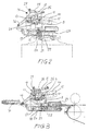
- la figure 1 montre une vue en perspective d'un dispositif selon l'invention.
- la figure 2 montre une vue en élévation latérale de l'articulation entre l'organe pince-feuilles et la tablette de la figure 1, en position ouverte.
- la figure 3 montre une vue en coupe selon le plan ... de la figure 1 de la même articulation en position fermée; ainsi qu'une pince de barre de pince et l'extrémité de la table de marge.
Claims (10)
- Dispositif pour positionner des feuilles dans une station d'une machine de traitement de feuilles, comprenant une tablette mobile (1) destinée à supporter au moins une zone marginale d'une dite feuille, des moyens actuateurs (3, 4, 5) entraínant la tablette en déplacement dans son plan, des moyens de pincement accompagnant la tablette dans le dit déplacement capables de saisir la dite zone marginale d'une feuille entre un organe pince-feuilles (15, 16) et la tablette et de la relâcher, caractérisé en ce que le dit organe pince-feuilles est relié à la tablette par au moins une articulation comprenant une pluralité de leviers (10, 18) formant un parallélogramme articulé autour d'axes de pivotement horizontaux (11, 13, 17, 19).
- Dispositif selon la revendication 1, caractérisé en ce que la dite articulation comprend un montant fixe (8), solidaire de la tablette (1), accueillant un axe de pivotement fixe supérieur (11) et un axe de pivotement fixe inférieur (19), agencés sensiblement l'un au-dessus de l'autre.
- Dispositif selon la revendication 2, caractérisé en ce que l'articulation comprend un levier supérieur d'actionnement (10), articulé en rotation en sa partie centrale autour de l'axe de pivotement fixe supérieur (11), articulé en rotation à sa première extrémité par un axe (12) à un levier de commande des moyens de pincement et à sa deuxième extrémité (13) à un montant mobile (14), un levier inférieur de rappel (18), articulé en rotation à sa première extrémité autour de l'axe de pivotement fixe inférieur (19) et articulé en rotation (17) à sa deuxième extrémité à l'extrémité inférieure du dit montant mobile, le dit montant mobile étant solidaire de l'organe pince-feuilles (15, 16).
- Dispositif selon la revendication 3, caractérisé en ce que l'articulation comprend un piston (22) à ressort (23) agissant en permanence sur le levier inférieur de rappel (18), de façon à appliquer l'organe pince-feuilles (15, 16) sur la tablette (1).
- Dispositif selon la revendication 4, caractérisé en ce que le montant mobile (14) solidaire de l'organe pince-feuilles (15, 16) est relié au dit montant fixe par un deuxième piston à ressort (24), articulé en rotation par sa première extrémité au dit montant fixe (8) et par sa deuxième extrémité au dit montant mobile (14).
- Dispositif selon la revendication 5, caractérisé en ce que le dit piston à ressort (24) est comprimé en permanence.
- Dispositif selon l'une quelconque des revendications précédentes, caractérisé par la présence d'une dite articulation à chaque extrémité transversale de l'organe pince-feuilles (15, 16), le dit organe pince-feuilles comprenant une poutre transversale (15) et une pluralité de doigts (16) orientés vers l'avant du dispositif, formant un premier peigne avec la poutre, agencé au-dessus du bord avant de la tablette (1), le dit bord avant de la tablette présentant le profil d'un deuxième peigne, complémentaire au premier peigne, pour pincer la dite zone marginale d'une feuille entre eux.
- Dispositif selon la revendication 7, caractérisé en ce qu'il comprend au moins une lame-ressort (25), flexible dans un plan vertical et rigide en direction transversale, reliant l'organe pince-feuilles (15, 16) à un montant fixe (8) latéral.
- Dispositif selon la revendication 8, caractérisé en ce qu'il comprend une paire de lames-ressort (25), en polyester armé de fibre de verre, fixées chacune d'une part à une plaquette (26) sensiblement horizontale, solidaire d'un dit montant, et d'autre part à une plaquette (27) solidaire de l'extrémité de la poutre (15) de l'organe pince-feuilles.
- Presse de façonnage de feuilles de papier ou carton, caractérisée en ce qu'elle comprend un dispositif de positionnement selon l'une quelconque des revendications précédentes, agencé entre la table de marge et la station de découpe.
Applications Claiming Priority (2)
| Application Number | Priority Date | Filing Date | Title |
|---|---|---|---|
| CH8832000 | 2000-05-05 | ||
| CH00883/00A CH693794A5 (fr) | 2000-05-05 | 2000-05-05 | Dispositif pour positionner des feuilles dans une station de machine. |
Publications (3)
| Publication Number | Publication Date |
|---|---|
| EP1151833A2 true EP1151833A2 (fr) | 2001-11-07 |
| EP1151833A3 EP1151833A3 (fr) | 2003-10-22 |
| EP1151833B1 EP1151833B1 (fr) | 2005-03-02 |
Family
ID=4545025
Family Applications (1)
| Application Number | Title | Priority Date | Filing Date |
|---|---|---|---|
| EP01110900A Expired - Lifetime EP1151833B1 (fr) | 2000-05-05 | 2001-05-05 | Dispositif pour positionner des feuilles dans une station de machine |
Country Status (13)
| Country | Link |
|---|---|
| US (1) | US6637744B2 (fr) |
| EP (1) | EP1151833B1 (fr) |
| JP (1) | JP3408801B2 (fr) |
| KR (1) | KR100424121B1 (fr) |
| CN (1) | CN1206146C (fr) |
| AT (1) | ATE289899T1 (fr) |
| AU (1) | AU778553B2 (fr) |
| BR (1) | BR0101686B1 (fr) |
| CA (1) | CA2346276C (fr) |
| CH (1) | CH693794A5 (fr) |
| DE (1) | DE60109083T2 (fr) |
| ES (1) | ES2237510T3 (fr) |
| TW (1) | TW480215B (fr) |
Cited By (1)
| Publication number | Priority date | Publication date | Assignee | Title |
|---|---|---|---|---|
| KR100424121B1 (ko) * | 2000-05-05 | 2004-03-24 | 봅스트 쏘시에떼 아노님 | 기계 스테이션에서의 시트 위치결정 장치 |
Families Citing this family (10)
| Publication number | Priority date | Publication date | Assignee | Title |
|---|---|---|---|---|
| DE10204296A1 (de) * | 2002-02-02 | 2003-08-14 | Kolbus Gmbh & Co Kg | Vorrichtung zum dreiseitigen Beschneiden von Druckprodukten |
| ES2259755T3 (es) * | 2003-10-07 | 2006-10-16 | Bobst S.A. | Estacion de trabajo de una maquina de transformacion de elementos en laminas. |
| FR2901164B1 (fr) * | 2006-05-16 | 2008-08-15 | Aro Soc Par Actions Simplifiee | Pince a enserrer des toles, utilisee en association avec un bras manipulateur, et a module d'equilibrage deporte |
| DE102010027119A1 (de) * | 2010-07-14 | 2012-01-19 | Heidelberger Druckmaschinen Ag | Verfahren und Vorrichtung zum Positionieren von Bogen |
| CN105128508B (zh) * | 2014-05-26 | 2018-10-09 | 海德堡印刷机械股份公司 | 用于印刷机的刮刀装置 |
| US9446612B1 (en) | 2015-12-11 | 2016-09-20 | Xerox Corporation | Multiple-gripper architecture for multi-sheet-length digital printing |
| CN109809236B (zh) * | 2019-04-03 | 2024-02-09 | 广州市兴世机械制造有限公司 | 带材储料用的箱式收卷设备 |
| CN110561899A (zh) * | 2019-10-08 | 2019-12-13 | 山东沃丰新材料有限公司 | 一种彩钢板印花装置及工艺 |
| KR102857076B1 (ko) * | 2021-03-08 | 2025-09-08 | 봅스트 맥스 에스에이 | 위치결정 조립체 및 시트 재료 처리 기계 |
| KR102576579B1 (ko) * | 2022-10-21 | 2023-09-11 | (주)삼원 | 원단 파지용 클램프장치 및 이를 이용한 금형방법 |
Family Cites Families (14)
| Publication number | Priority date | Publication date | Assignee | Title |
|---|---|---|---|---|
| US3929368A (en) * | 1973-05-11 | 1975-12-30 | St Clare Eng Ltd | Drum lifters |
| US4270652A (en) * | 1977-08-17 | 1981-06-02 | Am International, Inc. | Automatic collator unloader |
| DE2835416A1 (de) * | 1978-08-12 | 1980-02-21 | Will E C H Gmbh & Co | Vorrichtung zum uebergeben einer lage aus papier von einer sammelstation an einen abfoerderer |
| GB2050312B (en) * | 1979-05-29 | 1983-05-18 | Metal Box Co Ltd | Gripping mechanism for printing machine |
| US4550905A (en) * | 1984-06-27 | 1985-11-05 | The United States Of America As Represented By The Secretary Of Agriculture | Hide transfer apparatus |
| JPH01172145A (ja) * | 1987-12-26 | 1989-07-07 | Bridgestone Corp | シート状部材の挟持装置 |
| CH676695A5 (fr) * | 1988-05-19 | 1991-02-28 | Bobst Sa | |
| US5588688A (en) * | 1990-08-06 | 1996-12-31 | Sarcos, Inc. | Robotic grasping apparatus |
| US5324124A (en) * | 1993-01-28 | 1994-06-28 | International Business Machines Corporation | Guide system for feed roll entry |
| CH689639A5 (fr) * | 1994-02-24 | 1999-07-30 | Bobst Sa | Dispositif de taquage latéral d'éléments plats sur une table. |
| JPH092701A (ja) * | 1995-06-20 | 1997-01-07 | Mitsubishi Electric Corp | 用紙クランプ装置 |
| DE19739784A1 (de) * | 1997-09-10 | 1999-03-11 | Bell & Howell Co | Einrichtung zur Handhabung blattartiger Fördergutstücke |
| CH693378A5 (fr) * | 1999-04-09 | 2003-07-15 | Bobst Sa | Procédé de positionnement d'éléments en plaque dans la station d'introduction d'une machine de traitement et dispositif pour la mise en oeuvre du procédé. |
| CH693794A5 (fr) * | 2000-05-05 | 2004-02-13 | Bobst Sa | Dispositif pour positionner des feuilles dans une station de machine. |
-
2000
- 2000-05-05 CH CH00883/00A patent/CH693794A5/fr not_active IP Right Cessation
-
2001
- 2001-04-11 TW TW090108608A patent/TW480215B/zh not_active IP Right Cessation
- 2001-04-30 CN CNB011214295A patent/CN1206146C/zh not_active Expired - Lifetime
- 2001-05-02 US US09/847,742 patent/US6637744B2/en not_active Expired - Lifetime
- 2001-05-04 CA CA002346276A patent/CA2346276C/fr not_active Expired - Lifetime
- 2001-05-04 BR BRPI0101686-5A patent/BR0101686B1/pt not_active IP Right Cessation
- 2001-05-04 KR KR10-2001-0024433A patent/KR100424121B1/ko not_active Expired - Fee Related
- 2001-05-04 AU AU42069/01A patent/AU778553B2/en not_active Expired
- 2001-05-05 DE DE60109083T patent/DE60109083T2/de not_active Expired - Lifetime
- 2001-05-05 AT AT01110900T patent/ATE289899T1/de not_active IP Right Cessation
- 2001-05-05 ES ES01110900T patent/ES2237510T3/es not_active Expired - Lifetime
- 2001-05-05 EP EP01110900A patent/EP1151833B1/fr not_active Expired - Lifetime
- 2001-05-07 JP JP2001136215A patent/JP3408801B2/ja not_active Expired - Lifetime
Cited By (1)
| Publication number | Priority date | Publication date | Assignee | Title |
|---|---|---|---|---|
| KR100424121B1 (ko) * | 2000-05-05 | 2004-03-24 | 봅스트 쏘시에떼 아노님 | 기계 스테이션에서의 시트 위치결정 장치 |
Also Published As
| Publication number | Publication date |
|---|---|
| JP2002003010A (ja) | 2002-01-09 |
| BR0101686B1 (pt) | 2009-05-05 |
| KR100424121B1 (ko) | 2004-03-24 |
| EP1151833B1 (fr) | 2005-03-02 |
| CN1206146C (zh) | 2005-06-15 |
| CN1322626A (zh) | 2001-11-21 |
| EP1151833A3 (fr) | 2003-10-22 |
| CA2346276C (fr) | 2004-11-30 |
| TW480215B (en) | 2002-03-21 |
| AU778553B2 (en) | 2004-12-09 |
| US20010040334A1 (en) | 2001-11-15 |
| US6637744B2 (en) | 2003-10-28 |
| ES2237510T3 (es) | 2005-08-01 |
| KR20010100982A (ko) | 2001-11-14 |
| CH693794A5 (fr) | 2004-02-13 |
| DE60109083D1 (de) | 2005-04-07 |
| AU4206901A (en) | 2001-11-08 |
| CA2346276A1 (fr) | 2001-11-05 |
| ATE289899T1 (de) | 2005-03-15 |
| JP3408801B2 (ja) | 2003-05-19 |
| BR0101686A (pt) | 2001-12-26 |
| DE60109083T2 (de) | 2006-04-13 |
Similar Documents
| Publication | Publication Date | Title |
|---|---|---|
| EP1044908B1 (fr) | Procédé de positionnement d'éléments en plaque dans la station d'introduction d'une machine de traitement et dispositif pour la mise en oeuvre du procédé | |
| EP1151833B1 (fr) | Dispositif pour positionner des feuilles dans une station de machine | |
| FR2563757A1 (fr) | Cisaille a guillotine | |
| EP0069661B1 (fr) | Plieuse automatique de tôles | |
| CH689974A5 (fr) | Station d'éjection de déchets dans une machine de découpe d'éléments en plaque. | |
| EP0445044B1 (fr) | Machine à cintrer les tubes à deux têtes de cintrage | |
| EP0983951B1 (fr) | Dispositif correcteur à rouleaux ou à bande pour l'alignement latéral, en cours de faconnage, d'articles en feuilles ou en plaques partiellement pliés dans une plieuse-colleuse | |
| CH373688A (fr) | Procédé pour insérer une ébauche de séparation pliable entre des rangées de récipients à emballer et machine pour la mise en oeuvre de ce procédé | |
| EP3414199B1 (fr) | Dispositif de chargement de feuilles d'encart, station de reception des poses, machine de traitement d'elements en forme de feuilles et procede de transport d'une feuille d'encart | |
| EP0610791B1 (fr) | Dispositif pour aligner des découpes de boites dans une machine les travaillant | |
| EP3526025B1 (fr) | Dispositif et procédé d'extraction d'une boite formée d'un mandrin | |
| EP0741096B1 (fr) | Dispositif de transport de bandes métallisées | |
| FR2484979A1 (fr) | Procede et appareil d'assemblage de matiere en feuille, notamment pour alimenter en continu des imprimantes rapides | |
| FR2541562A1 (fr) | Procede de greffage automatique de la vigne et machine comportant application de ce procede | |
| FR2597290A1 (fr) | Procede et appareil de fabrication de faisceaux de conducteurs | |
| CH693787A5 (fr) | Procédé pour préparer un système d'outils de façonnage, table de réglage pour mettre en oeuvre ce procédé et ensemble d'éléments pour préparer une forme supérieure d'éjection. | |
| EP3526024A1 (fr) | Procédé et dispositif de mise en forme d'un flan autour d'un mandrin | |
| EP0453984A2 (fr) | Dispositif de taquage de feuilles | |
| EP0453983A1 (fr) | Dispositif d'interception de feuilles déposées sur le haut d'une pile dans une machine de production d'emballages | |
| EP0568417A1 (fr) | Installation de manutention pour le transport de flans d'une machine de découpage à un dispositif d'empilage | |
| WO2001026867A1 (fr) | Machine automatique d'assemblage de cadres | |
| EP0912265B1 (fr) | Dispositif permettant d'adapter la taille d'un serre-flan de machine-outil | |
| BE1009146A3 (fr) | Dispositif servant a coller des renforts lamellaires au fond des caisses en carton. | |
| FR2632887A1 (fr) | Guillotine automatique pour decouper du papier | |
| EP3820265A1 (fr) | Procédé et dispositif de découpe d'un composant électronique radial |
Legal Events
| Date | Code | Title | Description |
|---|---|---|---|
| PUAI | Public reference made under article 153(3) epc to a published international application that has entered the european phase |
Free format text: ORIGINAL CODE: 0009012 |
|
| 17P | Request for examination filed |
Effective date: 20010505 |
|
| AK | Designated contracting states |
Kind code of ref document: A2 Designated state(s): AT BE CH CY DE DK ES FI FR GB GR IE IT LI LU MC NL PT SE TR |
|
| AX | Request for extension of the european patent |
Free format text: AL;LT;LV;MK;RO;SI |
|
| PUAL | Search report despatched |
Free format text: ORIGINAL CODE: 0009013 |
|
| AK | Designated contracting states |
Kind code of ref document: A3 Designated state(s): AT BE CH CY DE DK ES FI FR GB GR IE IT LI LU MC NL PT SE TR |
|
| AX | Request for extension of the european patent |
Extension state: AL LT LV MK RO SI |
|
| RIC1 | Information provided on ipc code assigned before grant |
Ipc: 7B 26D 7/02 B Ipc: 7B 26D 7/01 A Ipc: 7B 65H 5/14 B |
|
| AKX | Designation fees paid |
Designated state(s): AT BE CH CY DE DK ES FI FR GB GR IE IT LI LU MC NL PT SE TR |
|
| GRAP | Despatch of communication of intention to grant a patent |
Free format text: ORIGINAL CODE: EPIDOSNIGR1 |
|
| GRAS | Grant fee paid |
Free format text: ORIGINAL CODE: EPIDOSNIGR3 |
|
| GRAA | (expected) grant |
Free format text: ORIGINAL CODE: 0009210 |
|
| AK | Designated contracting states |
Kind code of ref document: B1 Designated state(s): AT BE CH CY DE DK ES FI FR GB GR IE IT LI LU MC NL PT SE TR |
|
| PG25 | Lapsed in a contracting state [announced via postgrant information from national office to epo] |
Ref country code: TR Free format text: LAPSE BECAUSE OF FAILURE TO SUBMIT A TRANSLATION OF THE DESCRIPTION OR TO PAY THE FEE WITHIN THE PRESCRIBED TIME-LIMIT Effective date: 20050302 Ref country code: NL Free format text: LAPSE BECAUSE OF FAILURE TO SUBMIT A TRANSLATION OF THE DESCRIPTION OR TO PAY THE FEE WITHIN THE PRESCRIBED TIME-LIMIT Effective date: 20050302 Ref country code: FI Free format text: LAPSE BECAUSE OF FAILURE TO SUBMIT A TRANSLATION OF THE DESCRIPTION OR TO PAY THE FEE WITHIN THE PRESCRIBED TIME-LIMIT Effective date: 20050302 Ref country code: AT Free format text: LAPSE BECAUSE OF FAILURE TO SUBMIT A TRANSLATION OF THE DESCRIPTION OR TO PAY THE FEE WITHIN THE PRESCRIBED TIME-LIMIT Effective date: 20050302 Ref country code: IE Free format text: LAPSE BECAUSE OF FAILURE TO SUBMIT A TRANSLATION OF THE DESCRIPTION OR TO PAY THE FEE WITHIN THE PRESCRIBED TIME-LIMIT Effective date: 20050302 |
|
| REG | Reference to a national code |
Ref country code: GB Ref legal event code: FG4D Free format text: NOT ENGLISH |
|
| REG | Reference to a national code |
Ref country code: CH Ref legal event code: EP |
|
| REG | Reference to a national code |
Ref country code: IE Ref legal event code: FG4D Free format text: FRENCH |
|
| REF | Corresponds to: |
Ref document number: 60109083 Country of ref document: DE Date of ref document: 20050407 Kind code of ref document: P |
|
| GBT | Gb: translation of ep patent filed (gb section 77(6)(a)/1977) |
Effective date: 20050405 |
|
| PG25 | Lapsed in a contracting state [announced via postgrant information from national office to epo] |
Ref country code: CY Free format text: LAPSE BECAUSE OF FAILURE TO SUBMIT A TRANSLATION OF THE DESCRIPTION OR TO PAY THE FEE WITHIN THE PRESCRIBED TIME-LIMIT Effective date: 20050505 Ref country code: LU Free format text: LAPSE BECAUSE OF NON-PAYMENT OF DUE FEES Effective date: 20050505 |
|
| PG25 | Lapsed in a contracting state [announced via postgrant information from national office to epo] |
Ref country code: MC Free format text: LAPSE BECAUSE OF NON-PAYMENT OF DUE FEES Effective date: 20050531 Ref country code: BE Free format text: LAPSE BECAUSE OF NON-PAYMENT OF DUE FEES Effective date: 20050531 |
|
| PG25 | Lapsed in a contracting state [announced via postgrant information from national office to epo] |
Ref country code: GR Free format text: LAPSE BECAUSE OF FAILURE TO SUBMIT A TRANSLATION OF THE DESCRIPTION OR TO PAY THE FEE WITHIN THE PRESCRIBED TIME-LIMIT Effective date: 20050602 Ref country code: DK Free format text: LAPSE BECAUSE OF FAILURE TO SUBMIT A TRANSLATION OF THE DESCRIPTION OR TO PAY THE FEE WITHIN THE PRESCRIBED TIME-LIMIT Effective date: 20050602 |
|
| REG | Reference to a national code |
Ref country code: ES Ref legal event code: FG2A Ref document number: 2237510 Country of ref document: ES Kind code of ref document: T3 |
|
| PG25 | Lapsed in a contracting state [announced via postgrant information from national office to epo] |
Ref country code: PT Free format text: LAPSE BECAUSE OF FAILURE TO SUBMIT A TRANSLATION OF THE DESCRIPTION OR TO PAY THE FEE WITHIN THE PRESCRIBED TIME-LIMIT Effective date: 20050817 |
|
| NLV1 | Nl: lapsed or annulled due to failure to fulfill the requirements of art. 29p and 29m of the patents act | ||
| REG | Reference to a national code |
Ref country code: IE Ref legal event code: FD4D |
|
| BERE | Be: lapsed |
Owner name: BOBST S.A. Effective date: 20050531 |
|
| PLBE | No opposition filed within time limit |
Free format text: ORIGINAL CODE: 0009261 |
|
| STAA | Information on the status of an ep patent application or granted ep patent |
Free format text: STATUS: NO OPPOSITION FILED WITHIN TIME LIMIT |
|
| 26N | No opposition filed |
Effective date: 20051205 |
|
| BERE | Be: lapsed |
Owner name: BOBST S.A. Effective date: 20050531 |
|
| PG25 | Lapsed in a contracting state [announced via postgrant information from national office to epo] |
Ref country code: SE Free format text: LAPSE BECAUSE OF FAILURE TO SUBMIT A TRANSLATION OF THE DESCRIPTION OR TO PAY THE FEE WITHIN THE PRESCRIBED TIME-LIMIT Effective date: 20050602 |
|
| REG | Reference to a national code |
Ref country code: FR Ref legal event code: PLFP Year of fee payment: 16 |
|
| REG | Reference to a national code |
Ref country code: FR Ref legal event code: PLFP Year of fee payment: 17 |
|
| REG | Reference to a national code |
Ref country code: FR Ref legal event code: PLFP Year of fee payment: 18 |
|
| PGFP | Annual fee paid to national office [announced via postgrant information from national office to epo] |
Ref country code: ES Payment date: 20200601 Year of fee payment: 20 Ref country code: DE Payment date: 20200422 Year of fee payment: 20 Ref country code: CH Payment date: 20200504 Year of fee payment: 20 Ref country code: FR Payment date: 20200504 Year of fee payment: 20 |
|
| PGFP | Annual fee paid to national office [announced via postgrant information from national office to epo] |
Ref country code: IT Payment date: 20200414 Year of fee payment: 20 Ref country code: GB Payment date: 20200422 Year of fee payment: 20 |
|
| REG | Reference to a national code |
Ref country code: DE Ref legal event code: R071 Ref document number: 60109083 Country of ref document: DE |
|
| REG | Reference to a national code |
Ref country code: CH Ref legal event code: PL |
|
| REG | Reference to a national code |
Ref country code: GB Ref legal event code: PE20 Expiry date: 20210504 |
|
| PG25 | Lapsed in a contracting state [announced via postgrant information from national office to epo] |
Ref country code: GB Free format text: LAPSE BECAUSE OF EXPIRATION OF PROTECTION Effective date: 20210504 |
|
| REG | Reference to a national code |
Ref country code: ES Ref legal event code: FD2A Effective date: 20211207 |
|
| PG25 | Lapsed in a contracting state [announced via postgrant information from national office to epo] |
Ref country code: ES Free format text: LAPSE BECAUSE OF EXPIRATION OF PROTECTION Effective date: 20210506 |