EP1151819A1 - Antriebskupplung für Trommelscheren - Google Patents
Antriebskupplung für Trommelscheren Download PDFInfo
- Publication number
- EP1151819A1 EP1151819A1 EP01110750A EP01110750A EP1151819A1 EP 1151819 A1 EP1151819 A1 EP 1151819A1 EP 01110750 A EP01110750 A EP 01110750A EP 01110750 A EP01110750 A EP 01110750A EP 1151819 A1 EP1151819 A1 EP 1151819A1
- Authority
- EP
- European Patent Office
- Prior art keywords
- drive
- drum
- drums
- gear
- transmission element
- Prior art date
- Legal status (The legal status is an assumption and is not a legal conclusion. Google has not performed a legal analysis and makes no representation as to the accuracy of the status listed.)
- Granted
Links
- 238000005520 cutting process Methods 0.000 claims abstract description 11
- 230000008878 coupling Effects 0.000 claims description 16
- 238000010168 coupling process Methods 0.000 claims description 16
- 238000005859 coupling reaction Methods 0.000 claims description 16
- 230000001360 synchronised effect Effects 0.000 claims description 12
- 230000005540 biological transmission Effects 0.000 claims description 11
- 238000009826 distribution Methods 0.000 description 3
- 238000005096 rolling process Methods 0.000 description 3
- 230000002349 favourable effect Effects 0.000 description 2
- 238000004519 manufacturing process Methods 0.000 description 2
- 239000002184 metal Substances 0.000 description 2
- 230000000052 comparative effect Effects 0.000 description 1
- 238000009434 installation Methods 0.000 description 1
- 239000000463 material Substances 0.000 description 1
- 230000035939 shock Effects 0.000 description 1
- 238000009827 uniform distribution Methods 0.000 description 1
- 238000011144 upstream manufacturing Methods 0.000 description 1
Images

Classifications
-
- B—PERFORMING OPERATIONS; TRANSPORTING
- B23—MACHINE TOOLS; METAL-WORKING NOT OTHERWISE PROVIDED FOR
- B23D—PLANING; SLOTTING; SHEARING; BROACHING; SAWING; FILING; SCRAPING; LIKE OPERATIONS FOR WORKING METAL BY REMOVING MATERIAL, NOT OTHERWISE PROVIDED FOR
- B23D25/00—Machines or arrangements for shearing stock while the latter is travelling otherwise than in the direction of the cut
- B23D25/12—Shearing machines with blades on coacting rotating drums
-
- B—PERFORMING OPERATIONS; TRANSPORTING
- B23—MACHINE TOOLS; METAL-WORKING NOT OTHERWISE PROVIDED FOR
- B23D—PLANING; SLOTTING; SHEARING; BROACHING; SAWING; FILING; SCRAPING; LIKE OPERATIONS FOR WORKING METAL BY REMOVING MATERIAL, NOT OTHERWISE PROVIDED FOR
- B23D33/00—Accessories for shearing machines or shearing devices
Definitions
- the invention relates to a drive coupling for drum shears for cross cutting a running strip, in particular a rolled hot strip, comprising a pair mounted in a scissor-type frame by a pair of gears in opposite synchronous Rotation driven knife drums and an associated drive unit.
- Such drive clutches are in multiple designs in the prior art stations known, but mostly from a pair in a scissor-type structure mounted, driven by a pair of gears in opposite synchronous rotation Knife drums each only one of the drums as a drive drum trained and connected to the drive unit via a drive coupling is.
- DE laid-open specification 26 22 558 describes a pair of scissors for cutting moving belts with two, counter-rotating, mounted in scissor stands rotating knife drums, the spaced on a soleplate Scissor stand above the knife drums by a detachable Yoke are connected together and both knife drums directly in the scissor stand, which each consist of one piece, are stored, and the Scissor stand inserted in the base plate and with this by quickly detachable Brackets are connected.
- the knife drum is by an easily disengageable clutch with a drive connected.
- the clutch can be disengaged with a hydraulically displaceable Coupling sleeve should be provided.
- the scissors are driven over the lower knife shaft.
- the drive clutch does that Torque for both the lower and the upper knife drum.
- U.S. Patent 4,459,887 discloses a drum shear drive Rotor type, this upstream of a multi-stage gear with an electric motor is, the output shaft via a special power transmission element is connected, which means for setting a preselectable length of a Has rolled product.
- This version too is made up of two interacting with each other Scissor drums only drive one directly and take over in turn the synchronous drive of the second knife drum.
- GB 2 249 047 A discloses a pair of scissors for cutting a metal strip, that moves along a transport route.
- the device comprises two parallel opposite horizontal drums that run across the transport route and are arranged on opposite sides thereof. Every drum is equipped with a cutting knife and has a shaft on both Pages.
- the shafts of each drum are stored in chocks and against the other drum designed to be movable.
- Every movable chock is a hydraulic cylinder connected and arranged so that it is able to associated drum between a first position in which the two Drums are relatively apart, and in a second position in which they are relatively close to each other for cutting.
- Gear wheels comb together when the two drums are in the second Cutting position. The gear wheels synchronize the two drums.
- a speed sensor produces a signal when the two speeds reach a predetermined size and cause the movement of the Drum in the second position. Because the synchronous gears are in the first position are not combing, are via a side-mounted synchronous gear the shafts of both drums are driven separately.
- Document WO 99 36 218 discloses a flying drum shear for Cutting thin metal strips, comprising a framework, in which two drums stored with horizontally beveled knives and coupled with gear wheels are. The backlash is between the wheels and the bearings of the drums eliminated by preloaded springs.
- the side parts of the scissor scaffold are horizontally spaced, according to the width of the cutting band and form two bearing housings with anchors and horizontal Screws are connected to each other via a washer. The drive the scissors are connected to one of the drums with a backlash-free coupling.
- the object of the invention based on a design and arrangement of the drive clutch for drum shears specify a significantly more favorable torque distribution and -Introduction allows, and thus the drum pin of the drive drum from relieves high torque for both drums. Furthermore, the dimensions should the scissors, transverse to the rolling direction of the strip, and thus installation problems be reduced, especially when installed in existing systems; and after all, this also makes the manufacturing and assembly costs of the scissors clear be reduced.
- a drive clutch of the type mentioned in the preamble of claim 1 with the invention has a power transmission torque in the form of an h u Has lens-shaped double toothed part, one end of which is slipped onto the shaft journal of one of the knife drums with anti-rotation device, and is designed with external toothing as the drive gear of the synchronous gear, and the other end of which has an externally toothed flange for rotary engagement in a drive-side coupling sleeve designed to be compatible with the internal toothing owns.
- the scissors are in the new version Coupling hit and comb roller in one piece or by means of a flange connection connected, creating an extremely favorable torque distribution under Relief of the bearing journal of the drive drum is reached.
- the torque for the rotating knife drum is not over the bearing journal of the drive drum transferred, but via the power transmission element in the form of sleeve-shaped double toothed part outside of the bearing journal on the second drum transferred.
- the drum cone previously known as a "bottle neck" for the Torque transmission is now around 50% of the torque relieved. A possible risk of breakage, especially when operating a shock Drum shears are effectively reduced.
- FIG. 1 shows a drive clutch for drum shears according to the prior art, in which the lower drum 104 is designed as a drive drum, the via the cooperating synchronous gears 101, 102 (corresponding in Fig. 2 the gear pair 1 or 2) a torque from the shaft journal 105 via the gear 102 non-rotatably mounted thereon transmits to gear 101, which is connected to the shaft journal 105 '.
- the shaft journal 105 has the torques of the two Drums 103, 104 must take over together and consequently in his Cross-section is loaded accordingly, which can be particularly critical can if the scissors due to their function with sudden torque peaks is charged. This causes the torque to swell and shrink can lead to material fatigue with the risk of breakage in the long run.
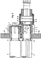
- the clutch is a power transmission element 10 in the form of a sleeve-shaped double toothing part, the one end 11 with a snug fit on the shaft journal 5 of the knife drum 4 with an anti-rotation device is pushed by a longitudinal wedge 6, and with an external toothing 7 designed as a drive gear 2 of the synchronous gear 1, 2 is.
- the other end 12 has an externally toothed flange 13 for rotational engagement in the toothing 14, which is compatible with the internal toothing 14, drive-side coupling sleeve 15.
- the force transmission element 10 or double toothing part is formed in one piece, as clearly shown in FIG. 2.
- the gears 1, 2 of the synchronous gear are with their holes 8, 8 'on the Shaft journal 5, 5 'of the knife drums 3, 4 fastened and by longitudinal shaft wedges 6, 6 'secured against rotation.
- shaft journals 5, 5 'with cylindrical roller bearings 21, 21 ' are mounted in side cheeks 20, 20' of the scissors-like structure.
- the invention is surprisingly straightforward and particularly effective by approximately uniform distribution of the drive torque over the Synchronous gear 7, 7 'of the gears 1, 2 on the two drum journals 5, 5'.
Landscapes
- Engineering & Computer Science (AREA)
- Mechanical Engineering (AREA)
- Shearing Machines (AREA)
- Harvester Elements (AREA)
- Joining Of Building Structures In Genera (AREA)
- Storage Of Web-Like Or Filamentary Materials (AREA)
- Mechanical Operated Clutches (AREA)
- Hydraulic Clutches, Magnetic Clutches, Fluid Clutches, And Fluid Joints (AREA)
Abstract
Description
- Figur 1
- eine Ausführung der Kupplung nach dem Stand der Technik, im Schnitt einer die Mittellinien beider Trommeln schneidenden Ebene;
- Figur 2
- den Gegenstand der Erfindung, ebenfalls im Schnitt einer die beiden Trommel-Mittellinien schneidenden Ebene.
Claims (5)
- Antriebskupplung für Trommelscheren zum Quertrennen eines laufenden Bandes insbesondere eines gewalzten Warmbandes, umfassend ein Paar in einem Scherengerüst gelagerte, durch ein Zahnradpaar (1, 2) in gegenläufig-synchrone Rotation antreibbare Messertrommeln (3, 4) sowie ein zugeordnetes Antriebsaggregat,
dadurch gekennzeichnet, daß die Kupplung ein Kraftübertragungselement (10) in Form eines hülsenförmigen Doppelverzahnungsteils besitzt, dessen eines Ende (11) mit Paßsitz auf dem Wellenzapfen (5) einer der Messertrommeln (4) mit Verdrehsicherung aufgeschoben ist, und mit einer Außenverzahnung (7) als Antriebszahnrad (2) des Synchrongetriebes (1,2) ausgebildet ist, und dessen anderes Ende (12) einen außenverzahnten Flansch (13) zum drehschlüssigen Eingriff in eine mit Innenverzahnung (14) kompatibel ausgebildete, antriebsseitige Kupplungshülse (15) besitzt. - Antriebskupplung nach Anspruch 1,
dadurch gekennzeichnet, daß das Kraftübertragungselement (10) bzw. Doppelverzahnungsteil einstückig ausgebildet ist. - Antriebskupplung nach Anspruch 1,
dadurch gekennzeichnet, daß das Kraftübertragungselement (10) bzw. Doppelverzahnungsteil zweiteilig in einer Trennebene quer zur Längsachse mit einer Flansch-Schraubverbindung ausgebildet ist. - Antriebskupplung nach einem oder mehreren der Ansprüche 1 bis 3,
dadurch gekennzeichnet, daß die Zahnräder (1,2) des Synchrongetriebes mit ihren Bohrungen (8, 8') auf den Wellenzapfen (5, 5') der Messertrommeln (3, 4) befestigt und durch Wellen-Längskeile (6, 6') gegen Verdrehung gesichert sind. - Antriebskupplung nach einem oder mehreren der Ansprüche 1 bis 4,
dadurch gekennzeichnet, daß die Wellenzapfen (5, 5') mit Zylinderrollenlagem (21, 21') in seitlichen Wangen (20, 20') des Scherengerüstes gelagert sind.
Applications Claiming Priority (2)
| Application Number | Priority Date | Filing Date | Title |
|---|---|---|---|
| DE10022166A DE10022166A1 (de) | 2000-05-06 | 2000-05-06 | Antriebskupplung für Trommelscheren |
| DE10022166 | 2000-05-06 |
Publications (2)
| Publication Number | Publication Date |
|---|---|
| EP1151819A1 true EP1151819A1 (de) | 2001-11-07 |
| EP1151819B1 EP1151819B1 (de) | 2005-03-02 |
Family
ID=7641060
Family Applications (1)
| Application Number | Title | Priority Date | Filing Date |
|---|---|---|---|
| EP01110750A Expired - Lifetime EP1151819B1 (de) | 2000-05-06 | 2001-05-03 | Antriebskupplung für Trommelscheren |
Country Status (3)
| Country | Link |
|---|---|
| EP (1) | EP1151819B1 (de) |
| AT (1) | ATE289889T1 (de) |
| DE (2) | DE10022166A1 (de) |
Cited By (3)
| Publication number | Priority date | Publication date | Assignee | Title |
|---|---|---|---|---|
| US7827891B1 (en) * | 1998-07-24 | 2010-11-09 | Sms Siemag Aktiengesellschaft | Device for cutting a work piece in a transport line |
| CN108274074A (zh) * | 2018-01-30 | 2018-07-13 | 苏州辰晟优机电科技有限公司 | 一种柱形件的专用切割机构 |
| CN112372049A (zh) * | 2020-10-09 | 2021-02-19 | 西安卧龙网络科技有限公司 | 一种具有散热功能的小型切割设备 |
Citations (1)
| Publication number | Priority date | Publication date | Assignee | Title |
|---|---|---|---|---|
| US4162642A (en) * | 1976-08-27 | 1979-07-31 | Schumag Gmbh | Eccentric cutters for longitudinally severing elongated material to be drawn |
-
2000
- 2000-05-06 DE DE10022166A patent/DE10022166A1/de not_active Withdrawn
-
2001
- 2001-05-03 DE DE50105440T patent/DE50105440D1/de not_active Expired - Lifetime
- 2001-05-03 AT AT01110750T patent/ATE289889T1/de active
- 2001-05-03 EP EP01110750A patent/EP1151819B1/de not_active Expired - Lifetime
Patent Citations (1)
| Publication number | Priority date | Publication date | Assignee | Title |
|---|---|---|---|---|
| US4162642A (en) * | 1976-08-27 | 1979-07-31 | Schumag Gmbh | Eccentric cutters for longitudinally severing elongated material to be drawn |
Cited By (4)
| Publication number | Priority date | Publication date | Assignee | Title |
|---|---|---|---|---|
| US7827891B1 (en) * | 1998-07-24 | 2010-11-09 | Sms Siemag Aktiengesellschaft | Device for cutting a work piece in a transport line |
| CN108274074A (zh) * | 2018-01-30 | 2018-07-13 | 苏州辰晟优机电科技有限公司 | 一种柱形件的专用切割机构 |
| CN108274074B (zh) * | 2018-01-30 | 2018-11-09 | 泉州市富永盛技术服务有限公司 | 一种柱形件的专用切割机构 |
| CN112372049A (zh) * | 2020-10-09 | 2021-02-19 | 西安卧龙网络科技有限公司 | 一种具有散热功能的小型切割设备 |
Also Published As
| Publication number | Publication date |
|---|---|
| ATE289889T1 (de) | 2005-03-15 |
| DE50105440D1 (de) | 2005-04-07 |
| DE10022166A1 (de) | 2001-11-08 |
| EP1151819B1 (de) | 2005-03-02 |
Similar Documents
| Publication | Publication Date | Title |
|---|---|---|
| DE2206912C3 (de) | Walzgerüst | |
| DE2260256C3 (de) | Walzgerüst | |
| AT411020B (de) | Walzgerüst für walzstrassen zum walzen von metallischen rohren, stäben oder drähten | |
| DE69502550T2 (de) | Profilanpassung für Vielwalzengerüste | |
| DE68914769T2 (de) | Vorrichtung zum Regeln der Schneidelänge. | |
| EP0848112B1 (de) | Schlitzwandfräse | |
| DE60121514T2 (de) | Einstellbares Rillwerkzeug | |
| EP2032289A1 (de) | Strangführungsrolle | |
| DE3008203A1 (de) | Stauchgeruest mit kraftbetrieben anstellbaren walzen | |
| EP1151819B1 (de) | Antriebskupplung für Trommelscheren | |
| EP1513421B1 (de) | Walzenpaar zum spannen von strängen aus filtermaterial | |
| DE10144743B4 (de) | Walzgerüst zum Walzen von stab- oder rohrförmigem Gut | |
| DE2123578A1 (de) | Planeten walzwerk und Verfahren zum Betriebe desselben | |
| DE3639803C2 (de) | ||
| DE102017214897B4 (de) | Anstellbares Walzgerüst für das Walzen von stabförmigem Walzgut mit einer asymmetrischen Verzahnung zwischen den Exzenterbuchsen sowie Exzenterbuchse mit asymmetrischer Verzahnung | |
| DE102004054861B4 (de) | Walzgerüst zum Walzen von stab- oder rohrförmigen Walzgut | |
| EP1433543B1 (de) | Walzenanordnung für ein Walzwerk | |
| EP1451088B1 (de) | Räderfalzapparat | |
| DE202006020873U1 (de) | Vorrichtung zur Herstellung und/oder Behandlung einer Materialbahn, insbesondere Papier- oder Kartonbahn | |
| DE4330649C2 (de) | Profilrollenrichtmaschine mit fliegend gelagerten Richtrollen | |
| EP0924338A2 (de) | Antriebseinheit mit beweglicher Drehmomentstütze für Walzen | |
| DD257052A1 (de) | Antrieb fuer falzwalzen und messerwellen eines falzwerkes | |
| DE9418048U1 (de) | Garnknüpfer | |
| EP0038320A2 (de) | Treibrollengerüst für Stranggiessanlagen | |
| EP1847337A1 (de) | Antriebsanordnung für einen in einem Gehäuse gelagerten Richtrotor einer Richtmaschine zum Geraderichten von Draht |
Legal Events
| Date | Code | Title | Description |
|---|---|---|---|
| PUAI | Public reference made under article 153(3) epc to a published international application that has entered the european phase |
Free format text: ORIGINAL CODE: 0009012 |
|
| AK | Designated contracting states |
Kind code of ref document: A1 Designated state(s): AT BE CH CY DE DK ES FI FR GB GR IE IT LI LU MC NL PT SE TR Kind code of ref document: A1 Designated state(s): AT DE IT |
|
| AX | Request for extension of the european patent |
Free format text: AL;LT;LV;MK;RO;SI |
|
| AKX | Designation fees paid |
Free format text: AT BE CH LI |
|
| REG | Reference to a national code |
Ref country code: DE Ref legal event code: 8566 |
|
| 17P | Request for examination filed |
Effective date: 20020507 |
|
| RBV | Designated contracting states (corrected) |
Designated state(s): AT DE IT |
|
| GRAP | Despatch of communication of intention to grant a patent |
Free format text: ORIGINAL CODE: EPIDOSNIGR1 |
|
| GRAS | Grant fee paid |
Free format text: ORIGINAL CODE: EPIDOSNIGR3 |
|
| GRAA | (expected) grant |
Free format text: ORIGINAL CODE: 0009210 |
|
| AK | Designated contracting states |
Kind code of ref document: B1 Designated state(s): AT DE IT |
|
| REF | Corresponds to: |
Ref document number: 50105440 Country of ref document: DE Date of ref document: 20050407 Kind code of ref document: P |
|
| PLBE | No opposition filed within time limit |
Free format text: ORIGINAL CODE: 0009261 |
|
| STAA | Information on the status of an ep patent application or granted ep patent |
Free format text: STATUS: NO OPPOSITION FILED WITHIN TIME LIMIT |
|
| 26N | No opposition filed |
Effective date: 20051205 |
|
| REG | Reference to a national code |
Ref country code: DE Ref legal event code: R082 Ref document number: 50105440 Country of ref document: DE Representative=s name: HEMMERICH & KOLLEGEN, DE Ref country code: DE Ref legal event code: R081 Ref document number: 50105440 Country of ref document: DE Owner name: SMS GROUP GMBH, DE Free format text: FORMER OWNER: SMS SIEMAG AKTIENGESELLSCHAFT, 40237 DUESSELDORF, DE |
|
| PGFP | Annual fee paid to national office [announced via postgrant information from national office to epo] |
Ref country code: IT Payment date: 20190527 Year of fee payment: 19 Ref country code: DE Payment date: 20190521 Year of fee payment: 19 |
|
| PGFP | Annual fee paid to national office [announced via postgrant information from national office to epo] |
Ref country code: AT Payment date: 20190522 Year of fee payment: 19 |
|
| REG | Reference to a national code |
Ref country code: DE Ref legal event code: R119 Ref document number: 50105440 Country of ref document: DE |
|
| REG | Reference to a national code |
Ref country code: AT Ref legal event code: MM01 Ref document number: 289889 Country of ref document: AT Kind code of ref document: T Effective date: 20200503 |
|
| PG25 | Lapsed in a contracting state [announced via postgrant information from national office to epo] |
Ref country code: AT Free format text: LAPSE BECAUSE OF NON-PAYMENT OF DUE FEES Effective date: 20200503 |
|
| PG25 | Lapsed in a contracting state [announced via postgrant information from national office to epo] |
Ref country code: DE Free format text: LAPSE BECAUSE OF NON-PAYMENT OF DUE FEES Effective date: 20201201 |
|
| PG25 | Lapsed in a contracting state [announced via postgrant information from national office to epo] |
Ref country code: IT Free format text: LAPSE BECAUSE OF NON-PAYMENT OF DUE FEES Effective date: 20200503 |