EP1150476A2 - Teleskopische Struktur für ein Telefonapparat - Google Patents
Teleskopische Struktur für ein Telefonapparat Download PDFInfo
- Publication number
- EP1150476A2 EP1150476A2 EP01660054A EP01660054A EP1150476A2 EP 1150476 A2 EP1150476 A2 EP 1150476A2 EP 01660054 A EP01660054 A EP 01660054A EP 01660054 A EP01660054 A EP 01660054A EP 1150476 A2 EP1150476 A2 EP 1150476A2
- Authority
- EP
- European Patent Office
- Prior art keywords
- telephone apparatus
- axle
- damper
- grip part
- rack
- Prior art date
- Legal status (The legal status is an assumption and is not a legal conclusion. Google has not performed a legal analysis and makes no representation as to the accuracy of the status listed.)
- Granted
Links
Images


Classifications
-
- H—ELECTRICITY
- H04—ELECTRIC COMMUNICATION TECHNIQUE
- H04M—TELEPHONIC COMMUNICATION
- H04M1/00—Substation equipment, e.g. for use by subscribers
- H04M1/02—Constructional features of telephone sets
- H04M1/0202—Portable telephone sets, e.g. cordless phones, mobile phones or bar type handsets
- H04M1/0206—Portable telephones comprising a plurality of mechanically joined movable body parts, e.g. hinged housings
- H04M1/0208—Portable telephones comprising a plurality of mechanically joined movable body parts, e.g. hinged housings characterized by the relative motions of the body parts
- H04M1/0235—Slidable or telescopic telephones, i.e. with a relative translation movement of the body parts; Telephones using a combination of translation and other relative motions of the body parts
- H04M1/0237—Sliding mechanism with one degree of freedom
Definitions
- the invention relates in general to the electromechanical structure of a telephone apparatus. Especially the invention relates to the selection, form and mutual arrangement of the structural components of a telescopically extendable telephone apparatus.
- the term telephone apparatus is understood to mean a piece of communication equipment a normal operational position of which is one where a human user holds the device in question with one hand against the side of his head.
- Telescopic or other extendable structures are provided for telephone apparatuses in order to make the device physically small in a transport position and to bring the loudspeaker and microphone thereof close enough to the ear and mouth respectively of a human user in an operational position.
- Figs. 1 to 5b illustrate some prior art structures of this kind.
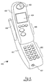
- the mobile telephone 100 of Fig. 1 comprises a body part 101 and a microphone arm 102 which is rotatably mounted to one comer of the body part. In the operational position shown in Fig. 1 the distance between the loudspeaker 103 at the top of the body part and the microphone 104 at the distant end of the microphone arm approximates the distance between the ear and mouth of a typical human user.
- FIG. 2 comprises a body part 201 and a hinged flip cover 202 which in a transport position covers a keypad 203 and in the operational position shown in Fig. 2 brings the microphone 204 at the distant end thereof far enough from a loudspeaker 205 in the body part.
- the mobile telephone 300 in Fig. 3 resembles functionally that 200 of Fig. 2, but the cover part 302 slides on a pair of sliding rails with respect to the body part 301 instead of rotating around a hinge.
- Keypad 303, microphone 304 and loudspeaker 305 serve same functions as in Fig. 2.
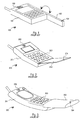
- Fig. 4 illustrates a mobile telephone 400 which comprises a lower body part 401 and an upper body part 402.
- the latter houses a loudspeaker 403, a display 404 and a limited number of keys in a quickfire keypad 405.
- the lower part houses a full (alpha)numerical keypad 406, a microphone 407 and an antenna 408.
- An exemplary structure of this kind is known e.g. from the Finnish registrated design application number 285/97.
- Figs 5a and 5b illustrate another known telescopic structure for a mobile telephone which differs from that of Fig. 4 in the mutual arrangement of the functional components.
- the telephone consists of an upper part 501 and a lower part of which the upper part houses an integral antenna 503, a radio transceiver 504, a loudspeaker 505, a display 506, a smart card reader 507 and a small keypad 508.
- the lower part comprises an extended keypad 509, a battery pack 510 and a charging connector 512 for coupling the telephone to a battery charger (not shown).
- the microphone 511 is located in the upper part, but it could also be in the lower part.
- the structure of Figs. 5a and 5b is known e.g. from the European patent publication number EP 0 944 219.
- a still further prior art extendable structure for a portable telephone is known from the European patent publication number EP 0 414 365.
- the structure comprises a housing having a main body and an extending sleeve-like portion mounted for longitudinal slidable movement between a retracted position when not in use and an extended position for use.
- the earphone is present in the main body and the microphone is in the extending portion.
- the telephone includes a plurality of buttons or keys which can be selectively actuated for operating the telephone.
- the extending portion is adapted to conceal selected ones of the buttons or keys when it is in the closed position to prevent accidental actuation of these buttons or keys.
- the objects of the invention are achieved by providing a body part and a grip part where the grip part has a sleeve-like form, is mounted for longitudinal slidable movement with respect to the body part and is extensive enough for a user to hold the telephone apparatus firmly by the grip part.
- the objects of the invention are further achieved by properly selecting and locating the parts that control the longitudinal movement of the grip part.
- a telephone apparatus comprises
- the releasing actuator is located within the grip part.
- sleeve-like is taken to describe an essentially tubular part designed to fit over another part.
- a body part which houses a majority of the functional components of the telephone apparatus, and a sleeve-like grip part which is mounted for longitudinal slidable movement with respect to the body part.
- a certain relatively large portion of the body part is inside the grip part.
- the body part may be even completely inside the grip part, or a certain portion of the body part may protrude out from one end of the grip part.
- Extending the telephone apparatus means moving the body part in a longitudinal direction thereof so that a relatively large portion comes out from the sleeve-like grip part.
- Retracting the telephone apparatus means moving the body part in the opposite longitudinal direction so that it arrives and locks back into the retracted configuration.
- a movement-effecting mechanism with a locking arrangement.
- a releasing switch for the locking arrangement is located in the grip part, preferably at a location where a finger of a human user naturally rests when the user grasps the telephone apparatus for holding it in a normal operational position. A simple actuation of the releasing switch releases the locking mechanism so that the movement-effecting mechanism is free to move the body part partially out of the grip part into the extended configuration.
- the movement-effecting mechanism is typically a spring-loaded mechanism preferably built around either a torsion spring or a clockwork spring.
- a torsion spring In the torsion spring based embodiments one end of the torsion spring is mechanically coupled to the body part and another end thereof is mechanically coupled to the grip part. In the retracted configuration the torsion spring is in an excited state so that a springback force tries to push the body part out of the grip part into the extended configuration.
- the grip part comprises a closed end and the torsion spring is located inside the grip part near the closed end, it is hidden from the eyes of users and protected from environmental hazards such as fouling and corrosion.
- the spring is preferably encapsulated into an enclosure which constitutes a part of either the body part or the grip part.
- One end of the spring is mechanically coupled to a gear wheel which engages with a mechanical gear arrangement between the body part and the grip part. Again in the retracted configuration the spring is in an excited state so that a springback force tries to rotate the gear wheel.
- the mechanical gear arrangement transforms the rotational movements of the gear wheel into longitudinal movements of the body part in relation to the grip part.
- spring-loaded movement-effecting mechanisms comprise e.g. motorized mechanisms where an electric motor generates the relative sliding movement between the grip part and the body part. If the electric motor has the characteristic feature of providing a large static torsional force that keeps the axle of the motor from rotating when not intentionally operated, the motor itself may be used as the locking mechanism in which case the releasing switch is just the on/off switch for the motor. Also such electrical motors exist where an integrated brake arrangement provides the mentioned static torsional force, in which case the releasing switch is both the releasing switch for the brake arrangement and the switch-on switch for the rotational movement of the motor. A motor can naturally be used in association with such a completely mechanical, separate locking arrangement which was described above in the context of spring-loaded movement-effecting mechanisms.
- magnets Another alternative for the movement-effecting mechanism is the use of magnets. If one wishes to use a magnetic force to effect a similar unidirectional loading as in the spring-loaded embodiments, it suffices to place a first magnet in the grip part and a second magnet in the body part so that in the retracted configuration the similarly named magnetic poles of the first and second magnets face each other at a close distance.
- the magnets may be permanent magnets, or at least one of them may be an electromagnet.
- a telephone apparatus From the viewpoint of the electrical operation of a telephone apparatus it is advantageous to place some functional components also into the grip part.
- Such components comprise microphones and connectors for providing an electric interface to auxiliary devices.
- An advantageous way of realizing the necessary electric interconnections between the body part and the grip part is to use a so-called flex or flexible printed circuit board where a number of conductors run on the surface of a thin dielectric foil.
- One part of the flex is attached to the grip part and another part of the flex is attached to the body part. Between the attached parts there is a portion of the flex which is not attached to anywhere and which is long enough in one direction to allow the body part and grip part to move between the retracted configuration and the extended configuration.
- the sleeve-like form of the grip part serves to hide the flex from the eyes of users as well as from potential environmental hazards.
- the longitudinal movement of the body part and grip part between the retracted and extended configurations is preferably further controlled by a mechanical damper which absorbs a part of the spring power in order to prevent the body part from clashing abruptly and loudly into the extended position. Damping the movement serves to lessen the mechanical stress and wear to the components. Additionally it helps to create an elegant overall appearance for the telephone apparatus.
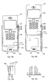
- Fig. 6a illustrates schematically a telephone device according to an advantageous embodiment of the invention in a retracted configuration where a relatively large portion of a body part 601 is within a sleeve-like grip part 602.
- Fig. 6b illustrates the same telephone device in an extended configuration where the body part has been moved into a longitudinal direction (upwards in the orientation shown in the drawings) so that a larger portion thereof has come out from the grip part.
- Fig. 6b shows the exemplary locations of a loudspeaker 603, a display 604 and a keypad 605 within the body part, and the exemplary locations of a locking mechanism release button 606 and a microphone 607 within the grip part.
- the sleeve-like grip part 602 is generally limited by front and back surfaces, two parallel side surfaces and a bottom surface.
- the front surface is the one which covers the keypad 605 in the retracted configuration
- the back surface is the one which is parallel to the front surface and not visible in Figs. 6a and 6b.
- the two side surfaces are those mutually parallel surfaces which are essentially perpendicular to the front and back surfaces; in Figs. 6a and 6b the locking mechanism release button 606 is located on one of the side surfaces.
- the bottom surface is the one which is perpendicular to the front, back and side surfaces and not visible in Figs. 6a and 6b.
- the location of the loudspeaker 603 and microphone 607 dictates that a normal operational position of the telephone apparatus in the extended configuration of Fig. 6b is such where the front surface of the grip part 602 is against the cheek of a user and the top end of the telephone apparatus points up and backwards.
- a human user grasps the telephone apparatus by the grip part with one hand so that one side surface rests against the thumb and palm. Simultaneously the tips of the other fingers rest on the other side surface.
- the location of the locking mechanism release button 606 which is shown in Figs.
- 6a and 6b is especially advantageous, since regardless of whether the user likes to hold the telephone apparatus in his right or left hand, the release button is always very conveniently placed in order for immediate actuation either with the thumb or with one of the other fingers. The user never has to use more than one hand to release the locking mechanism, and he may actuate the release button even without changing the natural position of the fingers of that hand.
- the body part 601 comprises a recess
- the release button 606 is mechanically coupled to a spring-loaded protrusion which fits into the recess when the telephone apparatus is in its retracted configuration and the release button is not pressed. Pressing the release button counteracts the spring-loading and causes the protrusion to retract from the recess.
- the body part may comprise another recess lower down near the end which is inside the grip part if the same locking mechanism is to be used to lock the telephone apparatus also into the extended position.
- Figs. 6a and 6b only disclose a single release button on one side of the grip part.
- the releasing mechanism may as well be constructed so that it comprises at least two release buttons. If exactly two release buttons are used, it is advantageous to place them on approximately the same level in the vertical direction shown in Figs. 6a and 6b but on opposite side surfaces of the grip part. If we continue with the assumption of a typical grasping hold used by a human user, placing one release button on each side surface would bring one of the release buttons within easy reach of the thumb and the other release button within easy reach of the tips of the other fingers. Additionally the most natural squeezing action of the holding hand is enough for actuating the release buttons.
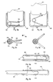
- Fig. 7 illustrates a torsion spring 700 which consists of a helically wound part 701 the ends of which extend to form two torsion arms 702 and 703.
- the torsion spring 700 is made by bending from a piece of spring steel wire or other suitably resilient material.
- Figs. 8a and 8b show how this kind of a spring may be used to provide the spring force which pushes a telephone apparatus according to an embodiment of the invention from the retracted configuration (Fig. 8a) to the extended configuration (Fig. 8b).
- Figs. 8a and 8b are partial cut-out diagrams where the bottom parts of the body part 601 and grip part 602 are shown.
- the torsion spring 700 is located at the closed bottom end of the grip part 602 so that one torsion arm 702 is mechanically coupled to the body part 601 and the other torsion arm 703 is mechanically coupled to the grip part 602.
- the torsion spring 700 In the retracted configuration of Fig. 8a the torsion spring 700 is in an excited state where the spring force resulting from the resiliency of the spring tends to widen the angle between the torsion arms. If the body part 601 is left free to move with respect to the grip part 602, said spring force pushes it upwards (taken the orientation shown in the drawings) until it reaches the extended configuration of Fig. 8b. In the extended configuration the torsion spring 700 is either in a relaxed state or at least in a much less excited state than in the retracted configuration.
- Figs. 8c and 8d show how a spiral spring module 800 can be used instead of a torsion spring as the structural unit which provides the spring force that causes the relative movement of the body part and the grip part.
- the spiral spring module 800 comprises a spiral spring 801 as well as a first reaction arm 802 and a second reaction arm 803.
- One end of the first reaction arm 802 expands to form a cylindrical housing 804 which encloses the spiral spring 801 therein.
- One end (the outer end in the embodiment of Figs 8c and 8d) of the spiral spring 801 is attached to the wall of the cylindrical housing 804 at point 805.
- One end of the second reaction arm 803 expands to form a circular lid which closes one end of the cylindrical housing 804.
- a central pin 806 extends from the circular lid to the inside of the cylindrical housing 804.
- the other end (the inner end in the embodiment of Figs 8c and 8d) of the spiral spring 801 is attached to the central pin 806.
- Fig. 8c corresponds to the retracted configuration.
- the angle between the reaction arms 802 and 803 is relatively large, and the spiral spring 801 is either in a relaxed state or at least in a much less excited state than in the retracted configuration.
- the ends of the first and second reaction arms which are distant from the spring housing can be mechanically coupled to the body part and the grip part respectively, exactly like the first and second torsion arms of the torsion spring described above.
- Figs. 9a and 9b illustrate a way of arranging for an electric connection between a sleeve-like grip part 602 and a body part 601.
- a flexible flat cable or flexible printed circuit board 901 typically called the flex for short, interconnects the grip part 602 and the body part 601 so that a certain first spot 902 of the flex is attached to the grip part 602 and a certain second spot 903 of the flex is attached to the body part 601.
- Between said first and second spots there is a free part 904 of the flex which is elongated in the direction coincident with the movement of the body part and not attached to anywhere.
- the free part of the flex is bent to form a 180 degrees curved section 905. In the retracted configuration of Fig.
- the coned section 905 is close to the bottom of the grip part 602 and a relatively large portion of the free part lies flat against the inner surface of the grip part between the first spot 902 and the curved section 905.
- the body part 601 moves into the extended configuration of Fig. 9b it draws the free part of the flex after it so that in the extended configuration the curved section starts almost immediately from the first spot 902 and most of the free part extends flatly between the curved section 905 and the second spot 903.
- Figs. 10a and 10b show a telephone apparatus according to an embodiment of the invention where the above-described features are all implemented.
- the telephone apparatus consists of a body part 601 and a sleeve-like grip part 602 a cutout of which is shown here to reveal certain structures therein.
- the shell or outer cover of the grip part may well consist of a front half and a back half so that Figs. 10a and 10b correspond to such a structure with the front half of the shell temporarily removed.
- Fig. 10a shows the telephone apparatus in a retracted configuration and Fig. 10b shows it in an extended configuration.
- the grip part 601 comprises at the bottom thereof a connector 1001 for providing an electromechanical interface between the telephone apparatus and potential auxiliary devices. Likewise at the bottom of the grip part there is a microphone 1002.
- the electrical connections between the functional components of the body part 601 and said connector 1001 and microphone 1002 go through a P-shaped flex 901 where the lower end of the loop in the P is separated from the stem of the P.
- the connector 1001 and microphone 1002 are connected to said lower end of the loop in the P; in the arrangement shown here the microphone 1002 is "piggy-backed" on top of the connector 1001 so that the microphone may be either directly connected to the flex 901 or there may be specific connecting arrangements in the connector 1001 which implement the coupling between the microphone 1002 and the flex 901.
- the loop of the P in the P-shaped flex 901 is attached to the inner surface of the grip part 602 e.g. by glueing.
- the stem of the P constitutes the free part of the flex 901 so that the upper end thereof is attached to the grip part 602 and the lower end is bent 180 degrees upwards and attached to the body part 601.
- the torsion spring 700 is located at the bottom of the grip part 602 in the essentially closed space left free under the bottom of the body part 601.
- the first torsion arm 702 is attached to the body part 601 and the second torsion arm 703 is bent so that it negotiates its way around the connector 1001 and is attached to the grip part 602.
- the grip part 602. Despite of the limited space available at the bottom of the grip part it is important to have rather long torsion arms in the torsion spring 700 in order to enable a long enough movement for the body part 601.
- the attachment of the first torsion arm 702 to the body part 601 is worth some consideration.
- An advantageous principle for the overall mechanical structure of the body part is such where a certain core or inner support structure forms the basis onto which the other main structural components like printed circuit board(s) and outer covers are attached.
- the core is a generally flat component lying parallel with the front and back surfaces of the body part and extending through the body part essentially along the central plane thereof.
- the surface of the core onto which a printed circuit board is to be attached may comprise elevated ridges that define separate compartments for certain components on that side of the board which comes against the core. If the core or at least the inner surfaces of said compartments are made electrically conductive, the core serves simultaneously as the electromagnetic interference shield for those components. Because the core has such a central role as a support structure, it is advantageous that the first torsion arm 702 is mechanically coupled directly to the core, i.e. the core comprises an attachment point 1003 for the end of the first torsion arm 702.
- the attachment point for the second torsion arm 703 is shown in Figs. 10a and 10b to consist of a moulded part of the inside of the grip part 602. In order to save space at the bottom of the grip part it may be advantageous to implement the attachment point for the second torsion arm 703 in some other way, e.g. by providing an attachment point at one part of the connector 1001.
- Figs. 10a and 10b also show an exemplary embodiment for the one-sided releasing switch.
- a pivoted lever 1004 one end of which constitutes the visible and actuatable release key 1005 while the other end 1006 protrudes into the inside of the grip part.
- said other end locks into a first recess 1007 in the body part 601, thus preventing the torsion spring 700 from ejecting the body part into the extended configuration.
- Pressing the release key end 1005 of the pivoted lever 1004 lifts the protruding end 1006 from the recess 1007, allowing free longitudinal movement of the body part 601.
- the protruding end 1006 locks into a second recess 1008 in the body part 601. If two releasing switch should be used, it is easy to arrange for a similar lever and recess arrangement on the other side of the telephone apparatus.
- Fig. 11a is an exploded view of a simple mechanical damper
- Fig. 11b illustrates the same mechanical damper in assembled configuration.
- the damper structure consists of a gear wheel 1101, an axle 1102, an O-ring 1103, a housing 1104, a rotor 1105 and a cap 1106.
- the gear wheel 1101 and the rotor 1105 are non-rotatably attached to opposite ends of the axle 1102.
- the axle may comprise portions with a non-circular (e.g. square) cross-section at its ends to facilitate the non-rotatable attachment.
- the axle 1102 goes through a central hole in one end face of the housing 1104 so that the rotor 1105 is located on the concave side of the housing 1104.
- the O-ring 1103 seals said central hole against essentially all leakage.
- the concave side of the housing 1104 defines an enclosure which is filled with a viscous damper fluid.
- damper fluids Various kinds of damper fluids are known, including such the viscosity of which is a function of a magnetic field. The invention does not limit the selection of the damper fluid.
- the operation of the damper of Figs. 11a and 11b is based on the simple fact that when the gear wheel 1101, axle 1102 and rotor 1105 rotate together, the friction caused by the damper fluid tends to slow down the rotational movement.
- a clockwork spring can be integrated to form a common structure with a damper which is generally of the type described above.
- Figs. 12a and 12b illustrate a combined spring and damper structure where, in addition to the gear wheel 1101 and rotor 1105, the axle 1202 is mechanically coupled to the inner end of a clockwork spring 1203.
- a clockwork spring is a spirally wound piece of spring steel wire or other suitably resilient material.
- a front cap 1204 and the walls of a doubly concave housing 1205 enclose the middle part of the axle 1202 together with the clockwork spring 1203 into an enclosure.
- the outer end of the clockwork spring 1203 is attached to a point of the walls of said enclosure.
- the O-ring 1103, rotor 1105 and rear cap 1106 as well as the concave rear side of the housing 1205 serve similar functions as in Figs. 11a and 11b.
- Directional terms like “front” and “rear” are only meant to refer schematically to the drawings and they do not limit the manufacture or use of any of the disclosed structures.
- Figs. 13a and 13b illustrate a variation of the structure of Figs. 12a and 12b.
- the front side of the housing 1303 is concave, there is only the front cap 1204, and both the clockwork spring 1203 and the rotor 1105 are enclosed in the common enclosure defined by the walls of the housing 1303 and the front cap 1204.
- a front O-ring 1301 seals the hole in the front cap 1204.
- both the clockwork spring 1203 and the rotor 1105 will be immersed in the damper fluid. If the damping of the longitudinal movement is not regarded as necessary, like e.g. in a low-end version of the extendable telephone apparatus product, it is possible to simplify the structure of Figs. 13a and 13b by leaving out the damper rotor 1105, the O-ring 1301 and the damper fluid.
- the friction caused by the damper fluid may even be large enough for implementing the damper arrangement as in Figs. 13c and 13d.
- the structure is otherwise similar to that in Figs. 13a and 13b, but there is no damper rotor.
- the clockwork spring 1203 will be immersed in the damper fluid and fulfil also the tasks of the rotor.
- Figs. 14a and 14b show how a combined clockwork spring and damper arrangement can be used to implement both the effecting and damping of the longitudinal movement of the body part 601 in relation to the grip part 602 between the retracted and extended configurations.
- a housing 1401 is located within the body part near the lower end thereof; the housing is of the type 1205 or 1303 shown in Figs. 12a and 12b, 13a and 13b or 13c and 13d so that it comprises therein both a damper rotor and a clockwork spring arrangement (not shown in Figs. 14a and 14b).
- a gear wheel 1101 is mechanically coupled to the damper rotor and clockwork spring arrangement.
- the housing and gear wheel may be at least partly hidden inside the outer cover of the body part 601 and correspondingly are drawn with dashed outline.
- a cogged rack 1402 is attached to the inside of the grip part 602 so that it lies parallel to the direction of the longitudinal movement of the body part 601 in relation to the grip part 602 between the retracted and extended configurations.
- the placement of the housing 1401 and gear wheel 1101 within the body part is such that the teeth of the gear wheel 1101 engage with those of the cogged rack 1402.
- the attaching of the ends of the clockwork spring inside the housing 1401 is made so that in the retracted position of Fig. 14a the spring is wound into an excited state. When the locking arrangement consisting of parts 1004, 1005, 1006 and 1007 is released, the spring starts unwinding.
- Figs. 14a and 14b functions otherwise in a manner equal to that described above but without the smoothing of the longitudinal movement.
- FIGs. 14a and 14b Only one combined clockwork spring and damper arrangement is shown in Figs. 14a and 14b to implement the effecting and damping of the longitudinal movement of the body part 601 in relation to the grip part 602 between the retracted and extended configurations.
- one clockwork spring and damper arrangement with their associated cogged racks is located on each side of the structure consisting of the body part and the grip part.
- Figs. 15a and 15b illustrate a hybrid arrangement where the body part 601 again comprises a housing 1104, but this time the housing only comprises a damper rotor immersed in a viscous damper fluid (not shown).
- the housing 1104 is generally of the type shown in Figs. 11a and 11b.
- gear wheel 1101 which is mechanically coupled to the damper rotor
- cogged rack 1402 which constitutes a part of the grip part 602 and is mechanically engaged with the gear wheel 1101.
- the purpose of the damper, gear wheel and cogged rack arrangement is only to damp the longitudinal movement of the body part 601 in relation to the grip part 602 between the retracted and extended configurations.
- the spring force for the effecting of the movement comes from a torsion spring 700 as in the embodiment of Figs. 10a and 10b.
- Figs. 16a and 16b illustrate an advantageous way of securing the engagement of a gear wheel 1101 with a cogged rack 1402.
- the cogged rack 1402 comprises a pair of longitudinal grooves 1601 along its sides. Attached to the housing which here consists of a spring barrel 1602 and a damper chamber 1603 (in a different mutual order than in the alternative arrangements described before) there are an outer sliding support 1604 and an inner sliding support 1605 the ends of which extend into said grooves.
- the sliding supports 1604 and 1605 slide in the grooves 1601 but prevent any vertical or transversal movements of the gear wheel which could cause slipping. If the transversal movements of the gear wheel can be eliminated to an adequate extent with e.g. making the other parts of the extending mechanism sturdy enough, it is possible to use only one groove and only one sliding support to eliminate vertical movements.
- Figs. 17a and 17b illustrate an alternative arrangement where the cogged rack 1402 need not to comprise any grooves. Instead of any outer and inner sliding supports there is a cradle 1701 attached to the housing.
- the cradle 1701 goes under the rack 1402 and comprises inner and outer edges that together define a groove where the rack may slide back and forth when the gear wheel rotates. The edges of this groove again prevent any vertical or transversal movements of the gear wheel 1101 in relation to the rack 1402.
- Figs. 16a to 17b may be simplified by removing the damper chamber 1603 altogether.
- the mechanical implementation of the rack 1402 deserves some further consideration.
- the placement of the rack on one hand and the damper, spring and gear wheel on the other hand is such that the rack constitutes a part of the grip part and the damper, spring and gear wheel arrangement (or only the damper and gear wheel arrangement, or only the spring and gear wheel arrangement) is located within the body part.
- This is advantageous e.g. from an aesthetical viewpoint, because the rack 1402 is relatively long in the direction of movement between the retracted configuration and the extended configuration, so placing it into the body part would almost inevitably result in part of the rack becoming visible to the user in the extended configuration.
- the invention is not limiting in this respect: the roles of the body part and the grip part in relation to the rack and damper, spring and gear wheel arrangement may well be exchanged.
- the rack is a part of the grip part it is advantageous from the manufacturing viewpoint if manufacturing the rack and attaching it to the grip part require as little extra steps in manufacturing as possible. If the grip part or an inner part thereof is made of plastics by injection moulding, it is possible to make the rack to appear in the mould so that the rack is produced simultaneously with the rest of the structure with no extra work required at all.
Landscapes
- Engineering & Computer Science (AREA)
- Signal Processing (AREA)
- Telephone Set Structure (AREA)
- Details Of Aerials (AREA)
Applications Claiming Priority (2)
| Application Number | Priority Date | Filing Date | Title |
|---|---|---|---|
| FI20001008 | 2000-04-28 | ||
| FI20001008A FI112422B (fi) | 2000-04-28 | 2000-04-28 | Teleskooppirakenne puhelinlaitetta varten |
Publications (3)
| Publication Number | Publication Date |
|---|---|
| EP1150476A2 true EP1150476A2 (de) | 2001-10-31 |
| EP1150476A3 EP1150476A3 (de) | 2003-08-27 |
| EP1150476B1 EP1150476B1 (de) | 2005-01-05 |
Family
ID=8558309
Family Applications (1)
| Application Number | Title | Priority Date | Filing Date |
|---|---|---|---|
| EP01660054A Expired - Lifetime EP1150476B1 (de) | 2000-04-28 | 2001-03-23 | Teleskopische Struktur für ein Telefonapparat |
Country Status (6)
| Country | Link |
|---|---|
| US (2) | US7231039B2 (de) |
| EP (1) | EP1150476B1 (de) |
| AT (1) | ATE286642T1 (de) |
| DE (1) | DE60108194T2 (de) |
| ES (1) | ES2234795T3 (de) |
| FI (1) | FI112422B (de) |
Cited By (32)
| Publication number | Priority date | Publication date | Assignee | Title |
|---|---|---|---|---|
| WO2002088568A1 (en) * | 2001-04-27 | 2002-11-07 | Nokia Corporation | Spring barrel module |
| WO2002089548A1 (en) * | 2001-04-27 | 2002-11-07 | Nokia Corporation | Extendable device |
| WO2003053026A2 (en) * | 2001-12-17 | 2003-06-26 | British Telecommunications Public Limited Company | Modular mobile telephone apparatus |
| EP1422911A2 (de) * | 2002-11-19 | 2004-05-26 | Samsung Electronics Co., Ltd. | Verschiebbares und tragbares Mobiltelefon |
| WO2004054317A1 (de) * | 2002-12-12 | 2004-06-24 | Siemens Aktiengesellschaft | Slider-mobiltelefon mit biegewellenlautsprecher |
| EP1496674A3 (de) * | 2003-07-11 | 2005-04-06 | Lg Electronics Inc. | Verschiebbares und tragbares Endgerät |
| EP1524820A2 (de) * | 2003-10-13 | 2005-04-20 | Hanbit Precision Co., Ltd. | Vorrichtung zum Öffnen und Schliessen des Deckels eines Mobiltelefons |
| WO2006041270A1 (en) * | 2004-10-15 | 2006-04-20 | Khvatec Co., Ltd. | Opening and closing mechanism for a mobile terminal |
| EP1638298A3 (de) * | 2004-09-16 | 2006-05-17 | Sony Ericsson Mobile Communications Japan, Inc. | Mobiles Endgerät mit einer automatischen Schiebevorrichtung |
| WO2006075838A1 (en) * | 2005-01-14 | 2006-07-20 | Shell-Line Co., Ltd. | Sliding hinge device, personal portable device having the sliding hinge device and method of manufacturing the sliding hinge device |
| WO2006075837A1 (en) | 2005-01-14 | 2006-07-20 | Shell-Line Co., Ltd. | Sliding hinge device, personal portable device having the sliding hinge device and method of manufacturing the sliding hinge device |
| WO2006075871A1 (en) * | 2005-01-11 | 2006-07-20 | Phoenix Korea Co., Ltd. | Portable device having two units rotating or sliding each other and coupling device for use in the same |
| WO2006083079A1 (en) * | 2005-02-02 | 2006-08-10 | Choi, Suck You | Sliding assembly for sliding-type mobile phones |
| WO2006107129A1 (en) * | 2005-04-08 | 2006-10-12 | Shell-Line Co., Ltd. | Sliding hinge device, personal portable device having the sliding hinge device and method of manufacturing the sliding hinge device |
| EP1742448A1 (de) | 2005-07-07 | 2007-01-10 | LG Electronics Inc. | Verschiebbares mobiles Endgerät mit Dämpfungseinheit |
| WO2007014041A1 (en) * | 2005-07-22 | 2007-02-01 | Zeetoo, Inc. | An apparatus for stabilizing an electronic device during data input and device control |
| WO2007065130A1 (en) * | 2005-12-01 | 2007-06-07 | Agere Systems Inc. | Apparatus and method for preventing an unintentional activation of a mobile communication device |
| CN100346623C (zh) * | 2003-01-29 | 2007-10-31 | 加藤电机株式会社 | 滑动机构以及使用这种滑动机构的移动电话机 |
| EP1860848A1 (de) * | 2006-05-24 | 2007-11-28 | Nokia Corporation | Schiebemechanismus für eine elektronische Vorrichtung mit einer magnetischen Ausrichtungsanordnung und einem Betätigungsmechanismus, das gegen der Ausrichtungsanordnung arbeitet |
| US7363065B2 (en) | 2004-04-30 | 2008-04-22 | Samsung Electro-Mechanics Co., Ltd. | Automatic sliding-type mobile communication terminal, method of automatically driving sliding-type mobile communication terminal, and method of detecting incoming call to sliding-type mobile communication terminal |
| EP1914963A1 (de) | 2006-10-17 | 2008-04-23 | Samsung Electronics Co., Ltd. | Mehrfach Drehfeder und halbautomatische Schiebevorrichtung damit |
| EP1936925A1 (de) | 2006-12-21 | 2008-06-25 | Sharp Kabushiki Kaisha | Verbundspulenfeder und damit ausgerüstetes mobiles Endgerät mit Gleitmechanismus |
| CN100452806C (zh) * | 2005-06-10 | 2009-01-14 | 乐金电子(中国)研究开发中心有限公司 | 一种天线露出型滑盖手机开关装置 |
| EP2065784A2 (de) * | 2007-11-28 | 2009-06-03 | ASUSTeK Computer Inc. | Tastatur |
| EP2166736A1 (de) * | 2008-09-19 | 2010-03-24 | LG Electronics Inc. | Gleitmodul und tragbares Endgerät damit |
| CN1761269B (zh) * | 2004-10-13 | 2010-05-05 | 株式会社卡西欧日立移动通信 | 具有滑行机构的携带式信息终端 |
| WO2010089298A1 (en) * | 2009-02-05 | 2010-08-12 | Nokia Corporation | Magnetic actuation mechanism |
| WO2010099834A1 (en) * | 2009-03-03 | 2010-09-10 | Sony Ericsson Mobile Communications Ab | Mechanism for radio communication terminal |
| US8104979B2 (en) | 2007-11-28 | 2012-01-31 | Asustek Computer Inc. | Keyboard with keystroke module movably disposed to an opening |
| EP2472831A1 (de) * | 2009-08-26 | 2012-07-04 | Andrey Vyacheslavovich Agarkov | Mobiltelefon |
| WO2013102687A1 (es) * | 2012-01-03 | 2013-07-11 | Barba Carujo Enrique | Funda de teléfono móvil con medios de extraccion del mismo |
| US9250651B2 (en) | 2013-04-24 | 2016-02-02 | Google Technology Holdings LLC | Electronic device with folded display |
Families Citing this family (23)
| Publication number | Priority date | Publication date | Assignee | Title |
|---|---|---|---|---|
| KR100421994B1 (ko) * | 2001-05-21 | 2004-03-10 | 삼성전자주식회사 | 촬상장치용 뷰파인더 및 이를 구비한 캠코더 |
| US6719358B2 (en) * | 2001-09-04 | 2004-04-13 | Lear Corporation | Control panel for a vehicle |
| US6961401B1 (en) * | 2003-06-26 | 2005-11-01 | Sportcraft, Ltd. | Retractable pedometer |
| EP1661257A1 (de) * | 2003-08-25 | 2006-05-31 | M2SYS Co., Ltd. | Schiebeöffnungs- und schliesseinrichtung und tragbares endgerät damit |
| JP2005311668A (ja) * | 2004-04-21 | 2005-11-04 | Hitachi Ltd | 開閉部を有する情報処理装置 |
| KR100834626B1 (ko) * | 2004-05-06 | 2008-06-02 | 삼성전자주식회사 | 자기 거치 기능을 구비한 슬라이딩/스윙 타입 휴대 장치 |
| KR100628120B1 (ko) * | 2004-08-18 | 2006-09-26 | 엘지전자 주식회사 | 슬라이드타입 이동통신 단말기의 스프링장치 |
| US20060046792A1 (en) * | 2004-08-31 | 2006-03-02 | Hassemer Brian J | Hinge apparatus and methods therefor |
| JP2006108881A (ja) * | 2004-10-01 | 2006-04-20 | Kato Electrical Mach Co Ltd | 携帯機器のスライド機構及び携帯電話機 |
| US7353053B2 (en) * | 2004-11-23 | 2008-04-01 | Oqo, Inc. | Non-binding sliding display for a handheld electronic device |
| US7520436B2 (en) * | 2005-04-18 | 2009-04-21 | Samsung Electronics Co., Ltd | Slide module for slide type portable terminal and cover apparatus for external type card mounted thereto |
| US7558057B1 (en) | 2005-06-06 | 2009-07-07 | Alex Naksen | Personal digital device with adjustable interface |
| US7627337B2 (en) * | 2006-04-17 | 2009-12-01 | Nokia Corporation | Dual lever slide mechanism for extendible device housings |
| KR100713479B1 (ko) * | 2006-06-08 | 2007-05-02 | 삼성전자주식회사 | 휴대 단말기 및 그의 슬라이딩/스윙 거치 장치 |
| KR100865491B1 (ko) * | 2006-07-07 | 2008-10-27 | 주식회사 피앤텔 | 토션 스프링, 탄성기구 및 이를 이용한 슬라이딩개폐장치와 휴대용 응용기기 |
| US7558396B2 (en) * | 2006-09-15 | 2009-07-07 | Fortemedia, Inc. | Microphone module at corner or edge of electronic device |
| WO2008103418A2 (en) * | 2007-02-22 | 2008-08-28 | Roy Sandberg | Method and apparatus for panning, tilting, and adjusting the height of a remotely controlled camera |
| US8121334B2 (en) * | 2007-06-18 | 2012-02-21 | Cal-Comp Electronics & Communications Company Limited | Bluetooth earphone having semi-automatic receiving function |
| US7959201B2 (en) * | 2008-07-29 | 2011-06-14 | Honda Motor Co., Ltd. | Gear damper |
| US8139367B2 (en) | 2008-09-25 | 2012-03-20 | Motorola Mobility, Inc. | Torsion spring mechanism supportive of a flexible printed circuit |
| JP5257199B2 (ja) * | 2009-03-30 | 2013-08-07 | 富士通株式会社 | 携帯機器 |
| US9307326B2 (en) * | 2009-12-22 | 2016-04-05 | Mh Acoustics Llc | Surface-mounted microphone arrays on flexible printed circuit boards |
| US8540062B2 (en) * | 2011-05-20 | 2013-09-24 | Research In Motion Limited | Low profile rotary damper |
Citations (9)
| Publication number | Priority date | Publication date | Assignee | Title |
|---|---|---|---|---|
| DE3542424A1 (de) * | 1985-11-30 | 1987-06-04 | Ackermann Albert Gmbh Co | Haltevorrichtung |
| EP0414365A2 (de) * | 1989-08-24 | 1991-02-27 | Nokia Mobile Phones (U.K.) Limited | Tragbares Funktelefon |
| EP0536578A2 (de) * | 1991-10-08 | 1993-04-14 | Siemens Aktiengesellschaft | Funktelefon |
| US5522485A (en) * | 1992-05-08 | 1996-06-04 | Nifco Inc. | Rotary damper |
| EP0792055A2 (de) * | 1996-02-26 | 1997-08-27 | Nokia Mobile Phones Ltd. | Funktelefon |
| WO1998009414A1 (en) * | 1996-08-29 | 1998-03-05 | Bellsouth Corporation | Portable radiotelephone with sliding cover and automatic antenna extension |
| DE29814228U1 (de) * | 1998-08-07 | 1999-01-28 | Siemens Ag | Mobilteil eines funkbetriebenen Kommunikationsendegerätes |
| WO1999043134A1 (en) * | 1998-02-17 | 1999-08-26 | Telefonaktiebolaget Lm Ericsson | Hinge assemblies for electronic devices |
| EP0944219A2 (de) * | 1998-03-18 | 1999-09-22 | Nokia Mobile Phones Ltd. | Teleskopisches Telefongerät |
Family Cites Families (4)
| Publication number | Priority date | Publication date | Assignee | Title |
|---|---|---|---|---|
| US5440629A (en) * | 1993-07-02 | 1995-08-08 | Gray; Robert R. | Changeable contour construction of wireless telephone |
| DE29623336U1 (de) | 1995-07-10 | 1998-06-18 | Peiker Andreas | Handfunktelefon |
| SE516165C2 (sv) * | 1999-02-18 | 2001-11-26 | Ericsson Telefon Ab L M | Portabel elektrisk apparat med en urkopplingsbar strömkälleenhet |
| US6249672B1 (en) * | 1999-03-19 | 2001-06-19 | Mobile Communications Holdings, Inc. | Portable telephone |
-
2000
- 2000-04-28 FI FI20001008A patent/FI112422B/fi not_active IP Right Cessation
-
2001
- 2001-03-23 ES ES01660054T patent/ES2234795T3/es not_active Expired - Lifetime
- 2001-03-23 AT AT01660054T patent/ATE286642T1/de not_active IP Right Cessation
- 2001-03-23 EP EP01660054A patent/EP1150476B1/de not_active Expired - Lifetime
- 2001-03-23 DE DE60108194T patent/DE60108194T2/de not_active Expired - Lifetime
- 2001-04-25 US US09/842,563 patent/US7231039B2/en not_active Expired - Fee Related
-
2006
- 2006-07-20 US US11/458,708 patent/US7636437B2/en not_active Expired - Fee Related
Patent Citations (9)
| Publication number | Priority date | Publication date | Assignee | Title |
|---|---|---|---|---|
| DE3542424A1 (de) * | 1985-11-30 | 1987-06-04 | Ackermann Albert Gmbh Co | Haltevorrichtung |
| EP0414365A2 (de) * | 1989-08-24 | 1991-02-27 | Nokia Mobile Phones (U.K.) Limited | Tragbares Funktelefon |
| EP0536578A2 (de) * | 1991-10-08 | 1993-04-14 | Siemens Aktiengesellschaft | Funktelefon |
| US5522485A (en) * | 1992-05-08 | 1996-06-04 | Nifco Inc. | Rotary damper |
| EP0792055A2 (de) * | 1996-02-26 | 1997-08-27 | Nokia Mobile Phones Ltd. | Funktelefon |
| WO1998009414A1 (en) * | 1996-08-29 | 1998-03-05 | Bellsouth Corporation | Portable radiotelephone with sliding cover and automatic antenna extension |
| WO1999043134A1 (en) * | 1998-02-17 | 1999-08-26 | Telefonaktiebolaget Lm Ericsson | Hinge assemblies for electronic devices |
| EP0944219A2 (de) * | 1998-03-18 | 1999-09-22 | Nokia Mobile Phones Ltd. | Teleskopisches Telefongerät |
| DE29814228U1 (de) * | 1998-08-07 | 1999-01-28 | Siemens Ag | Mobilteil eines funkbetriebenen Kommunikationsendegerätes |
Cited By (57)
| Publication number | Priority date | Publication date | Assignee | Title |
|---|---|---|---|---|
| GB2390662B (en) * | 2001-04-27 | 2004-10-06 | Nokia Corp | Spring barrel module |
| WO2002089548A1 (en) * | 2001-04-27 | 2002-11-07 | Nokia Corporation | Extendable device |
| GB2390662A (en) * | 2001-04-27 | 2004-01-14 | Nokia Corp | Spring barrel module |
| GB2391285A (en) * | 2001-04-27 | 2004-02-04 | Nokia Corp | Extendable device |
| US6733005B2 (en) | 2001-04-27 | 2004-05-11 | Nokia Corporation | Two-part device |
| JP2008035553A (ja) * | 2001-04-27 | 2008-02-14 | Nokia Corp | 2部分装置 |
| WO2002088568A1 (en) * | 2001-04-27 | 2002-11-07 | Nokia Corporation | Spring barrel module |
| GB2391285B (en) * | 2001-04-27 | 2004-10-06 | Nokia Corp | Extendable device |
| WO2003053026A2 (en) * | 2001-12-17 | 2003-06-26 | British Telecommunications Public Limited Company | Modular mobile telephone apparatus |
| WO2003053026A3 (en) * | 2001-12-17 | 2003-08-14 | British Telecomm | Modular mobile telephone apparatus |
| EP1422911A3 (de) * | 2002-11-19 | 2004-06-09 | Samsung Electronics Co., Ltd. | Verschiebbares und tragbares Mobiltelefon |
| US6822871B2 (en) | 2002-11-19 | 2004-11-23 | Samsung Electronics Co., Ltd. | Sliding-type portable wireless terminal |
| EP1422911A2 (de) * | 2002-11-19 | 2004-05-26 | Samsung Electronics Co., Ltd. | Verschiebbares und tragbares Mobiltelefon |
| WO2004054317A1 (de) * | 2002-12-12 | 2004-06-24 | Siemens Aktiengesellschaft | Slider-mobiltelefon mit biegewellenlautsprecher |
| US7590436B2 (en) | 2002-12-12 | 2009-09-15 | Palm, Inc. | Slider mobile telephone comprising a bending wave loudspeaker |
| CN100346623C (zh) * | 2003-01-29 | 2007-10-31 | 加藤电机株式会社 | 滑动机构以及使用这种滑动机构的移动电话机 |
| EP1496674A3 (de) * | 2003-07-11 | 2005-04-06 | Lg Electronics Inc. | Verschiebbares und tragbares Endgerät |
| US7363066B2 (en) | 2003-07-11 | 2008-04-22 | Lg Electronics Inc. | Slide type portable terminal |
| EP1524820A2 (de) * | 2003-10-13 | 2005-04-20 | Hanbit Precision Co., Ltd. | Vorrichtung zum Öffnen und Schliessen des Deckels eines Mobiltelefons |
| EP1524820A3 (de) * | 2003-10-13 | 2006-03-15 | Hanbit Precision Co., Ltd. | Vorrichtung zum Öffnen und Schliessen des Deckels eines Mobiltelefons |
| US7363065B2 (en) | 2004-04-30 | 2008-04-22 | Samsung Electro-Mechanics Co., Ltd. | Automatic sliding-type mobile communication terminal, method of automatically driving sliding-type mobile communication terminal, and method of detecting incoming call to sliding-type mobile communication terminal |
| US7599721B2 (en) | 2004-09-16 | 2009-10-06 | Sony Ericsson Mobile Communications Japan, Inc. | Mobile terminal device including an elevating keyboard mechanism |
| EP1638298A3 (de) * | 2004-09-16 | 2006-05-17 | Sony Ericsson Mobile Communications Japan, Inc. | Mobiles Endgerät mit einer automatischen Schiebevorrichtung |
| CN1761269B (zh) * | 2004-10-13 | 2010-05-05 | 株式会社卡西欧日立移动通信 | 具有滑行机构的携带式信息终端 |
| WO2006041270A1 (en) * | 2004-10-15 | 2006-04-20 | Khvatec Co., Ltd. | Opening and closing mechanism for a mobile terminal |
| WO2006075871A1 (en) * | 2005-01-11 | 2006-07-20 | Phoenix Korea Co., Ltd. | Portable device having two units rotating or sliding each other and coupling device for use in the same |
| WO2006075838A1 (en) * | 2005-01-14 | 2006-07-20 | Shell-Line Co., Ltd. | Sliding hinge device, personal portable device having the sliding hinge device and method of manufacturing the sliding hinge device |
| WO2006075837A1 (en) | 2005-01-14 | 2006-07-20 | Shell-Line Co., Ltd. | Sliding hinge device, personal portable device having the sliding hinge device and method of manufacturing the sliding hinge device |
| JP2008533389A (ja) * | 2005-01-14 | 2008-08-21 | シェル−ライン・カンパニー・リミテッド | スライドヒンジ装置、個人携帯端末機、ヒンジ装置の製造方法 |
| WO2006083079A1 (en) * | 2005-02-02 | 2006-08-10 | Choi, Suck You | Sliding assembly for sliding-type mobile phones |
| WO2006107129A1 (en) * | 2005-04-08 | 2006-10-12 | Shell-Line Co., Ltd. | Sliding hinge device, personal portable device having the sliding hinge device and method of manufacturing the sliding hinge device |
| CN100452806C (zh) * | 2005-06-10 | 2009-01-14 | 乐金电子(中国)研究开发中心有限公司 | 一种天线露出型滑盖手机开关装置 |
| EP1742448A1 (de) | 2005-07-07 | 2007-01-10 | LG Electronics Inc. | Verschiebbares mobiles Endgerät mit Dämpfungseinheit |
| WO2007014041A1 (en) * | 2005-07-22 | 2007-02-01 | Zeetoo, Inc. | An apparatus for stabilizing an electronic device during data input and device control |
| US7570978B2 (en) | 2005-12-01 | 2009-08-04 | Agere Systems Inc. | Apparatus and method for preventing an unintentional activation of a mobile communication device |
| WO2007065130A1 (en) * | 2005-12-01 | 2007-06-07 | Agere Systems Inc. | Apparatus and method for preventing an unintentional activation of a mobile communication device |
| EP1860848A1 (de) * | 2006-05-24 | 2007-11-28 | Nokia Corporation | Schiebemechanismus für eine elektronische Vorrichtung mit einer magnetischen Ausrichtungsanordnung und einem Betätigungsmechanismus, das gegen der Ausrichtungsanordnung arbeitet |
| US7515930B2 (en) | 2006-05-24 | 2009-04-07 | Nokia Corporation | Electronic device sliding mechanism |
| CN101106884B (zh) * | 2006-05-24 | 2010-06-09 | 诺基亚公司 | 电子设备的滑动机构 |
| EP1914963A1 (de) | 2006-10-17 | 2008-04-23 | Samsung Electronics Co., Ltd. | Mehrfach Drehfeder und halbautomatische Schiebevorrichtung damit |
| US7945299B2 (en) | 2006-10-17 | 2011-05-17 | Samsung Electronics Co., Ltd | Multiple torsion spring and semi-automatic sliding device using the same |
| EP1936925A1 (de) | 2006-12-21 | 2008-06-25 | Sharp Kabushiki Kaisha | Verbundspulenfeder und damit ausgerüstetes mobiles Endgerät mit Gleitmechanismus |
| US7941192B2 (en) | 2006-12-21 | 2011-05-10 | Sharp Kabushiki Kaisha | Torsion coil spring and sliding type mobile terminal equipped therewith |
| EP2065784A3 (de) * | 2007-11-28 | 2010-05-05 | ASUSTeK Computer Inc. | Tastatur |
| EP2065784A2 (de) * | 2007-11-28 | 2009-06-03 | ASUSTeK Computer Inc. | Tastatur |
| US8104979B2 (en) | 2007-11-28 | 2012-01-31 | Asustek Computer Inc. | Keyboard with keystroke module movably disposed to an opening |
| EP2166736A1 (de) * | 2008-09-19 | 2010-03-24 | LG Electronics Inc. | Gleitmodul und tragbares Endgerät damit |
| US8249669B2 (en) | 2008-09-19 | 2012-08-21 | Lg Electronics Inc. | Slide module and portable terminal having the same |
| WO2010089298A1 (en) * | 2009-02-05 | 2010-08-12 | Nokia Corporation | Magnetic actuation mechanism |
| WO2010099834A1 (en) * | 2009-03-03 | 2010-09-10 | Sony Ericsson Mobile Communications Ab | Mechanism for radio communication terminal |
| US8121661B2 (en) | 2009-03-03 | 2012-02-21 | Sony Ericsson Mobile Communications Ab | Mechanism for radio communication terminal |
| CN102342082A (zh) * | 2009-03-03 | 2012-02-01 | 索尼爱立信移动通讯有限公司 | 用于无线通信终端的机构 |
| CN102342082B (zh) * | 2009-03-03 | 2014-03-05 | 索尼爱立信移动通讯有限公司 | 用于无线通信终端的机构 |
| EP2472831A1 (de) * | 2009-08-26 | 2012-07-04 | Andrey Vyacheslavovich Agarkov | Mobiltelefon |
| EP2472831A4 (de) * | 2009-08-26 | 2014-05-28 | Andrey Vyacheslavovich Agarkov | Mobiltelefon |
| WO2013102687A1 (es) * | 2012-01-03 | 2013-07-11 | Barba Carujo Enrique | Funda de teléfono móvil con medios de extraccion del mismo |
| US9250651B2 (en) | 2013-04-24 | 2016-02-02 | Google Technology Holdings LLC | Electronic device with folded display |
Also Published As
| Publication number | Publication date |
|---|---|
| DE60108194T2 (de) | 2005-12-29 |
| FI112422B (fi) | 2003-11-28 |
| FI20001008A0 (fi) | 2000-04-28 |
| ES2234795T3 (es) | 2005-07-01 |
| US20060251244A1 (en) | 2006-11-09 |
| DE60108194D1 (de) | 2005-02-10 |
| US7231039B2 (en) | 2007-06-12 |
| EP1150476A3 (de) | 2003-08-27 |
| US7636437B2 (en) | 2009-12-22 |
| FI20001008A (fi) | 2001-10-29 |
| EP1150476B1 (de) | 2005-01-05 |
| US20010036266A1 (en) | 2001-11-01 |
| ATE286642T1 (de) | 2005-01-15 |
Similar Documents
| Publication | Publication Date | Title |
|---|---|---|
| EP1150476B1 (de) | Teleskopische Struktur für ein Telefonapparat | |
| EP0414365B1 (de) | Tragbares Funktelefon | |
| US5504813A (en) | Portable telephone | |
| JP2914923B2 (ja) | ポインティング・デバイスを有する小型電子機器 | |
| WO2012067029A1 (ja) | 電子機器保持具 | |
| EP1162711B1 (de) | Kombination aus einem Halter und einem Batterieladegerät | |
| EP1715661B1 (de) | Verschiebemodul eines verschiebbaren tragbaren Endgerätes und Abdeckvorrichtung dafür | |
| CN111988697B (zh) | 耳机充电盒 | |
| WO2009064323A1 (en) | Mobile terminal having a slidable keyboard and method for operating the same | |
| CN215732585U (zh) | 双向随意拉装置及双向随意拉数据线 | |
| CA2142722C (en) | A latching system | |
| JP2002029304A (ja) | 車両用物品保持装置 | |
| US20060137129A1 (en) | Vacuum cleaner provided with an auxiliary pull-out device for an electrical cable | |
| EP1111712A1 (de) | Antennenanordnung | |
| CN112203001A (zh) | 终端 | |
| KR200178343Y1 (ko) | 이어 마이크 세트 | |
| KR200218503Y1 (ko) | 슬라이딩 수납식 이동통신 단말기 | |
| CN216451498U (zh) | 一种具有无线充电功能的蓝牙音箱 | |
| JPH11136329A (ja) | 折り畳み型電子機器 | |
| CN216210550U (zh) | 中央控制装置 | |
| CN217309395U (zh) | 收纳盒 | |
| CN113810818B (zh) | 耳机组件 | |
| CN115942176A (zh) | 耳机盒及耳机套件 | |
| KR100335755B1 (ko) | 키보드-폰 | |
| JPH0621846A (ja) | アンテナ引出し装置 |
Legal Events
| Date | Code | Title | Description |
|---|---|---|---|
| PUAI | Public reference made under article 153(3) epc to a published international application that has entered the european phase |
Free format text: ORIGINAL CODE: 0009012 |
|
| AK | Designated contracting states |
Kind code of ref document: A2 Designated state(s): AT BE CH CY DE DK ES FI FR GB GR IE IT LI LU MC NL PT SE TR |
|
| AX | Request for extension of the european patent |
Free format text: AL;LT;LV;MK;RO;SI |
|
| RAP1 | Party data changed (applicant data changed or rights of an application transferred) |
Owner name: NOKIA CORPORATION |
|
| PUAL | Search report despatched |
Free format text: ORIGINAL CODE: 0009013 |
|
| AK | Designated contracting states |
Designated state(s): AT BE CH CY DE DK ES FI FR GB GR IE IT LI LU MC NL PT SE TR |
|
| AX | Request for extension of the european patent |
Extension state: AL LT LV MK RO SI |
|
| RIN1 | Information on inventor provided before grant (corrected) |
Inventor name: PERTTULA, AULIS Inventor name: ROENKKO, ANTTI Inventor name: SAVOLAINEN, PERTTI Inventor name: GROENROOS, MIKA Inventor name: SUUTARI, JARI Inventor name: KAUHANIEMI, ILPO |
|
| 17P | Request for examination filed |
Effective date: 20031030 |
|
| 17Q | First examination report despatched |
Effective date: 20040212 |
|
| AKX | Designation fees paid |
Designated state(s): AT BE CH CY DE DK ES FI FR GB GR IE IT LI LU MC NL PT SE TR |
|
| GRAP | Despatch of communication of intention to grant a patent |
Free format text: ORIGINAL CODE: EPIDOSNIGR1 |
|
| GRAS | Grant fee paid |
Free format text: ORIGINAL CODE: EPIDOSNIGR3 |
|
| GRAA | (expected) grant |
Free format text: ORIGINAL CODE: 0009210 |
|
| AK | Designated contracting states |
Kind code of ref document: B1 Designated state(s): AT BE CH CY DE DK ES FI FR GB GR IE IT LI LU MC NL PT SE TR |
|
| PG25 | Lapsed in a contracting state [announced via postgrant information from national office to epo] |
Ref country code: CH Free format text: LAPSE BECAUSE OF FAILURE TO SUBMIT A TRANSLATION OF THE DESCRIPTION OR TO PAY THE FEE WITHIN THE PRESCRIBED TIME-LIMIT Effective date: 20050105 Ref country code: LI Free format text: LAPSE BECAUSE OF FAILURE TO SUBMIT A TRANSLATION OF THE DESCRIPTION OR TO PAY THE FEE WITHIN THE PRESCRIBED TIME-LIMIT Effective date: 20050105 Ref country code: TR Free format text: LAPSE BECAUSE OF FAILURE TO SUBMIT A TRANSLATION OF THE DESCRIPTION OR TO PAY THE FEE WITHIN THE PRESCRIBED TIME-LIMIT Effective date: 20050105 Ref country code: BE Free format text: LAPSE BECAUSE OF FAILURE TO SUBMIT A TRANSLATION OF THE DESCRIPTION OR TO PAY THE FEE WITHIN THE PRESCRIBED TIME-LIMIT Effective date: 20050105 Ref country code: FI Free format text: LAPSE BECAUSE OF FAILURE TO SUBMIT A TRANSLATION OF THE DESCRIPTION OR TO PAY THE FEE WITHIN THE PRESCRIBED TIME-LIMIT Effective date: 20050105 Ref country code: AT Free format text: LAPSE BECAUSE OF FAILURE TO SUBMIT A TRANSLATION OF THE DESCRIPTION OR TO PAY THE FEE WITHIN THE PRESCRIBED TIME-LIMIT Effective date: 20050105 |
|
| REG | Reference to a national code |
Ref country code: GB Ref legal event code: FG4D |
|
| REG | Reference to a national code |
Ref country code: CH Ref legal event code: EP |
|
| REG | Reference to a national code |
Ref country code: IE Ref legal event code: FG4D |
|
| REF | Corresponds to: |
Ref document number: 60108194 Country of ref document: DE Date of ref document: 20050210 Kind code of ref document: P |
|
| PG25 | Lapsed in a contracting state [announced via postgrant information from national office to epo] |
Ref country code: CY Free format text: LAPSE BECAUSE OF FAILURE TO SUBMIT A TRANSLATION OF THE DESCRIPTION OR TO PAY THE FEE WITHIN THE PRESCRIBED TIME-LIMIT Effective date: 20050323 Ref country code: LU Free format text: LAPSE BECAUSE OF NON-PAYMENT OF DUE FEES Effective date: 20050323 Ref country code: IE Free format text: LAPSE BECAUSE OF NON-PAYMENT OF DUE FEES Effective date: 20050323 |
|
| PG25 | Lapsed in a contracting state [announced via postgrant information from national office to epo] |
Ref country code: MC Free format text: LAPSE BECAUSE OF NON-PAYMENT OF DUE FEES Effective date: 20050331 |
|
| PG25 | Lapsed in a contracting state [announced via postgrant information from national office to epo] |
Ref country code: GR Free format text: LAPSE BECAUSE OF FAILURE TO SUBMIT A TRANSLATION OF THE DESCRIPTION OR TO PAY THE FEE WITHIN THE PRESCRIBED TIME-LIMIT Effective date: 20050405 Ref country code: DK Free format text: LAPSE BECAUSE OF FAILURE TO SUBMIT A TRANSLATION OF THE DESCRIPTION OR TO PAY THE FEE WITHIN THE PRESCRIBED TIME-LIMIT Effective date: 20050405 |
|
| REG | Reference to a national code |
Ref country code: SE Ref legal event code: TRGR |
|
| REG | Reference to a national code |
Ref country code: ES Ref legal event code: FG2A Ref document number: 2234795 Country of ref document: ES Kind code of ref document: T3 |
|
| REG | Reference to a national code |
Ref country code: CH Ref legal event code: PL |
|
| ET | Fr: translation filed | ||
| PLBE | No opposition filed within time limit |
Free format text: ORIGINAL CODE: 0009261 |
|
| STAA | Information on the status of an ep patent application or granted ep patent |
Free format text: STATUS: NO OPPOSITION FILED WITHIN TIME LIMIT |
|
| 26N | No opposition filed |
Effective date: 20051006 |
|
| REG | Reference to a national code |
Ref country code: IE Ref legal event code: MM4A |
|
| REG | Reference to a national code |
Ref country code: GB Ref legal event code: FG4D |
|
| PG25 | Lapsed in a contracting state [announced via postgrant information from national office to epo] |
Ref country code: PT Free format text: LAPSE BECAUSE OF NON-PAYMENT OF DUE FEES Effective date: 20050605 |
|
| PGFP | Annual fee paid to national office [announced via postgrant information from national office to epo] |
Ref country code: FR Payment date: 20110317 Year of fee payment: 11 |
|
| PGFP | Annual fee paid to national office [announced via postgrant information from national office to epo] |
Ref country code: GB Payment date: 20110323 Year of fee payment: 11 |
|
| PGFP | Annual fee paid to national office [announced via postgrant information from national office to epo] |
Ref country code: IT Payment date: 20110325 Year of fee payment: 11 |
|
| GBPC | Gb: european patent ceased through non-payment of renewal fee |
Effective date: 20120323 |
|
| REG | Reference to a national code |
Ref country code: FR Ref legal event code: ST Effective date: 20121130 |
|
| PG25 | Lapsed in a contracting state [announced via postgrant information from national office to epo] |
Ref country code: FR Free format text: LAPSE BECAUSE OF NON-PAYMENT OF DUE FEES Effective date: 20120402 Ref country code: GB Free format text: LAPSE BECAUSE OF NON-PAYMENT OF DUE FEES Effective date: 20120323 |
|
| PG25 | Lapsed in a contracting state [announced via postgrant information from national office to epo] |
Ref country code: IT Free format text: LAPSE BECAUSE OF NON-PAYMENT OF DUE FEES Effective date: 20120323 |
|
| PGFP | Annual fee paid to national office [announced via postgrant information from national office to epo] |
Ref country code: SE Payment date: 20130312 Year of fee payment: 13 Ref country code: DE Payment date: 20130320 Year of fee payment: 13 Ref country code: ES Payment date: 20130312 Year of fee payment: 13 |
|
| PGFP | Annual fee paid to national office [announced via postgrant information from national office to epo] |
Ref country code: NL Payment date: 20130309 Year of fee payment: 13 |
|
| REG | Reference to a national code |
Ref country code: DE Ref legal event code: R119 Ref document number: 60108194 Country of ref document: DE |
|
| REG | Reference to a national code |
Ref country code: NL Ref legal event code: V1 Effective date: 20141001 |
|
| REG | Reference to a national code |
Ref country code: SE Ref legal event code: EUG |
|
| PG25 | Lapsed in a contracting state [announced via postgrant information from national office to epo] |
Ref country code: SE Free format text: LAPSE BECAUSE OF NON-PAYMENT OF DUE FEES Effective date: 20140324 |
|
| REG | Reference to a national code |
Ref country code: DE Ref legal event code: R119 Ref document number: 60108194 Country of ref document: DE Effective date: 20141001 |
|
| PG25 | Lapsed in a contracting state [announced via postgrant information from national office to epo] |
Ref country code: DE Free format text: LAPSE BECAUSE OF NON-PAYMENT OF DUE FEES Effective date: 20141001 |
|
| PG25 | Lapsed in a contracting state [announced via postgrant information from national office to epo] |
Ref country code: NL Free format text: LAPSE BECAUSE OF NON-PAYMENT OF DUE FEES Effective date: 20141001 |
|
| REG | Reference to a national code |
Ref country code: ES Ref legal event code: FD2A Effective date: 20150427 |
|
| PG25 | Lapsed in a contracting state [announced via postgrant information from national office to epo] |
Ref country code: ES Free format text: LAPSE BECAUSE OF NON-PAYMENT OF DUE FEES Effective date: 20140324 |