EP2065784A2 - Tastatur - Google Patents
Tastatur Download PDFInfo
- Publication number
- EP2065784A2 EP2065784A2 EP08167293A EP08167293A EP2065784A2 EP 2065784 A2 EP2065784 A2 EP 2065784A2 EP 08167293 A EP08167293 A EP 08167293A EP 08167293 A EP08167293 A EP 08167293A EP 2065784 A2 EP2065784 A2 EP 2065784A2
- Authority
- EP
- European Patent Office
- Prior art keywords
- housing
- magnetic elements
- keyboard
- keyboard according
- keystroke module
- Prior art date
- Legal status (The legal status is an assumption and is not a legal conclusion. Google has not performed a legal analysis and makes no representation as to the accuracy of the status listed.)
- Withdrawn
Links
Images





Classifications
-
- G—PHYSICS
- G06—COMPUTING OR CALCULATING; COUNTING
- G06F—ELECTRIC DIGITAL DATA PROCESSING
- G06F3/00—Input arrangements for transferring data to be processed into a form capable of being handled by the computer; Output arrangements for transferring data from processing unit to output unit, e.g. interface arrangements
- G06F3/01—Input arrangements or combined input and output arrangements for interaction between user and computer
- G06F3/02—Input arrangements using manually operated switches, e.g. using keyboards or dials
- G06F3/0202—Constructional details or processes of manufacture of the input device
- G06F3/0221—Arrangements for reducing keyboard size for transport or storage, e.g. foldable keyboards, keyboards with collapsible keys
-
- G—PHYSICS
- G06—COMPUTING OR CALCULATING; COUNTING
- G06F—ELECTRIC DIGITAL DATA PROCESSING
- G06F1/00—Details not covered by groups G06F3/00 - G06F13/00 and G06F21/00
- G06F1/16—Constructional details or arrangements
- G06F1/1613—Constructional details or arrangements for portable computers
- G06F1/1632—External expansion units, e.g. docking stations
-
- H—ELECTRICITY
- H01—ELECTRIC ELEMENTS
- H01H—ELECTRIC SWITCHES; RELAYS; SELECTORS; EMERGENCY PROTECTIVE DEVICES
- H01H13/00—Switches having rectilinearly-movable operating part or parts adapted for pushing or pulling in one direction only, e.g. push-button switch
- H01H13/70—Switches having rectilinearly-movable operating part or parts adapted for pushing or pulling in one direction only, e.g. push-button switch having a plurality of operating members associated with different sets of contacts, e.g. keyboard
- H01H13/86—Switches having rectilinearly-movable operating part or parts adapted for pushing or pulling in one direction only, e.g. push-button switch having a plurality of operating members associated with different sets of contacts, e.g. keyboard characterised by the casing, e.g. sealed casings or casings reducible in size
-
- H—ELECTRICITY
- H01—ELECTRIC ELEMENTS
- H01H—ELECTRIC SWITCHES; RELAYS; SELECTORS; EMERGENCY PROTECTIVE DEVICES
- H01H2221/00—Actuators
- H01H2221/068—Actuators having a not operable condition
-
- H—ELECTRICITY
- H01—ELECTRIC ELEMENTS
- H01H—ELECTRIC SWITCHES; RELAYS; SELECTORS; EMERGENCY PROTECTIVE DEVICES
- H01H2223/00—Casings
- H01H2223/046—Casings convertible
- H01H2223/05—Casings convertible composed of hingedly connected sections
-
- H—ELECTRICITY
- H01—ELECTRIC ELEMENTS
- H01H—ELECTRIC SWITCHES; RELAYS; SELECTORS; EMERGENCY PROTECTIVE DEVICES
- H01H2223/00—Casings
- H01H2223/046—Casings convertible
- H01H2223/052—Casings convertible reductible in size, e.g. for transportation
-
- H—ELECTRICITY
- H04—ELECTRIC COMMUNICATION TECHNIQUE
- H04M—TELEPHONIC COMMUNICATION
- H04M1/00—Substation equipment, e.g. for use by subscribers
- H04M1/02—Constructional features of telephone sets
- H04M1/23—Construction or mounting of dials or of equivalent devices; Means for facilitating the use thereof
-
- H—ELECTRICITY
- H04—ELECTRIC COMMUNICATION TECHNIQUE
- H04M—TELEPHONIC COMMUNICATION
- H04M1/00—Substation equipment, e.g. for use by subscribers
- H04M1/72—Mobile telephones; Cordless telephones, i.e. devices for establishing wireless links to base stations without route selection
- H04M1/724—User interfaces specially adapted for cordless or mobile telephones
- H04M1/72403—User interfaces specially adapted for cordless or mobile telephones with means for local support of applications that increase the functionality
- H04M1/72409—User interfaces specially adapted for cordless or mobile telephones with means for local support of applications that increase the functionality by interfacing with external accessories
-
- H—ELECTRICITY
- H04—ELECTRIC COMMUNICATION TECHNIQUE
- H04M—TELEPHONIC COMMUNICATION
- H04M2250/00—Details of telephonic subscriber devices
- H04M2250/18—Details of telephonic subscriber devices including more than one keyboard unit
Definitions
- the invention relates to a keyboard and, in particular, to a keyboard that can be packed.
- the keyboard is the main input tool of the portable electronic device for the time being.
- the portable electronic device in the market such as the PDA or ultra-mobile PC (UMPC)
- the input module of the portable electronic device is usually a touch panel that can be operated with a stylus or a finger. Nonetheless, if a large amount of data has to be inputted, the input speed of such device will be slowed down, which dose not satisfy the actual need.
- the conventional portable electronic device is usually connected with an external keyboard so it would be easier for the users to enter the instruction.
- a conventional keyboard 1 includes a first sub keyboard 11 and a second sub keyboard 12 for matching with a portable electronic device M (e.g. a PDA or an UMPC).
- the keyboard 1 is a foldable keyboard. As the user uses the keyboard 1, the first sub keyboard 11 and the second sub keyboard 12 may be combined together. The combined area of the first sub keyboard 11 and the second sub keyboard 12 is larger than the touch panel disposed on the portable electronic device M so as to make it easier for the users to enter the instruction.
- the keyboard 1 further includes a plurality of connection straps 13, which are located between the first sub keyboard 11 and the second sub keyboard 12.
- the first sub keyboard 11 and the second sub keyboard 12 are pulled apart from the two sides and the connection straps 13 are then exposed. After that, the first sub keyboard 11 and the second sub keyboard 12 are folded in half so it is easier for the users to pack.
- the portable electronic device M itself, there is also a cover C for covering the device, so that the touch panel of the portable electronic device M can be protected.
- the first sub keyboard 11 and the second sub keyboard 12 are folded together in such keyboard 1. Then, the user may place the keyboard 1 over the top of the cover C of the portable electronic device M, such as a mobile communication device, hence the packing of the keyboard 1 is completed (shown in FIG. 1B ).
- the thickness of the folded keyboard 1 is increased so that a non-uniform remaining space S1 is formed. This is inconvenient as carrying the keyboard 1 in the bag for the extra unused space will be formed in the bag and the keyboard 1 will not be easily put into the bag.
- the thickness of the folded keyboard 21 will be larger. Thus the remaining space S2 will as well be larger, and this will make it harder to put the packed keyboard 2 into the carrying bag.
- an objective of the invention is to provide a keyboard, in which the keys can be packed to make it easier to carry around.
- a keyboard of the invention includes a first housing, a keystroke module, a second housing, and an actuating assembly.
- the first housing has a plurality of first magnetic elements.
- the keystroke module has a key portion and is disposed on the first housing.
- the second housing combines with the first housing and has an opening.
- the keystroke module is disposed corresponding to the opening.
- the actuating assembly that is disposed movably on the second housing has a plurality of second magnetic elements. The second magnetic elements and the first magnetic elements are separated with a distance so that the keystroke module is not protruded from the opening and is at a packing position.
- At least one first magnetic element and at least one second magnetic element attract to each other to shorten the distance. It brings the second housing to move relatively to the first housing so that the key portion of the keystroke module passes through the opening and is at a using position.
- the magnetic elements are disposed on the first housing and the actuating assembly, respectively, and the magnetic elements are separated with a distance.
- the keystroke module may be exposed or packed in the keyboard by the magnetism of the magnetic elements.
- the keystroke module of the invention may be packed in the keyboard so as to make it easier to use in both using aspect and packing aspect. Furthermore, there is no assembling gap on the keyboard of the invention as that on the conventional keyboard, thereby improving the keyboard appearance.
- FIG. 1A is a schematic diagram of a conventional foldable keyboard of a portable electronic device
- FIG. 1B is a schematic diagram of the packed foldable keyboard in the portable electronic device of FIG. 1A ;
- FIG. 2A is a schematic diagram of another conventional foldable keyboard of a portable electronic device
- FIG. 2B is a schematic diagram of the packed foldable keyboard in the portable electronic device of FIG. 2A ;
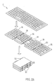
- FIG. 3 is an exploded diagram of a keyboard according to a preferred embodiment of the invention.
- FIG. 4A is a schematic diagram of the keyboard in a packing aspect according to the preferred embodiment of the invention.
- FIG. 4B is a schematic cross sectional diagram of the keyboard along the line A-A' of FIG. 4A ;
- FIG. 4C is a schematic cross sectional diagram of the keyboard along the line B-B' of FIG. 4A ;
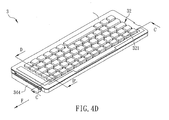
- FIG. 4D is a schematic diagram of the keyboard in an using aspect according to the preferred embodiment of the invention.
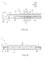
- FIG. 4E is a schematic cross sectional diagram of the keyboard along the line C-C' of FIG. 4E ;
- FIG. 4F is a schematic cross sectional diagram of the keyboard along the line D-D' of FIG. 4D ;
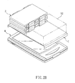
- FIG. 5 is a schematic diagram of a keyboard according to another preferred embodiment of the invention.
- a keyboard 3 includes a first housing 31, a keystroke module 32, a second housing 33, and an actuating assembly 34.
- the keyboard 3 may be an external keyboard or a built-in keyboard of an electronic device (e.g. a personal computer, a laptop, an ultra-mobile PC, or a PDA).
- An external keyboard is used herein as an example of the keyboard 3.
- the first housing 31 includes a plurality of first magnetic elements 311, and at least adjacent two of the first magnetic elements 311 have different polarities.
- the first housing 31 is a lower housing of the keyboard 3.
- the first magnetic element 311 may be a magnet or an electromagnet.
- the first magnetic element 311 is a magnet for example.
- the keystroke module 32 includes at least one key portion 321 and is disposed on the first housing 31.
- the second housing 33 that combines with the first housing 31 is an upper housing of the keyboard 3 and has an opening 331.
- the keystroke module 32 is disposed corresponding to the opening 331.
- the actuating assembly 34 is disposed on the second housing 33 and faces towards the first housing 31.
- the actuating assembly 34 has a base 341 and a plurality of second magnetic elements 342.
- the second magnetic elements 342 are disposed on the base 341 and, as the above-mentioned first magnetic elements 311, the second magnetic elements 342 are magnet. At least adjacent two of the second magnetic elements 342 have different polarities.
- the base 341 of the actuating assembly 34 has at least one extended part 341 a along a length direction of the keystroke module 32. In the embodiment, the actuating assembly 34 with two extended parts 341 a is used as an example.
- the second magnetic elements 342 are disposed on the extended parts 341 a, and the first magnetic elements 311 are disposed corresponding to the second magnetic elements 342.
- the first housing 31 further includes at least one first protruded part 312 and a concave part 313.
- the first protruded part 312 is a protruded block and the concave part 313 is a trench.
- the actuating assembly 34 in the embodiment has at least one second protruded part 343 such as an extended clasp.
- the second protruded part is disposed on the extended part 341 a and is corresponding to the first protruded part 312.
- the keyboard 3 further includes a protective cover 35, which has at least one hole 351, and the key portion 321 is disposed corresponding to the hole 351.
- the actuating assembly 34 further includes a handle 344, which is partially exposed between the first housing 31 and the second housing 33.
- FIGS. 4A to 4C are the schematic diagram and the cross sectional diagrams of the keystroke module 32 of the keyboard 3 at a packing position, respectively. Since the two adjacent first magnetic elements 311a and 311b on the first housing 31 have different polarities (e.g. the first magnetic element 311 a is the N pole and the first magnetic element 311b is the S pole in FIG. 4B ), the two adjacent second magnetic elements 342a and 342b on the actuating assembly 34 also have different polarities (e.g. the second magnetic element 342a is the S pole and the second magnetic element 342b is the N pole in FIG. 4B ).
- the two adjacent first magnetic elements 311a and 311b on the first housing 31 have different polarities (e.g. the first magnetic element 311 a is the N pole and the first magnetic element 311b is the S pole in FIG. 4B )
- the two adjacent second magnetic elements 342a and 342b on the actuating assembly 34 also have different polarities (e.g. the second
- the keyboard 3 is in the packing aspect, since the first magnetic element 311 a and the second magnetic element 342b have the same polarity, a repulsive force is generated. If such repulsive force is strong enough, the first magnetic element 311 a and the second magnetic element 342b will be separated with a distance D. Meanwhile, the keystroke module 32 is not protruded from the opening of the second housing 33 so that the key portion 321 is lower than an upper surface of the protective cover 35 and at a packing position P1 (shown in FIG. 4C ).
- FIGS. 4D to 4F are the schematic diagram and the cross sectional diagrams of the keyboard 3 at a using aspect, respectively.
- the handle 344 of the actuating assembly 34 moves along an actuating direction F
- the handle 344 brings the base 341 and the second magnetic elements 342a and 342b to move along the same direction.
- the keystroke module 32 is fixed on the first housing 31, after the second housing 33 is moved, the key portion 321 of the keystroke module 32 passes through the opening 331. Accordingly, a top of the key portion 321 is over an upper surface of the protective cover 35 and at a using position P2 (shown in FIG. 4F ) so as to make it easier for the users to enter the instruction.
- the sinking direction Y that the second housing 33 moves along is perpendicular to the actuating direction F.
- the first housing 31 may have a concave part 313.
- the second protruded part 343 and the concave part 313 may be cogged with each other (shown in FIG. 4E ) so as to increase the reliability of the keyboard 3.
- another keyboard 3a includes a first housing 31a, a keystroke module 32, a second housing 33a, and an actuating assembly 34. Since the keystroke module 32 and the actuating assembly 34 of the keyboard 3a are described in the keyboard 3 of the previous embodiment, a detailed description will be omitted.
- the difference between the first housing 31a and the second housing 33a of the embodiment and these of the previous embodiment is that the first protruded part 312 and the concave part 313 of the first housing 31 a may be integrally formed with the first housing 31 a directly.
- the protective cover 35 of the above-mentioned embodiment may also be integrally formed with the second housing 33 to form the second housing 33a of this embodiment so as to simplify the structure.
- the magnetic elements are respectively disposed on the first housing and the actuating assembly, and the magnetic elements are separated with a distance.
- the keystroke module may be exposed from or packed in the keyboard by the magnetism of the magnetic elements.
- the keystroke module of the keyboard according to the invention may be packed in the keyboard when it is not in use so as to make the keyboard handier in the using aspect and in the packing aspect.
Landscapes
- Engineering & Computer Science (AREA)
- General Engineering & Computer Science (AREA)
- Theoretical Computer Science (AREA)
- Human Computer Interaction (AREA)
- Physics & Mathematics (AREA)
- General Physics & Mathematics (AREA)
- Computer Hardware Design (AREA)
- Input From Keyboards Or The Like (AREA)
- Push-Button Switches (AREA)
Applications Claiming Priority (1)
| Application Number | Priority Date | Filing Date | Title |
|---|---|---|---|
| CN2007101961453A CN101452783B (zh) | 2007-11-28 | 2007-11-28 | 键盘 |
Publications (2)
| Publication Number | Publication Date |
|---|---|
| EP2065784A2 true EP2065784A2 (de) | 2009-06-03 |
| EP2065784A3 EP2065784A3 (de) | 2010-05-05 |
Family
ID=40114407
Family Applications (1)
| Application Number | Title | Priority Date | Filing Date |
|---|---|---|---|
| EP08167293A Withdrawn EP2065784A3 (de) | 2007-11-28 | 2008-10-22 | Tastatur |
Country Status (2)
| Country | Link |
|---|---|
| EP (1) | EP2065784A3 (de) |
| CN (1) | CN101452783B (de) |
Families Citing this family (3)
| Publication number | Priority date | Publication date | Assignee | Title |
|---|---|---|---|---|
| CN102034631A (zh) * | 2009-09-30 | 2011-04-27 | 英业达股份有限公司 | 键盘模组 |
| JP6264471B2 (ja) * | 2015-04-06 | 2018-01-24 | 京セラドキュメントソリューションズ株式会社 | 画像形成装置 |
| CN110045837B (zh) * | 2018-01-17 | 2022-08-09 | 东莞宝德电子有限公司 | 可分离式机械键盘 |
Family Cites Families (6)
| Publication number | Priority date | Publication date | Assignee | Title |
|---|---|---|---|---|
| JPH07146741A (ja) * | 1993-11-19 | 1995-06-06 | Pfu Ltd | 薄型キーボード |
| FI112422B (fi) * | 2000-04-28 | 2003-11-28 | Nokia Corp | Teleskooppirakenne puhelinlaitetta varten |
| CN2446577Y (zh) * | 2000-08-24 | 2001-09-05 | 达方电子股份有限公司 | 可折叠式键盘 |
| TW534390U (en) * | 2001-12-28 | 2003-05-21 | Darfon Electronics Corp | Retractable keyboard |
| US20040066373A1 (en) * | 2002-10-04 | 2004-04-08 | Michael Wu | Foldable computer keyboard |
| CN2665804Y (zh) * | 2003-12-30 | 2004-12-22 | 诠泰电子科技股份有限公司 | 红外线传输的折合式键盘 |
-
2007
- 2007-11-28 CN CN2007101961453A patent/CN101452783B/zh active Active
-
2008
- 2008-10-22 EP EP08167293A patent/EP2065784A3/de not_active Withdrawn
Also Published As
| Publication number | Publication date |
|---|---|
| CN101452783A (zh) | 2009-06-10 |
| CN101452783B (zh) | 2011-05-11 |
| EP2065784A3 (de) | 2010-05-05 |
Similar Documents
| Publication | Publication Date | Title |
|---|---|---|
| US8104979B2 (en) | Keyboard with keystroke module movably disposed to an opening | |
| KR101304035B1 (ko) | 휴대용 통신 장치의 보호 커버 | |
| US8417303B2 (en) | Mobile device case | |
| KR20210016236A (ko) | 펜 수납이 가능한 커버 및 이를 포함하는 전자 장치 | |
| CN101401394B (zh) | 具有第一外壳上的显示器和第二外壳上的窗口的便携式设备 | |
| US6847519B2 (en) | Phone with automatic linked qwerty keyboard | |
| US9678535B2 (en) | Moveable keyboard lattice for a portable electronic device | |
| US9223339B2 (en) | Portable terminal with detachable protection cover | |
| CN101452783B (zh) | 键盘 | |
| JP4460500B2 (ja) | 携帯端末装置 | |
| TWI539985B (zh) | 遊戲控制器套件 | |
| CN214756492U (zh) | 折叠屏护套 | |
| CN1371567A (zh) | 便携式电话 | |
| KR101307635B1 (ko) | 휴대용 통신 장치의 보호 커버 | |
| US20050259071A1 (en) | Secure enclosure for portable electronic display device operated by push buttons | |
| CN217159802U (zh) | 折叠保护套 | |
| KR100606058B1 (ko) | 슬라이딩 액정부를 구비한 무선 단말기 | |
| KR102603685B1 (ko) | 이동식 단말기 커버케이스 | |
| TWM453892U (zh) | 輔助輸入裝置 | |
| JP5160118B2 (ja) | 携帯端末装置及び表示方法 | |
| JP5428718B2 (ja) | 携帯端末装置 | |
| KR101094963B1 (ko) | 이중-개방 플랩을 갖는 개인용 오락 디바이스(ped) | |
| JP4796973B2 (ja) | 折り畳み式携帯端末機 | |
| KR200469824Y1 (ko) | 휴대용 통신 장치의 보호 커버 | |
| KR101487237B1 (ko) | 휴대단말기 케이스 |
Legal Events
| Date | Code | Title | Description |
|---|---|---|---|
| PUAI | Public reference made under article 153(3) epc to a published international application that has entered the european phase |
Free format text: ORIGINAL CODE: 0009012 |
|
| AK | Designated contracting states |
Kind code of ref document: A2 Designated state(s): AT BE BG CH CY CZ DE DK EE ES FI FR GB GR HR HU IE IS IT LI LT LU LV MC MT NL NO PL PT RO SE SI SK TR |
|
| AX | Request for extension of the european patent |
Extension state: AL BA MK RS |
|
| PUAL | Search report despatched |
Free format text: ORIGINAL CODE: 0009013 |
|
| AK | Designated contracting states |
Kind code of ref document: A3 Designated state(s): AT BE BG CH CY CZ DE DK EE ES FI FR GB GR HR HU IE IS IT LI LT LU LV MC MT NL NO PL PT RO SE SI SK TR |
|
| AX | Request for extension of the european patent |
Extension state: AL BA MK RS |
|
| AKY | No designation fees paid | ||
| STAA | Information on the status of an ep patent application or granted ep patent |
Free format text: STATUS: THE APPLICATION IS DEEMED TO BE WITHDRAWN |
|
| 18D | Application deemed to be withdrawn |
Effective date: 20101106 |
|
| REG | Reference to a national code |
Ref country code: DE Ref legal event code: R108 Effective date: 20110405 Ref country code: DE Ref legal event code: 8566 |