EP1150148B1 - Verbindungsmodul - Google Patents
Verbindungsmodul Download PDFInfo
- Publication number
- EP1150148B1 EP1150148B1 EP01109925A EP01109925A EP1150148B1 EP 1150148 B1 EP1150148 B1 EP 1150148B1 EP 01109925 A EP01109925 A EP 01109925A EP 01109925 A EP01109925 A EP 01109925A EP 1150148 B1 EP1150148 B1 EP 1150148B1
- Authority
- EP
- European Patent Office
- Prior art keywords
- module
- ferrule
- housing
- accordance
- halves
- Prior art date
- Legal status (The legal status is an assumption and is not a legal conclusion. Google has not performed a legal analysis and makes no representation as to the accuracy of the status listed.)
- Expired - Lifetime
Links
Images






Classifications
-
- G—PHYSICS
- G02—OPTICS
- G02B—OPTICAL ELEMENTS, SYSTEMS OR APPARATUS
- G02B6/00—Light guides; Structural details of arrangements comprising light guides and other optical elements, e.g. couplings
- G02B6/24—Coupling light guides
- G02B6/36—Mechanical coupling means
- G02B6/38—Mechanical coupling means having fibre to fibre mating means
- G02B6/3807—Dismountable connectors, i.e. comprising plugs
- G02B6/3869—Mounting ferrules to connector body, i.e. plugs
-
- G—PHYSICS
- G02—OPTICS
- G02B—OPTICAL ELEMENTS, SYSTEMS OR APPARATUS
- G02B6/00—Light guides; Structural details of arrangements comprising light guides and other optical elements, e.g. couplings
- G02B6/24—Coupling light guides
- G02B6/36—Mechanical coupling means
- G02B6/38—Mechanical coupling means having fibre to fibre mating means
- G02B6/3807—Dismountable connectors, i.e. comprising plugs
- G02B6/3873—Connectors using guide surfaces for aligning ferrule ends, e.g. tubes, sleeves, V-grooves, rods, pins, balls
- G02B6/3874—Connectors using guide surfaces for aligning ferrule ends, e.g. tubes, sleeves, V-grooves, rods, pins, balls using tubes, sleeves to align ferrules
- G02B6/3878—Connectors using guide surfaces for aligning ferrule ends, e.g. tubes, sleeves, V-grooves, rods, pins, balls using tubes, sleeves to align ferrules comprising a plurality of ferrules, branching and break-out means
-
- G—PHYSICS
- G02—OPTICS
- G02B—OPTICAL ELEMENTS, SYSTEMS OR APPARATUS
- G02B6/00—Light guides; Structural details of arrangements comprising light guides and other optical elements, e.g. couplings
- G02B6/24—Coupling light guides
- G02B6/36—Mechanical coupling means
- G02B6/38—Mechanical coupling means having fibre to fibre mating means
- G02B6/3807—Dismountable connectors, i.e. comprising plugs
- G02B6/389—Dismountable connectors, i.e. comprising plugs characterised by the method of fastening connecting plugs and sockets, e.g. screw- or nut-lock, snap-in, bayonet type
- G02B6/3893—Push-pull type, e.g. snap-in, push-on
Definitions
- connection module with an outer housing, at least an optical ferrule and a module housing for receiving the ferrule with the features of the preamble of claim 1, as e.g. from US 4,611,887 is known.
- Optical ferrules serve as connecting elements or terminals of Optical fibers, as for example in motor vehicles for transmission be used by signals.
- connection modules used to hold one or more Ferrules serve.
- connection modules used to hold one or more Ferrules serve.
- connection module to create the type mentioned, if possible easy manufacturability the inclusion of ferrules with minimal positioning tolerances allowed.
- the inventively adapted to the outer shape of the ferrule recesses allow either insert the ferrule in a module half and by assembling the two module halves in the receiving space to arrange or the ferrule with assembled module housing in to insert the receiving space formed by the wells.
- the receiving space formed by the depressions has at least in essentially the shape of the ferrule. Therefore, according to the invention, positioning tolerances, the by playing the arranged in the module ferrule be caused and affect a signal transmission at Simultaneous ease of manufacture and handling of the module housing forming module halves are minimized.
- a locking device for the Ferrule on by inserting the assembled module housing is securable in the outer housing in a locking position.
- the outer housing, in which the assembled module housing can be inserted serves here the outer housing, in which the assembled module housing can be inserted.
- the Wells at least partially as an impression of the ferrule educated.
- the recesses are thus a negative of a part of the ferrule. hereby is a tolerance-free positive connection between the ferrule and the assembled to form the module housing module halves guaranteed.
- the depressions can each as a exact impression of a half of the ferrule are formed. hereby Can the ferrule alone by inserting into the recess of a module half and final assembly of the two module halves in one operation be adjusted and locked in the receiving space. Additional measures for securing and fixing the ferrule in the module housing are not required.
- the Module halves identical. This results in the production the module halves by itself a high dimensional accuracy, as essentially identical tools, especially injection molds, for the two halves can be used. Furthermore, the module halves here with respect to the receiving space a tool independent Shape up and use the same tool, in particular be manufactured with the same injection mold. this leads to extremely high dimensional accuracy and significantly improved Tolerance minimization.
- module halves in such a way that they exist only by means of mutual connection, in particular Locking, and / or by means of fixation, in particular Clamp ferrule differ from each other.
- the module halves can in a variant of the invention as a separate Be provided components.
- the module halves are latched together in particular without play.
- connecting means such as locking means an advantageous self-adjustment of the module halves during assembly allowing positioning tolerances of the ferrule in the Connection module can be minimized.
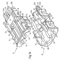
- connection module according to FIGS. 1-3 comprises two completely identical ones Module halves 14, 16, the separate, injection-molded plastic manufactured components are.
- Fig. 1a shows the connection module during assembly, while in Fig. 2, the composite connection module is shown.
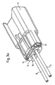
- Fig. 3a shows the connection module with therein arranged and coupled with optical fibers 13 ferrules, partially is inserted in an outer housing 15.
- the as connecting elements or Terminals for the light guide 13 serving cylindrical ferrules are so formed, as in Fig. 4 in conjunction with another, at another Site explained embodiment shown and described.
- each module half 14, 16 comprises two identically designed Recesses 24, 26, the assembled module with two receiving spaces form for the ferrules.
- locking arms 27th limited recesses 24, 26 corresponds substantially to the outer Shape or contour of the ferrules to be picked up.
- the depressions 24, 26 are thus partially an impression or a negative of the ferrules.
- Composite module housing thus has a positive fit Connection between the module housing and arranged therein Ferrules, whereby the ferrules positioned without play in the module housing are.
- the locking means 27 are each in the form of an elastic deflectable latching arm 27 with a U-shaped or trough-shaped half shell trained engaging portion 29 is provided.
- the latching arms 27 are by inserting the ferrules in the composite Module housing 14, 16 formed by the recesses 24, 26 Receiving spaces perpendicular to the insertion elastically deflectable. Due to the elastic deformability of the locking arms 27 jump the latching arms 27 each in a circumferential groove 11 (see Fig .. 4) of the respective Ferrule back when the ferrule is completely in the receiving space is plugged in.
- the ferrules can thus with assembled module housing 14, 16 be plugged into the receiving spaces, while in the fully inserted Condition by the engaging portions 29 of the locking arms 27 shallziehêt be held in the module housing 14, 16.
- FIG. 1b The perspective top view of a module half 16 according to FIG. 1b shows in particular the latching arms 27 and at the free end of the latching arms 27 formed engaging portions 29th
- each module half 14, 16 differently formed on opposite module sides Locking means 32, 33 and 34 (see Fig. 1a).
- These locking means 32, 33, 34 are with a slightly positive locking angle provided, whereby a backlash-free locking of the two module halves 14, 16 and thus ensures a tolerance-minimized positioning of the ferrules is.
- the locking ensures a self-adjustment of the module during assembly the module halves 14, 16, since the locking means 32, 33, 34 such coordinated with each other, that the module halves 14, 16 only in one single relative position can be assembled.
- each module half 14, 16 with connecting means in the form of a cantilevered forward locking arm 54 and 56 provided.
- Each latching arm 54, 56 has two latching sections 54a, 54b and 56a, 56b provided in the assembled Connecting module of FIG. 2 together with also above lateral wall sections 55a, 55b and 57a, 57b latching receptacles for form the Gegenferrulen.
- the latching arms 54, 56 are designed such that the light entry or Light exit surfaces of ferrules in for a reliable signal transmission optimally oriented relative to each other opposite each other.
- the module halves 14, 16 on a module side with a Locking arm 64 provided.
- the latching arm 64 is at one end with a connected between the two projections 34 arranged tab 65 and angled at a slight distance from the tab 65 by about 90 °, that it is essentially parallel to the module side to the rear extends, wherein the free end of the latching arm 64 is not on the back the respective module half 14 and 16 protrudes.
- the latching arms 64 serve for latching the composite connection module in an outer housing 15 (see Fig. 3a, 3b, 3c).
- the outer housing 15 has inside latching means which are connected to the latching arms 64 and with formed on the outside of the locking arms 64 projections such cooperate, that a two-stage locking of the compound Connection module in the housing 15 is possible.
- the module housing composed of the two module halves 14, 16 or connecting module without ferrules disposed therein in one pre-locked state stored in the housing 15 and transported.
- This pre-latched state is the module housing via its latching arms 64 fall arrested locked in the outer housing 15.
- the ferrules in the module housing 14, 16 are in this first Verrastungsshake between module housing 14, 16 and outer housing 15 the ferrules with the coupled optical fibers 13 from the rear in the receiving spaces of the module formed by the recesses 24, 26 plugged in.
- the interior of the outer casing is 15 is formed so that in this Vorverrastungs phenomenon, i. in the first latching stage (see Fig. 3b), the latching arms 27 of the module halves 14, 16 by inserting the ferrules perpendicular to the insertion direction can be pushed away or deflected.
- the ferrules are thus completely in this VorverrastungsSullivan in the module housing 14, 16 insertable and are in the fully inserted state of the engagement portions 29 of the jump back to their original position Locking arms 27 locking behind.
- the module housing 14, 16 After inserting the ferrules, the module housing 14, 16 is complete inserted into the outer housing 15 until it in the second and final Verrastungstress in the outer housing 15 engages (see Fig. 3c).
- the outer housing 15 is provided with securing portions 17 which at completely plugged into the outer housing 15 module housing 14, 16th are arranged relative to the latching arms 27 such that the latching arms 27th can not be deflected. The locking of the ferrules in the module housing 14, 16 by the latching arms 27 is thus through the outer housing secured.
- Fig. 3 shows the plugged into the outer housing 15 connection module 14, 16 in the state of Vorverrastung, in which the module 14, 16 still is not fully inserted into the housing 15 and the ferrules with the coupled optical fibers 13 completely into the assembled module housing 14, 16 are inserted.
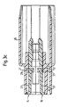
- 3b shows a sectional side view of the Vorverrastrus, in which the engagement portions 29 of the latching arms 27 in the insertion direction located in front of the securing portions 17 of the outer housing 15. Between the latching arms 27 and the wall of the outer housing 15th There is a gap in which the latching arms 27 dodge can, if in the module housing 14, 16, the respective ferrule (not shown) is inserted.
- FIG. 3c shows the module housing 14, 16 in fully inserted into the outer housing 15 state, in which the securing portions 17 of the outer housing 15, the latching arms Secure 27 in its locked position.
- final Verrastungstress of the module housing 14, 16 in the outer housing 15 is a Release or unlocking movement of the latching arms 27 perpendicular to Insertion direction not possible.
- the back of the module housing 14, 16 Closes in this state substantially flush with the rear End face of the outer housing 15 from.
- connection module differs from that of Figs. 1-3 substantially by the configuration of the recesses 24, 26 and by the means for connecting the module halves 14, 16.
- the module housing is as a one-piece Component provided, wherein the two module halves 14, 16 by a two axially spaced hinge sections comprising film hinge 28th are hinged together.
- connection module could also by a two-component spraying are made, in which one the two Module halves 14, 16 hingedly interconnecting hinge, for example consists of an elastomer and the two module halves 14, 16 are made of a material that is not or only slightly Dimensions elastically deformable. For example, this material comes reinforced plastic in question.
- An advantage of this variant is that the strength of the ferrules 12 receiving module halves 14, 16th can be increased because the connection module or module housing only is elastically deformable in the hinge area.
- connection of the hinge area to the module halves 14, 16 can be configured such that by the hinge a bias voltage in the closing direction of the module halves 14, 16 can be achieved, i. Over the hinge area is on the module halves 14, 16 a force exercised, which seeks to close the module housing.
- connection module facilitates its manageability, since the two module halves 14, 16 always exist together.
- Fig. 4 also shows the coupled to one end of a light guide 13, respectively Ferrules into the recesses 26 of a module half 16 of the opened connection module are inserted.
- the recesses 24, 26 as exact impression or exact negative of a ferrule half formed, whereby in assembled module housing an exact positive Connection between the ferrules 12 and the module halves 14, 16 is effected.
- the recesses 24, 26 engage the Module halves 14, 16 in the circumferential groove 11 of the ferrule 12, whereby the ferrules 12 in the recesses 24, 26 formed by the receiving cavities are locked. Additional means for locking the ferrules 12 or to secure the lock are in this embodiment not mandatory.
- this embodiment corresponds to that of Fig. 1-3.
- the ferrules 12 are opened Module housing in the wells 24 and 26 one of the two Module halves 14 and 16 inserted. Subsequently, the module housing by folding and locking the two module halves 14, 16 locked. Due to the exact adaptation of the recesses 24, 26 to the outer shape of the ferrule 12, these are in assembled module housing arranged without play in the recording rooms.
- Fig. 5 shows the connection module in the closed Status.
- the two sections of the film hinge 28 while recognizing on the opposite Module side the two module halves 14, 16 are locked together, whereby the module is held securely in the closed state.
- this can consist of the two module halves 14, 16 assembled module housing or connection module already as full connector can be used, since the ferrules 12 alone due the configuration of the module halves 14, 16 and the wells 24, 26 are arranged finallyziehêt in the module housing.
- Fig. 6 shows, however, the housing module 14, 16 inserted into an outer housing 15 are identical to that with reference to FIG. 3 in connection explained with the first described embodiment of the invention Outer housing can be executed.
- the outer housing 15 is not required.
- each Module half 14 For locking with the outer housing 15 are in the front area of each Module half 14, 16 locking projections 68 are provided.
- the latching projections 68 be in the fully inserted state of internal locking means of the Housing 15 e.g. in the form of locking hooks or locking arms locking engaged behind.
Landscapes
- Physics & Mathematics (AREA)
- General Physics & Mathematics (AREA)
- Optics & Photonics (AREA)
- Mechanical Coupling Of Light Guides (AREA)
- Optical Couplings Of Light Guides (AREA)
Description
- Fig. 1 - 3
- ein Verbindungsmodul gemäß einer Ausführungsform der Erfindung, und
- Fig. 4 - 6
- ein Verbindungsmodul, das nicht unter Anspruch 1 fällt, jedoch für das Verständnis der anhand von Fig. 1-3 beschriebenen Erfindung hilfreich ist.
- 11
- Umfangsnut
- 12
- Ferrule
- 13
- Lichtleiter
- 14
- Modulhälfte
- 15
- Außengehäuse
- 16
- Modulhälfte
- 17
- Sicherungsabschnitt
- 24
- Vertiefung
- 26
- Vertiefung
- 27
- Verriegelungseinrichtung, Rastarm
- 28
- Filmscharnier
- 29
- Eingriffsabschnitt
- 32
- Lasche
- 33
- Öffnung
- 34
- Vorsprung
- 42
- Lasche
- 43
- Öffnung
- 44
- Vorsprung
- 54
- Rastarm
- 54a, 54b
- Rastabschnitt
- 55a, 55b
- Wandabschnitt
- 56
- Rastarm
- 56a, 56b
- Rastabschnitt
- 57a, 57b
- Randabschnitt
- 64
- Rastarm
- 65
- Lasche
- 68
- Rastvorsprung
Claims (15)
- Verbindungsmodul mit einem Außengehäuse (15), wenigstens einer optischen Ferrule (12) und einem Modulgehäuse (14, 16) zur Aufnahme der Ferrule (12), das in einer Ebene entlang der axialen Richtung geteilt ist und aus zwei Modulhälften (14, 16) besteht, die bei zusammengesetztem Modulgehäuse einen Aufnahmeraum für die Ferrule (12) begrenzen, der von in den Modulhälften (14, 16) ausgebildeten und an die äußere Form der Ferrule (12) angepaßten Vertiefungen (24, 26) gebildet ist,
dadurch gekennzeichnet, daß die Vertiefungen (24, 26) derart ausgeführt sind, daß die Ferrule (12) bei zusammengesetztem Modulgehäuse (14, 16) in den von den Vertiefungen (24, 26) gebildeten Aufnahmeraum einsteckbar ist, und
daß zumindest eine Modulhälfte (14, 16) eine Verriegelungseinrichtung (27) für die Ferrule (12) aufweist, die durch Einstecken des zusammengesetzten Modulgehäuses in das Außengehäuse (15) in einer Verriegelungsstellung sicherbar ist. - Verbindungsmodul nach Anspruch 1,
dadurch gekennzeichnet, daß die Verriegelungseinrichtung wenigstens einen Rastarm (27) aufweist, der bei zusammengesetztem Modulgehäuse (14, 16) durch Einstecken der Ferrule (12) in den Aufnahmeraum aus einer Verriegelungsstellung elastisch auslenkbar ist. - Verbindungsmodul nach Anspruch 1 oder 2,
dadurch gekennzeichnet, daß die Vertiefungen (24, 26) jeweils zumindest bereichsweise als ein Abdruck der Ferrule (12) ausgebildet sind. - Verbindungsmodul nach einem der vorhergehenden Ansprüche,
dadurch gekennzeichnet, daß die Modulhälften (14, 16) identisch ausgeführt sind. - Verbindungsmodul nach einem der Ansprüche 1 bis 3,
dadurch gekennzeichnet, daß die Modulhälften (14, 16) sich lediglich durch Mittel zur gegenseitigen Verbindung, insbesondere Verrastung, und/oder durch Mittel zur Fixierung der Ferrule (12) voneinander unterscheiden. - Verbindungsmodul nach einem der vorhergehenden Ansprüche,
dadurch gekennzeichnet, daß die Vertiefungen (24, 26) jeweils als ein exakter Abdruck einer Hälfte der Ferrule (12) ausgebildet sind. - Verbindungsmodul nach einem der vorhergehenden Ansprüche,
dadurch gekennzeichnet, daß die Modulhälften (14, 16) als separate Bauteile vorgesehen sind. - Verbindungsmodul nach einem der vorhergehenden Ansprüche,
dadurch gekennzeichnet, daß die Modulhälften (14, 16) jeweils Verbindungsmittel (64), insbesondere Rastmittel, zur Koppelung mit dem zur Aufnahme des Modulgehäuses dienenden Außengehäuse (15) aufweisen. - Verbindungsmodul nach Anspruch 8,
dadurch gekennzeichnet, daß als Verbindungsmittel jeweils ein sich zumindest bereichsweise im wesentlichen parallel zu einer Modulseite erstreckender Rastarm (64) vorgesehen ist. - Verbindungsmodul nach Anspruch 8 oder 9,
dadurch gekennzeichnet, daß die Verbindungsmittel (64) für eine zweistufige Verrastung des Modulgehäuses (14, 16) im Außengehäuse (15) ausgebildet sind. - Verbindungsmodul nach einem der vorhergehenden Ansprüche,
dadurch gekennzeichnet, daß die Modulhälften (14, 16) miteinander insbesondere spielfrei verrastbar sind. - Verbindungsmodul nach einem der vorhergehenden Ansprüche,
dadurch gekennzeichnet, daß Rastmittel jeder Modulhälfte (14, 16) auf einer Modulseite wenigstens eine mit einer Öffnung (33) versehene Lasche (32) und auf der gegenüberliegenden Modulseite zumindest einen Vorsprung (34) umfassen. - Verbindungsmodul nach einem der Ansprüche 1 bis 11,
dadurch gekennzeichnet, daß als Rastmittel der einen Modulhälfte (14) wenigstens eine mit einer Öffnung (43) versehene Lasche (42) und als Rastmittel der anderen Modulhälfte (16) zumindest ein Vorsprung (44) vorgesehen ist. - Verbindungsmodul nach einem der vorhergehenden Ansprüche,
dadurch gekennzeichnet, daß die Modulhälften (14, 16) jeweils Verbindungsmittel (54, 56), insbesondere Rastmittel, zur Koppelung mit einer Gegenferrule aufweisen. - Verbindungsmodul nach Anspruch 14,
dadurch gekennzeichnet, daß die Rastmittel in Form wenigstens eines auskragenden Rastarmes (54) vorgesehen sind, der bei zusammengesetztem Modulgehäuse mit zumindest einem Rastarm (56) der jeweils anderen Modulhälfte (16) eine Rastaufnahme für die Gegenferrule bildet.
Applications Claiming Priority (2)
| Application Number | Priority Date | Filing Date | Title |
|---|---|---|---|
| DE10020675A DE10020675A1 (de) | 2000-04-27 | 2000-04-27 | Verbindungsmodul |
| DE10020675 | 2000-04-27 |
Publications (3)
| Publication Number | Publication Date |
|---|---|
| EP1150148A2 EP1150148A2 (de) | 2001-10-31 |
| EP1150148A3 EP1150148A3 (de) | 2002-04-10 |
| EP1150148B1 true EP1150148B1 (de) | 2005-02-23 |
Family
ID=7640126
Family Applications (1)
| Application Number | Title | Priority Date | Filing Date |
|---|---|---|---|
| EP01109925A Expired - Lifetime EP1150148B1 (de) | 2000-04-27 | 2001-04-24 | Verbindungsmodul |
Country Status (2)
| Country | Link |
|---|---|
| EP (1) | EP1150148B1 (de) |
| DE (2) | DE10020675A1 (de) |
Family Cites Families (11)
| Publication number | Priority date | Publication date | Assignee | Title |
|---|---|---|---|---|
| US4547039A (en) * | 1982-04-16 | 1985-10-15 | Amp Incorporated | Housing mountable on printed circuit board to interconnect fiber optic connectors |
| JPS58211724A (ja) * | 1982-06-04 | 1983-12-09 | Yazaki Corp | 光フアイバ−線用コネクタ |
| US4611887A (en) * | 1983-02-24 | 1986-09-16 | Amp Incorporated | Fiber optic connector assembly and wall outlet thereof |
| JPH06100698B2 (ja) * | 1984-06-08 | 1994-12-12 | アンプ・インコ−ポレ−テッド | 光ファイバコネクタ組立体 |
| US5166995A (en) * | 1984-06-08 | 1992-11-24 | Amp Incorporated | Polarized connector |
| US4744629A (en) * | 1985-08-16 | 1988-05-17 | Augat Inc. | Multifiber optical cable connector |
| FR2593294B1 (fr) * | 1986-01-23 | 1990-01-05 | Alsthom Cgee | Connecteur pour fibres optiques |
| US5138678A (en) * | 1991-09-20 | 1992-08-11 | Briggs Robert C | Connector with a variable direction strain relief |
| US5315679A (en) * | 1992-04-27 | 1994-05-24 | International Business Machines Corporation | Optical fibers duplex connector assembly |
| JP3209044B2 (ja) * | 1995-06-13 | 2001-09-17 | 住友電装株式会社 | 光コネクタ及び光コネクタへの光ファイバの固定方法 |
| FR2774181B1 (fr) * | 1998-01-28 | 2001-10-26 | Proptic | Dispositif de connexion/deconnexion de deux fibres optiques individuelles et epanouisseur-connecteur pour fibres optiques |
-
2000
- 2000-04-27 DE DE10020675A patent/DE10020675A1/de not_active Withdrawn
-
2001
- 2001-04-24 DE DE50105400T patent/DE50105400D1/de not_active Expired - Fee Related
- 2001-04-24 EP EP01109925A patent/EP1150148B1/de not_active Expired - Lifetime
Also Published As
| Publication number | Publication date |
|---|---|
| EP1150148A2 (de) | 2001-10-31 |
| EP1150148A3 (de) | 2002-04-10 |
| DE50105400D1 (de) | 2005-03-31 |
| DE10020675A1 (de) | 2001-10-31 |
Similar Documents
| Publication | Publication Date | Title |
|---|---|---|
| DE69408344T2 (de) | Optischer Stecker | |
| EP0570652B1 (de) | Steckverbindung für Lichtwellenleiter | |
| DE3780481T2 (de) | Koppler fuer optische fasern. | |
| EP0805366A1 (de) | Steckverbindung | |
| DE19858091A1 (de) | Elektrischer Verbinder mit verblockendem integrierten Scharnier | |
| WO2002042818A1 (de) | Stecker für lichtwellenleiter mit einem steckergehäuse | |
| DE69705658T2 (de) | Modularer Aufbau, bestehend aus mehreren Einheiten, mit den entsprechenden Steckverbindern | |
| EP0317755A1 (de) | Mehrpolige steckbare Kupplungshälfte für elektrische Leitungen | |
| DE69902863T2 (de) | Wasserdichter Verbinder | |
| DE112005000467T5 (de) | Steckverbinder | |
| DE19641408A1 (de) | Wasserdichter Steckverbinder | |
| DE10357194A1 (de) | Verbinder und Verbinderanordnung | |
| DE102019212180A1 (de) | Hebelverbinder | |
| DE19516241A1 (de) | Lichtwellenleiterverbinder | |
| DE69926235T2 (de) | Steckerstift für optischen stecker, methode zu seiner herstellung und optischer stecker mit einem solchen steckerstift | |
| DE19910027A1 (de) | Mit geringer Kraft kuppelbarer Steckverbinder | |
| DE4404112A1 (de) | Wasserdichter Stecker vom Hebelverschlußtyp | |
| EP2043199A1 (de) | Steckverbinder | |
| DE19959987C2 (de) | Leichtgängige Steckverbinder-Baugruppe | |
| EP1126557B1 (de) | Elektrischer Steckverbinder | |
| EP0452555A1 (de) | Steckverbinder, insbesondere Zwittersteckverbinder | |
| DE69500577T2 (de) | Steckverbinder mit sekundärem Verriegelungsgitter für die Anschlusselemente | |
| DE4416004C1 (de) | Gehäuse, insbesondere zur Aufnahme elektrischer oder elektronischer Bauteile | |
| DE2627662A1 (de) | Verbinder fuer lichtleitkabel | |
| EP1150148A2 (de) | Verbindungsmodul |
Legal Events
| Date | Code | Title | Description |
|---|---|---|---|
| PUAI | Public reference made under article 153(3) epc to a published international application that has entered the european phase |
Free format text: ORIGINAL CODE: 0009012 |
|
| AK | Designated contracting states |
Kind code of ref document: A2 Designated state(s): AT BE CH CY DE DK ES FI FR GB GR IE IT LI LU MC NL PT SE TR Kind code of ref document: A2 Designated state(s): DE FR IT |
|
| AX | Request for extension of the european patent |
Free format text: AL;LT;LV;MK;RO;SI |
|
| PUAL | Search report despatched |
Free format text: ORIGINAL CODE: 0009013 |
|
| AK | Designated contracting states |
Kind code of ref document: A3 Designated state(s): AT BE CH CY DE DK ES FI FR GB GR IE IT LI LU MC NL PT SE TR |
|
| AX | Request for extension of the european patent |
Free format text: AL;LT;LV;MK;RO;SI |
|
| 17P | Request for examination filed |
Effective date: 20020529 |
|
| 17Q | First examination report despatched |
Effective date: 20020927 |
|
| AKX | Designation fees paid |
Free format text: DE FR IT |
|
| GRAP | Despatch of communication of intention to grant a patent |
Free format text: ORIGINAL CODE: EPIDOSNIGR1 |
|
| GRAS | Grant fee paid |
Free format text: ORIGINAL CODE: EPIDOSNIGR3 |
|
| GRAA | (expected) grant |
Free format text: ORIGINAL CODE: 0009210 |
|
| AK | Designated contracting states |
Kind code of ref document: B1 Designated state(s): DE FR IT |
|
| REG | Reference to a national code |
Ref country code: IE Ref legal event code: FG4D Free format text: GERMAN |
|
| REF | Corresponds to: |
Ref document number: 50105400 Country of ref document: DE Date of ref document: 20050331 Kind code of ref document: P |
|
| ET | Fr: translation filed | ||
| PLBE | No opposition filed within time limit |
Free format text: ORIGINAL CODE: 0009261 |
|
| STAA | Information on the status of an ep patent application or granted ep patent |
Free format text: STATUS: NO OPPOSITION FILED WITHIN TIME LIMIT |
|
| 26N | No opposition filed |
Effective date: 20051124 |
|
| PGFP | Annual fee paid to national office [announced via postgrant information from national office to epo] |
Ref country code: DE Payment date: 20070419 Year of fee payment: 7 |
|
| PGFP | Annual fee paid to national office [announced via postgrant information from national office to epo] |
Ref country code: IT Payment date: 20070515 Year of fee payment: 7 |
|
| PGFP | Annual fee paid to national office [announced via postgrant information from national office to epo] |
Ref country code: FR Payment date: 20070411 Year of fee payment: 7 |
|
| PG25 | Lapsed in a contracting state [announced via postgrant information from national office to epo] |
Ref country code: DE Free format text: LAPSE BECAUSE OF NON-PAYMENT OF DUE FEES Effective date: 20081101 |
|
| REG | Reference to a national code |
Ref country code: FR Ref legal event code: ST Effective date: 20081231 |
|
| PG25 | Lapsed in a contracting state [announced via postgrant information from national office to epo] |
Ref country code: FR Free format text: LAPSE BECAUSE OF NON-PAYMENT OF DUE FEES Effective date: 20080430 |
|
| PG25 | Lapsed in a contracting state [announced via postgrant information from national office to epo] |
Ref country code: IT Free format text: LAPSE BECAUSE OF NON-PAYMENT OF DUE FEES Effective date: 20080424 |