EP1149700A2 - Dosiersystem für eine Beschichtungseinheit in einer Druckmaschine - Google Patents
Dosiersystem für eine Beschichtungseinheit in einer Druckmaschine Download PDFInfo
- Publication number
- EP1149700A2 EP1149700A2 EP01109264A EP01109264A EP1149700A2 EP 1149700 A2 EP1149700 A2 EP 1149700A2 EP 01109264 A EP01109264 A EP 01109264A EP 01109264 A EP01109264 A EP 01109264A EP 1149700 A2 EP1149700 A2 EP 1149700A2
- Authority
- EP
- European Patent Office
- Prior art keywords
- roller
- dosing system
- plating device
- coating fluid
- plating
- Prior art date
- Legal status (The legal status is an assumption and is not a legal conclusion. Google has not performed a legal analysis and makes no representation as to the accuracy of the status listed.)
- Granted
Links
- 239000011248 coating agent Substances 0.000 title claims abstract description 73
- 238000000576 coating method Methods 0.000 title claims abstract description 73
- 238000007639 printing Methods 0.000 title claims abstract description 9
- 238000007747 plating Methods 0.000 claims abstract description 78
- 239000012530 fluid Substances 0.000 claims abstract description 65
- 230000006835 compression Effects 0.000 claims description 3
- 238000007906 compression Methods 0.000 claims description 3
- 238000003860 storage Methods 0.000 claims description 2
- 238000012876 topography Methods 0.000 description 17
- 239000003973 paint Substances 0.000 description 9
- 238000012549 training Methods 0.000 description 8
- 239000004922 lacquer Substances 0.000 description 6
- 230000008859 change Effects 0.000 description 5
- 239000004033 plastic Substances 0.000 description 5
- 238000013461 design Methods 0.000 description 4
- 238000010008 shearing Methods 0.000 description 4
- 230000009471 action Effects 0.000 description 3
- 230000008901 benefit Effects 0.000 description 3
- 238000007493 shaping process Methods 0.000 description 3
- 238000011161 development Methods 0.000 description 2
- 238000000034 method Methods 0.000 description 2
- 230000008569 process Effects 0.000 description 2
- 238000012216 screening Methods 0.000 description 2
- 238000009827 uniform distribution Methods 0.000 description 2
- 239000002966 varnish Substances 0.000 description 2
- 230000001914 calming effect Effects 0.000 description 1
- 239000003795 chemical substances by application Substances 0.000 description 1
- 238000005253 cladding Methods 0.000 description 1
- 238000003776 cleavage reaction Methods 0.000 description 1
- 238000004891 communication Methods 0.000 description 1
- 230000001419 dependent effect Effects 0.000 description 1
- 230000000694 effects Effects 0.000 description 1
- 238000007667 floating Methods 0.000 description 1
- 239000000463 material Substances 0.000 description 1
- 230000035515 penetration Effects 0.000 description 1
- 238000005096 rolling process Methods 0.000 description 1
- 230000007017 scission Effects 0.000 description 1
- 238000007789 sealing Methods 0.000 description 1
- 238000000926 separation method Methods 0.000 description 1
- 239000000758 substrate Substances 0.000 description 1
- 230000032258 transport Effects 0.000 description 1
Images


Classifications
-
- B—PERFORMING OPERATIONS; TRANSPORTING
- B41—PRINTING; LINING MACHINES; TYPEWRITERS; STAMPS
- B41F—PRINTING MACHINES OR PRESSES
- B41F23/00—Devices for treating the surfaces of sheets, webs, or other articles in connection with printing
- B41F23/08—Print finishing devices, e.g. for glossing prints
Definitions
- the invention relates to a metering system for a coating unit, especially for a coating unit, in a printing press according to the preamble of the main claim.
- a metering system of this type is known from DE 34 27 898 C1 and can be used in particular in a coating unit.
- the dosing system has a forme cylinder with an application roller is in functional connection.
- the applicator roller is a metering roller assigned and in the formed by both rollers
- the nip becomes the coating fluid from above via a feed pipe fed. About turbulence, air pockets or to avoid inconsistent order quantities is in the filled nip a separating element with communication openings used.
- a scoop roller immersed in a paint reservoir is functionally connected to a metering roller.
- the metering roller feeds the varnish to a rubber-coated applicator roller, which acts as a forme cylinder.
- a metering system is known in which the scoop roller immersed in the reservoir can be driven in reverse operation, a doctor blade being employed as an additional metering point for the scoop roller.
- a dosing system is known from DE 43 11 834 A1, through a forme cylinder, a screened application roller and one with this applicator roller in functional connection standing doctor blade system is formed.
- the invention is based on the object of a metering system of the type mentioned at the beginning to create that with little Effort a uniform, stable guidance of a coating fluid, for example paint, on at least one roller surface achieved and the print quality noticeably improved.
- a coating fluid for example paint
- the coating fluid has been split (separation of the coating fluid layer) in a contact zone with a forme cylinder by tearing off the coating fluid, for example lacquer, especially when thread-like tearing off, there is no uniform distribution of the coating fluid over the roller width, but an uneven surface topography the remaining coating fluid, for example the residual lacquer, on the outer surface of the application roller.
- a first advantage of the invention is based on the fact that, in the case of an uneven surface topography (peaks, peaks and valleys) of coating fluid, for example lacquer, which results from a previous tearing off of the coating fluid, at least one plating device is circumferentially assigned to at least one roller carrying the coating fluid.
- the plating device causes a change in shape (plastic shaping) of the peaks or valleys and the valleys within the present surface structure of the coating fluid.
- the change in shape represents a micro-reshaping of the surface structure of the coating fluid.
- the tips or crests slide into the valleys, ie, sliding processes take place within the layer of the coating fluid structure, which bring about the plastic shaping, so that an almost flat surface topography can be achieved in a defined layer thickness.
- plastic shaping by means of a plating device, it is advantageous that the coating fluid is not subject to a shearing action (shearing or splitting action), since a shearing action in turn leads to an unwanted tearing off of the coating fluid and thus to an uneven surface topography.
- the relatively flat achieved by means of the plating device Surface topography of coating fluid works that Density fluctuations on the substrate can be significantly reduced are so that the print / gloss or sealing quality is noticeably improved.
- the result is a flat surface topography of the coating fluid on the outer surface the respective roller over the roller width before the roller with a subsequent contact zone (e.g. another Gap) comes into contact.
- the invention Plating device not on a roller of the dosing system is limited. Rather, the arrangement of plating devices also with other, the coating fluid color-carrying Rolling of a dosing system possible.
- the coating fluid color-carrying Rolling of a dosing system possible.
- a roller creates a homogeneous layer of coating fluid created that is easier to dose.
- the plating device is used to create a relatively flat surface topography on the outer surface of an associated roller that carries the coating fluid. In the area of the plating device, the coating fluid should not be torn off on the outer surface of the corresponding roller, since otherwise uneven surface topographies would occur.
- the design of the plating device is not limited to one or more mechanical plating device (s) with one or more plating element (s).
- compressed air or blown air can be used on the lateral surface of the air knife that introduces the roller carrying the coating fluid, or an ultrasonic vibration system directed at the coating fluid in order to achieve a plastic shape.
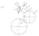
- a coating unit of a sheet-fed rotary printing press consists of Essentially from a sheet guiding cylinder 1 (impression cylinder), which transports the sheet material in the conveying direction 6, one with the sheet guide cylinder 1 in contact bringable forme cylinder 2 which a printing form, e.g. a Flexographic printing plate or a rubber blanket, carries, and a metering system 5.
- the metering system 5 preferably has at least one Circulation system for the circulation of coating fluid.
- the metering system 5 is through a screened applicator roller 3 and one with this applicator roller 3 chambered doctor blade system 4 formed, the application roller 3 with the forme cylinder 2 in a contact zone 13 is in functional connection.
- the metering system 5 is the metering system 5 as a two-roll mill with one with the forme cylinder 2 in the contact zone 13 coupled application roller 3 and one Metering roller 7 formed.
- the rollers 3.7 form a common one Roll nip 12 with a reservoir 8 one from above fed coating fluids.
- the metering system is shown in FIG. 3 5 as a scoop roller mill with a forme cylinder 2 in the contact zone 13 coupled applicator roller 3 and one in a reservoir 10 for immersing the coating fluid Scoop roller 9.
- the scoop roller 9 is with the applicator roller 3 in contact in a nip 12.
- At least the applicator roller 3 of the metering system 5 is in Direction of rotation on the lateral surface of at least one plating device 11 after the contact zone 13 and / or a nip 12, in which or a tear or a split of coating fluid has occurred on the lateral surface of the Applicator roller 3 adjustable and preferably adjacent adjacent assigned.
- the plating device 11 extends essentially parallel over a full roll width of Applicator roller 3.
- the application roller is in the direction of rotation 3 in front of a contact zone 13 or a nip 12 in the / in which tearing or splitting of coating fluid there is at least one plating device 11 the lateral surface of the applicator roller 3 can be turned on and off in parallel is arranged.
- the plating device 11 is assigned to the application roller 3, which is preferably connected to a chambered doctor blade system 4 is.
- the application roller 3 preferably has one Screening and the doctor blade system 4 has inside the chamber on another plating device 11, which on the application roller 3 is on and off.
- the plating device 11 is preferably by means of a Force F on the outer surface of the application roller 3, alternatively also a metering or scoop roller 7.9, on or off.
- a uniform one is preferred Surface pressure across the roller width of the applicator roller 3 or the metering or scoop roller 7.9, on the after Contact zone 13 remaining (remaining) coating fluid applicable.
- the Applicator roller 3 alternatively the metering or scoop roller 7.9, the plating device 11 in its direction tangent or can be turned on or off in secant shape on the lateral surface.
- Such a plating device 11 is preferably by a extending across the roll width, in the direction of rotation of the Applicator roller 3, preferably tangential (alternatively secant) positively employed plating element 14, which is detachably received in a holder 15 and in Axis direction across the entire roll width, at least parallel to the outer surface of the applicator roller 3, extends.
- the Bracket 15 of the plating element 14 is preferably in one swivel joint 16 arranged in the frame and supported on both sides, preferably pivotable about the axis of the hinge 16 stored.
- the plating element is 14 or the plating device 11 by means of at least one frame-side supported, preferably adjustable compression spring in functional connection.
- the plating element 14 is preferably loaded by a force F.
- Alternatives are instead of a compression spring, for example pneumatically workable cylinder or other force F generating agents can be used.
- the plating device 11 by using the dead weight with the assigned Roller 3, 7, 9, at least with the application roller 3, in functional connection, without a shearing effect on the lateral surface or to generate the remaining coating fluid.
- the plating device 11 (alternative the plating element 14) also with a minimal distance to the lateral surface of the roller 3, 7, 9, at least to the applicator roller 3, arranged to achieve a flat surface topography.
- the free end of the plating element 14 preferably ends on a surface normal (tangent point or secant point) the assigned roller 3,7,9, at least the applicator roller 3.
- the plating element 14 slightly tangential in the direction of rotation of the application roller 3 beyond their outer surface, tearing off Avoid coating fluid.
- the plating device 11 levels the uneven surface topography of the on the outer surface of the applicator roller 3 after the Contact zone 13 (of applicator roller 3 and forme cylinder 2) remaining remaining coating fluid before the remaining Coating fluid with the in the doctor blade system 4 or Roll nip 12 newly applied coating fluid in contact comes.
- plating device 11 is not limited to an application roller 3 with or without screening. Rather, the arrangement of plating devices 11 can also be implemented on further parts of the metering system 5. The arrangement of further plating devices 11 (in addition to at least one plating device 11 on the application roller 3) can preferably be implemented in the metering roller 7 or the scoop roller 9. The arrangement and design of the respective plating device 11 is analogous to the plating device 11 assigned to the applicator roller 3.
- an arrangement of at least one plating device 11 that can be turned on or off on the metering roller 7 or the scoop roller 9 in its direction of rotation can also be realized.
- At least one plating device 11 is assigned to the applicator roller 3 and the applicator roller 3 is functionally connected to a metering roller 7 and the two rollers 3, 7 form a nip 12 for receiving a reservoir 8 of coating fluid.
- a further plating device is arranged in parallel on the lateral surface of the metering roller 7.
- At least one plating device 11 is assigned to the applicator roller 3 and the applicator roller 3 is functionally connected to a scoop roller 9 immersed in a reservoir 10 and the two rollers 3,9 form a nip 12.
- the scoop roller 9 is in the direction of rotation a plating device 11 is arranged in parallel to the roll nip 12 on the lateral surface of the scoop roll 9 and can be removed.
- the respective plating device 11 is arranged in the direction of rotation of the metering roller 7 or the scoop roller 9 in its direction tangent-shaped or secant-shaped on the lateral surface of the respective roller 7,9 on and off.
- a plating device 11 In training with chambered doctor blade system 4 is in addition to Plating device 11 on the application roller 3 a plating device 11 also within the chamber of the doctor blade system 4 arranged.
- the plating device preferably supports 11 in this training the filling of the wells screened applicator roller 3 and prevents the penetration of Air bubbles in the wells.
- a further plating device 11 of the application roller 3 assigned and in the direction of rotation of this application roller 3 after the contact zone 13 with the forme cylinder 2 and in front of the nip 12 arranged.
- the plating device 11 can also be immersed in the reservoir 8. So that is additionally a calming of the flow in the reservoir 8 or Roll gap 12 achievable.
- the mode of operation is as follows: depending on the metering system 5 used, the coating fluid supplied, for example a lacquer, is located in the doctor blade system 4 or in the nip 12. In the direction of rotation of the application roller 3, the coating fluid is metered onto the outer surface and fed to the contact zone 13. In this contact zone 13, coating fluid is torn off according to the principle of ink splitting (lacquer splitting), so that a layer of a defined thickness of the coating fluid remains as the remaining coating fluid on the application roller 3 and a film of coating fluid in a defined layer thickness is transferred to the forme cylinder 2.
- ink splitting lacquer splitting
- the rest lies in the direction of rotation after the contact zone 13 Coating fluid in the form of an uneven surface topography of peaks, peaks and valleys on the lateral surface of the Application roller 3 before.
- the applicator roller now passes in the direction of rotation 3 which are preferably tangent-shaped or secant-shaped adjustable plating device 11, which change the shape (plastic shape) of the tips, tips and the Valleys.
- the plating device 11 lies through that Dead weight or with a defined force "floating" on the outer surface (with coating fluid) or in a slight distance to the outer surface to achieve arranged on a flat surface topography.
- the subject of the invention assumes that in Direction of rotation of a roller carrying a coating fluid 3,7,9 before and / or after a contact zone 13 or one Roll nip 12 in which a tear or splitting takes place the coating fluid on the outer surface of these rollers 3,7,9 leveled by means of at least one plating device 11 becomes.
- a leveling in front of the contact zone 13 or the nip 12 of the coating fluid preferably paint, can be carried out.
Landscapes
- Engineering & Computer Science (AREA)
- Mechanical Engineering (AREA)
- Coating Apparatus (AREA)
- Ink Jet (AREA)
- Electrophotography Configuration And Component (AREA)
- Inking, Control Or Cleaning Of Printing Machines (AREA)
Abstract
Description
Gemäß DE 39 41 571 A1 ist ein Dosiersystem bekannt, bei dem die in den Vorratsbehälter eintauchende Schöpfwalze im Reversebetrieb antreibbar ist, wobei zur Schöpfwalze ein Rakel als zusätzliche Dosierstelle angestellt ist.
Beispielsweise liegt bei einer Auftragwalze, nach der Spaltung des Beschichtungsfluides (Auftrennen der Beschichtungsfluidschicht) in einer Kontaktzone mit einem Formzylinder durch Abreißen des Beschichtungsfluides, z.B. Lack, insbesondere beim fadenförmigen Abreißen, keine gleichmäßige Verteilung des Beschichtungsfluides über die Walzenbreite betrachtet vor, sondern eine unebene Oberflächentopographie des restlichen Beschichtungsfluides, z.B. des Restlackes, auf der Mantelfläche der Auftragwalze.
Vorteilhaft bei der plastischen Formgebung durch eine Plattiereinrichtung ist es, dass das Beschichtungsfluid keiner Abscherwirkung (Scher- bzw. Zerteilwirkung) unterliegt, da eine Abscherwirkung wiederum zu einem ungewollten Abreißen von Beschichtungsfluid und damit zu einer unebenen Oberflächentopographie führt.
Beispielsweise ist zur Erzielung einer ebenen Oberflächentopographie ein Druckluft bzw. Blasluft auf die Mantelfläche der das Beschichtungsfluid führenden Walze einbringendes Luftrakel oder ein auf das Beschichtungsfluid gerichtetes Ultraschallschwingsystem einsetzbar, um eine plastische Formgebung zu erzielen.
- Fig. 1
- die Anordnung eines Dosiersystems mit Kammerrakelsystem,
- Fig. 2
- die Anordnung eines Dosiersystems als Zweiwalzenwerk,
- Fig. 3
- die Anordnung eines Dosiersystems als Schöpfwalzenwerk.
Die Anordnung und Ausbildung der jeweiligen Plattiereinrichtung 11 ist analog zu der der Auftragwalze 3 zugeordneten Plattiereinrichtung 11.
Dabei ist wenigstens eine Plattiereinrichtung 11 der Auftragwalze 3 zugeordnet und die Auftragwalze 3 ist mit einer Dosierwalze 7 in Funktionsverbindung und die beiden Walzen 3,7 bilden einen Walzenspalt 12 zur Aufnahme eines Reservoirs 8 von Beschichtungsfluid. In Weiterbildung ist nach dem Walzenspalt 12 in Drehrichtung der Dosierwalze 7 eine weitere Plattiereinrichtung an die Mantelfläche der Dosierwalze 7 parallel an- und abstellbar angeordnet.
Dabei ist in Drehrichtung der Dosierwalze 7 oder der Schöpfwalze 9 die jeweilige Plattiereinrichtung 11 in ihrer Richtung tangentenförmig oder sekantenförmig an die Mantelfläche der jeweiligen Walze 7,9 an- und abstellbar angeordnet.
In Drehrichtung der Auftragwalze 3 wird das Beschichtungsfluid auf die Mantelfläche dosiert aufgetragen und der Kontaktzone 13 zugeführt. In dieser Kontaktzone 13 erfolgt nach dem Prinzip der Farbspaltung (Lackspaltung) ein Abriss von Beschichtungsfluid, so dass eine Schicht definierter Dicke des Beschichtungsfluides als restliches Beschichtungsfluid auf der Auftragwalze 3 verbleibt und ein Film von Beschichtungsfluid in definierter Schichtdicke auf den Formzylinder 2 übertragen wird.
- 1
- Bogenführungszylinder
- 2
- Formzylinder
- 3
- Auftragwalze
- 4
- Kammerrakelsystem
- 5
- Dosiersystem
- 6
- Förderrichtung
- 7
- Dosierwalze
- 8
- Reservoir
- 9
- Schöpfwalze
- 10
- Vorratsbehälter
- 11
- Plattiereinrichtung
- 12
- Walzenspalt
- 13
- Kontaktzone
- 14
- Plattierelement
- 15
- Halterung
- 16
- Drehgelenk
- F
- Kraft
Claims (17)
- Dosiersystem für eine Beschichtungseinheit, insbesondere für ein Lackwerk, in einer Druckmaschine, mit wenigstens einem Formzylinder und einer mit dem Formzylinder in Funktionsverbindung stehenden Auftragwalze als Teil des Dosiersystems und zumindest einer Zuführung für ein Beschichtungsfluid,
dadurch gekennzeichnet, dass in Drehrichtung zumindest der Auftragwalze (3) nach einer Kontaktzone (13) oder einem Walzenspalt (12) in der / in dem ein Abreißen oder eine Spaltung von Beschichtungsfluid erfolgt ist wenigstens eine Plattiereinrichtung (11) an die Mantelfläche der Auftragwalze (3) parallel an- und abstellbar angeordnet ist. - Dosiersystem nach Anspruch 1,
dadurch gekennzeichnet, dass in Drehrichtung der Auftragwalze (3) vor einer Kontaktzone (13) oder einem Walzenspalt (12) in der / in dem ein Abreißen oder eine Spaltung von Beschichtungsfluid erfolgt wenigstens eine Plattiereinrichtung (11) an die Mantelfläche der Auftragwalze (3) parallel an- und abstellbar angeordnet ist. - Dosiersystem nach wenigstens Anspruch 1,
dadurch gekennzeichnet, dass in Drehrichtung der Auftragwalze (3) die Plattiereinrichtung (11) tangentenförmig oder sekantenfömig an die Mantelfläche der Auftragwalze (3) an- und abstellbar angeordnet ist. - Dosiersystem nach wenigstens Anspruch 1,
dadurch gekennzeichnet, dass eine Plattiereinrichtung (11) der Auftragwalze (3) zugeordnet ist, welche mit einem Kammerrakelsystem (4) in Funktionsverbindung ist. - Dosiersystem nach wenigstens Anspruch 1 und 4,
dadurch gekennzeichnet, dass die Auftragwalze (3) eine Rasterung aufweist und das Kammerrakelsystem (4) im Inneren der Kammer eine weitere Plattiereinrichtung (11) aufweist, welche an die Auftragwalze (3) an- und abstellbar ist. - Dosiersystem nach wenigstens Anspruch 1,
dadurch gekennzeichnet, dass eine Plattiereinrichtung (11) der Auftragwalze (3) zugeordnet ist, dass die Auftragwalze (3) mit einer Dosierwalze (7) in Funktionsverbindung ist und die Walzen (3,7) einen Walzenspalt (12) zur Aufnahme eines Reservoirs (8) von Beschichtungsfluid bilden. - Dosiersystem nach wenigstens Anspruch 1 und 6,
dadurch gekennzeichnet, dass in Drehrichtung der Dosierwalze (7) nach dem Walzenspalt (12) eine Plattiereinrichtung (11) an die Mantelfläche der Dosierwalze (7) parallel an- und abstellbar angeordnet ist. - Dosiersystem nach wenigstens Anspruch 1,
dadurch gekennzeichnet, dass eine Plattiereinrichtung (11) der Auftragwalze (3) zugeordnet ist und dass die Auftragwalze (3) mit einer in einen Vorratsbehälter (10) eintauchenden Schöpfwalze (9) in Funktionsverbindung ist und die Walzen (3,9) einen Walzenspalt (12) bilden. - Dosiersystem nach wenigstens Anspruch 1 und 8,
dadurch gekennzeichnet, dass in Drehrichtung der Schöpfwalze (9) vor dem Walzenspalt (12) eine Plattiereinrichtung (11) an die Mantelfläche der Schöpfwalze (9) parallel an- und abstellbar angeordnet ist. - Dosiersystem nach wenigstens Anspruch 6 und 8,
dadurch gekennzeichnet, dass in Drehrichtung der Dosierwalze (7) oder der Schöpfwalze (9) die jeweilige Plattiereinrichtung (11) in ihrer Richtung tangentenförmig oder sekantenfömig an die Mantelfläche der jeweiligen Walze (7,9) an- und abstellbar angeordnet ist. - Dosiersystem nach wenigstens Anspruch 1,
dadurch gekennzeichnet, dass die Plattiereinrichtung (12) mittels einer Kraft (F) an die Mantelfläche der Walze (3,7,9) anstellbar ist. - Dosiersystem nach wenigstens Anspruch 1,
dadurch gekennzeichnet, dass mittels der Plattiereinrichtung (12) eine gleichmäßige Flächenpressung über die Breite der Walze (3,7,9) aufbringbar ist. - Dosiersystem nach wenigstens Anspruch 1,
dadurch gekennzeichnet, dass die Plattiereinrichtung (12) in Drehrichtung der Walze (3,7,9) ein Plattierelement (14) aufweist, welches sich über die gesamte Walzenbreite erstreckt und in einer Halterung (15) lösbar angeordnet ist. - Dosiersystem nach wenigstens Anspruch 1 und 13,
dadurch gekennzeichnet, dass die Halterung (15) in einem gestellfesten Drehgelenk (16) beidseitig gelagert ist. - Dosiersystem nach wenigstens Anspruch 1 und 13,
dadurch gekennzeichnet, dass das Plattierelement (14) mit einer gestellseitig abgestützen Druckfeder in Funktionsverbindung ist. - Dosiersystem nach wenigstens Anspruch 1 und 13,
dadurch gekennzeichnet, dass ein freies Ende des Plattierelementes (14) tangentenförmig oder sekantenförmig an der Mantelfläche einer Walze (3,7,9,) in einem Tangenten- oder Sekantenpunkt endet. - Dosiersystem nach wenigstens Anspruch 1 und 13,
dadurch gekennzeichnet, dass ein freies Ende des Plattierelementes (14) in einem geringfügigen Abstand zur Mantelfläche der Walze (3,7,9) endet.
Applications Claiming Priority (2)
| Application Number | Priority Date | Filing Date | Title |
|---|---|---|---|
| DE10020512 | 2000-04-26 | ||
| DE10020512A DE10020512A1 (de) | 2000-04-26 | 2000-04-26 | Dosiersystem für eine Beschichtungseinheit in einer Druckmaschine |
Publications (3)
| Publication Number | Publication Date |
|---|---|
| EP1149700A2 true EP1149700A2 (de) | 2001-10-31 |
| EP1149700A3 EP1149700A3 (de) | 2005-03-16 |
| EP1149700B1 EP1149700B1 (de) | 2008-03-05 |
Family
ID=7640030
Family Applications (1)
| Application Number | Title | Priority Date | Filing Date |
|---|---|---|---|
| EP01109264A Expired - Lifetime EP1149700B1 (de) | 2000-04-26 | 2001-04-14 | Dosiersystem für eine Beschichtungseinheit in einer Druckmaschine |
Country Status (3)
| Country | Link |
|---|---|
| EP (1) | EP1149700B1 (de) |
| AT (1) | ATE388016T1 (de) |
| DE (2) | DE10020512A1 (de) |
Family Cites Families (9)
| Publication number | Priority date | Publication date | Assignee | Title |
|---|---|---|---|---|
| GB1267947A (en) * | 1969-10-30 | 1972-03-22 | Metal Box Co Ltd | Improvements in inking apparatus for printing machines |
| JPS59142148A (ja) * | 1983-02-03 | 1984-08-15 | Komori Printing Mach Co Ltd | 印刷物ニス塗り装置 |
| JPS62113551A (ja) * | 1985-11-13 | 1987-05-25 | Mitsubishi Heavy Ind Ltd | 平版印刷機の湿し装置 |
| DE3643936A1 (de) * | 1986-05-05 | 1987-11-12 | Polygraph Leipzig | Vorrichtung zum abheben einer changierenden brueckenwalze |
| DD282663A5 (de) * | 1988-03-25 | 1990-09-19 | Polygraph Leipzig | Auftragwerk fuer druckmaschinen |
| DD278551A1 (de) * | 1988-12-27 | 1990-05-09 | Polygraph Leipzig | Verfahren und einrichtung zum verarbeiten von spezialfarben in bogenoffsetdruckmaschinen |
| US6435086B1 (en) * | 1995-05-04 | 2002-08-20 | Howard W. DeMoore | Retractable inking/coating apparatus having ferris movement between printing units |
| DE19734100C5 (de) * | 1997-08-07 | 2007-08-09 | Koenig & Bauer Aktiengesellschaft | Druckturm einer Druckmaschine |
| US6076463A (en) * | 1998-03-13 | 2000-06-20 | Heidelberger Druckmaschinen Ag | Ink metering device and method of metering ink |
-
2000
- 2000-04-26 DE DE10020512A patent/DE10020512A1/de not_active Ceased
-
2001
- 2001-04-14 AT AT01109264T patent/ATE388016T1/de not_active IP Right Cessation
- 2001-04-14 EP EP01109264A patent/EP1149700B1/de not_active Expired - Lifetime
- 2001-04-14 DE DE50113678T patent/DE50113678D1/de not_active Expired - Lifetime
Also Published As
| Publication number | Publication date |
|---|---|
| DE50113678D1 (de) | 2008-04-17 |
| EP1149700B1 (de) | 2008-03-05 |
| EP1149700A3 (de) | 2005-03-16 |
| DE10020512A1 (de) | 2001-11-15 |
| ATE388016T1 (de) | 2008-03-15 |
Similar Documents
| Publication | Publication Date | Title |
|---|---|---|
| EP1097813B1 (de) | Bogenrotationsdruckmaschine mit Druckeinheiten für den Mehrfarbendruck und wenigstens einer Beschichtungseinheit | |
| EP0453910B1 (de) | Kammerrakel | |
| DE2950025A1 (de) | Mit wasser oder einem gemisch aus wasser und alkohol arbeitendes feuchtwerk fuer offset-druckmaschinen | |
| DE3505598A1 (de) | Spuelfarbwerk mit geteilter farbkammerrakel | |
| DE19729985C2 (de) | Vorrichtung zum Lackieren von Bedruckstoffen in einem Offsetdruckwerk einer Rotationsdruckmaschine | |
| EP0749368A1 (de) | Mehrfarbenrollenrotationsdruckmaschine für akzidenzdruck | |
| DE3329331A1 (de) | Druckwerk mit kurzem farbwerk | |
| EP0635366B1 (de) | Verfahren und Einrichtung zum Aufbringen eines flüssigen Mediums auf einen Bedruckstoff in Offsetdruckmaschinen | |
| DE3217569A1 (de) | Verfahren und vorrichtung zum dosieren der farbe bei offsetdruckmaschinen | |
| DE19934441A1 (de) | Vorrichtung zum direkten oder indirekten Auftragen eines flüssigen oder pastösen Auftragsmediums auf eine laufende Materialbahn, insbesondere aus Papier oder Karton | |
| AT397635B (de) | Dosiervorrichtung eines farbwerkes einer druckmaschine | |
| EP1278637B1 (de) | Dosiersystem zum einfärben von walzen in einer druckmaschine | |
| DE3334470C2 (de) | Farbwerk für eine Rotationsdruckmaschine | |
| EP0657282B1 (de) | Farbwerk | |
| EP0441220A2 (de) | Feuchtwerk | |
| EP1534522B1 (de) | Farbwerke von rotationsdruckmaschinen | |
| EP1149700B1 (de) | Dosiersystem für eine Beschichtungseinheit in einer Druckmaschine | |
| EP0387485B1 (de) | Vorrichtung zum Umstellen der zweiten (oberen) Zwischenwalze eines ein Farbwerk mit einem Feuchtwerk verbindenden Zwischenwalzenpaares | |
| DE3225564A1 (de) | Lackierwerk fuer eine mit eindruckwerk ausgeruestete offsetdruckmaschine | |
| EP1149696B1 (de) | Offsetdruckwerk für eine Druckmaschine | |
| EP4026696B1 (de) | Verfahren und vorrichtung zur erstellung eines flachbettsiebdruckes | |
| EP1389523A1 (de) | Beschichtungseinrichtung für eine Verarbeitungsmaschine | |
| EP1442884B1 (de) | Verfahren für einen stabilen Maschinenlauf an Druckeinheiten einer Rotationsdruckmaschine für den Betrieb mit teilbreitem Bedruckstoff | |
| EP1279500A2 (de) | Verfahren und Vorrichtung zum Dosieren eines flüssigen Mediums in einer Verarbeitungsmaschine | |
| EP1624106B1 (de) | Auftragsvorrichtung |
Legal Events
| Date | Code | Title | Description |
|---|---|---|---|
| PUAI | Public reference made under article 153(3) epc to a published international application that has entered the european phase |
Free format text: ORIGINAL CODE: 0009012 |
|
| AK | Designated contracting states |
Kind code of ref document: A2 Designated state(s): AT BE CH CY DE DK ES FI FR GB GR IE IT LI LU MC NL PT SE TR |
|
| AX | Request for extension of the european patent |
Free format text: AL;LT;LV;MK;RO;SI |
|
| PUAL | Search report despatched |
Free format text: ORIGINAL CODE: 0009013 |
|
| AK | Designated contracting states |
Kind code of ref document: A3 Designated state(s): AT BE CH CY DE DK ES FI FR GB GR IE IT LI LU MC NL PT SE TR |
|
| AX | Request for extension of the european patent |
Extension state: AL LT LV MK RO SI |
|
| 17P | Request for examination filed |
Effective date: 20050211 |
|
| AKX | Designation fees paid |
Designated state(s): AT BE CH CY DE DK ES FI FR GB GR IE IT LI LU MC NL PT SE TR |
|
| GRAP | Despatch of communication of intention to grant a patent |
Free format text: ORIGINAL CODE: EPIDOSNIGR1 |
|
| GRAS | Grant fee paid |
Free format text: ORIGINAL CODE: EPIDOSNIGR3 |
|
| GRAA | (expected) grant |
Free format text: ORIGINAL CODE: 0009210 |
|
| AK | Designated contracting states |
Kind code of ref document: B1 Designated state(s): AT BE CH CY DE DK ES FI FR GB GR IE IT LI LU MC NL PT SE TR |
|
| REG | Reference to a national code |
Ref country code: GB Ref legal event code: FG4D Free format text: NOT ENGLISH |
|
| REG | Reference to a national code |
Ref country code: CH Ref legal event code: EP |
|
| REG | Reference to a national code |
Ref country code: IE Ref legal event code: FG4D Free format text: LANGUAGE OF EP DOCUMENT: GERMAN |
|
| REF | Corresponds to: |
Ref document number: 50113678 Country of ref document: DE Date of ref document: 20080417 Kind code of ref document: P |
|
| RAP2 | Party data changed (patent owner data changed or rights of a patent transferred) |
Owner name: MANROLAND AG |
|
| PG25 | Lapsed in a contracting state [announced via postgrant information from national office to epo] |
Ref country code: ES Free format text: LAPSE BECAUSE OF FAILURE TO SUBMIT A TRANSLATION OF THE DESCRIPTION OR TO PAY THE FEE WITHIN THE PRESCRIBED TIME-LIMIT Effective date: 20080616 Ref country code: FI Free format text: LAPSE BECAUSE OF FAILURE TO SUBMIT A TRANSLATION OF THE DESCRIPTION OR TO PAY THE FEE WITHIN THE PRESCRIBED TIME-LIMIT Effective date: 20080305 |
|
| NLV1 | Nl: lapsed or annulled due to failure to fulfill the requirements of art. 29p and 29m of the patents act | ||
| REG | Reference to a national code |
Ref country code: IE Ref legal event code: FD4D |
|
| BERE | Be: lapsed |
Owner name: MAN ROLAND DRUCKMASCHINEN A.G. Effective date: 20080430 |
|
| PG25 | Lapsed in a contracting state [announced via postgrant information from national office to epo] |
Ref country code: PT Free format text: LAPSE BECAUSE OF FAILURE TO SUBMIT A TRANSLATION OF THE DESCRIPTION OR TO PAY THE FEE WITHIN THE PRESCRIBED TIME-LIMIT Effective date: 20080805 Ref country code: NL Free format text: LAPSE BECAUSE OF FAILURE TO SUBMIT A TRANSLATION OF THE DESCRIPTION OR TO PAY THE FEE WITHIN THE PRESCRIBED TIME-LIMIT Effective date: 20080305 Ref country code: SE Free format text: LAPSE BECAUSE OF FAILURE TO SUBMIT A TRANSLATION OF THE DESCRIPTION OR TO PAY THE FEE WITHIN THE PRESCRIBED TIME-LIMIT Effective date: 20080605 |
|
| PG25 | Lapsed in a contracting state [announced via postgrant information from national office to epo] |
Ref country code: MC Free format text: LAPSE BECAUSE OF NON-PAYMENT OF DUE FEES Effective date: 20080430 |
|
| REG | Reference to a national code |
Ref country code: CH Ref legal event code: PL |
|
| EN | Fr: translation not filed | ||
| PLBE | No opposition filed within time limit |
Free format text: ORIGINAL CODE: 0009261 |
|
| STAA | Information on the status of an ep patent application or granted ep patent |
Free format text: STATUS: NO OPPOSITION FILED WITHIN TIME LIMIT |
|
| PG25 | Lapsed in a contracting state [announced via postgrant information from national office to epo] |
Ref country code: LI Free format text: LAPSE BECAUSE OF NON-PAYMENT OF DUE FEES Effective date: 20080430 Ref country code: DK Free format text: LAPSE BECAUSE OF FAILURE TO SUBMIT A TRANSLATION OF THE DESCRIPTION OR TO PAY THE FEE WITHIN THE PRESCRIBED TIME-LIMIT Effective date: 20080305 Ref country code: IE Free format text: LAPSE BECAUSE OF FAILURE TO SUBMIT A TRANSLATION OF THE DESCRIPTION OR TO PAY THE FEE WITHIN THE PRESCRIBED TIME-LIMIT Effective date: 20080305 Ref country code: CH Free format text: LAPSE BECAUSE OF NON-PAYMENT OF DUE FEES Effective date: 20080430 |
|
| 26N | No opposition filed |
Effective date: 20081208 |
|
| GBPC | Gb: european patent ceased through non-payment of renewal fee |
Effective date: 20080605 |
|
| PG25 | Lapsed in a contracting state [announced via postgrant information from national office to epo] |
Ref country code: BE Free format text: LAPSE BECAUSE OF NON-PAYMENT OF DUE FEES Effective date: 20080430 |
|
| PG25 | Lapsed in a contracting state [announced via postgrant information from national office to epo] |
Ref country code: FR Free format text: LAPSE BECAUSE OF FAILURE TO SUBMIT A TRANSLATION OF THE DESCRIPTION OR TO PAY THE FEE WITHIN THE PRESCRIBED TIME-LIMIT Effective date: 20081226 |
|
| PG25 | Lapsed in a contracting state [announced via postgrant information from national office to epo] |
Ref country code: GB Free format text: LAPSE BECAUSE OF NON-PAYMENT OF DUE FEES Effective date: 20080605 |
|
| PG25 | Lapsed in a contracting state [announced via postgrant information from national office to epo] |
Ref country code: IT Free format text: LAPSE BECAUSE OF FAILURE TO SUBMIT A TRANSLATION OF THE DESCRIPTION OR TO PAY THE FEE WITHIN THE PRESCRIBED TIME-LIMIT Effective date: 20080305 |
|
| PG25 | Lapsed in a contracting state [announced via postgrant information from national office to epo] |
Ref country code: CY Free format text: LAPSE BECAUSE OF FAILURE TO SUBMIT A TRANSLATION OF THE DESCRIPTION OR TO PAY THE FEE WITHIN THE PRESCRIBED TIME-LIMIT Effective date: 20080305 |
|
| PG25 | Lapsed in a contracting state [announced via postgrant information from national office to epo] |
Ref country code: LU Free format text: LAPSE BECAUSE OF NON-PAYMENT OF DUE FEES Effective date: 20080414 |
|
| PG25 | Lapsed in a contracting state [announced via postgrant information from national office to epo] |
Ref country code: TR Free format text: LAPSE BECAUSE OF FAILURE TO SUBMIT A TRANSLATION OF THE DESCRIPTION OR TO PAY THE FEE WITHIN THE PRESCRIBED TIME-LIMIT Effective date: 20080305 |
|
| PGFP | Annual fee paid to national office [announced via postgrant information from national office to epo] |
Ref country code: AT Payment date: 20100415 Year of fee payment: 10 |
|
| PG25 | Lapsed in a contracting state [announced via postgrant information from national office to epo] |
Ref country code: GR Free format text: LAPSE BECAUSE OF FAILURE TO SUBMIT A TRANSLATION OF THE DESCRIPTION OR TO PAY THE FEE WITHIN THE PRESCRIBED TIME-LIMIT Effective date: 20080606 |
|
| PGFP | Annual fee paid to national office [announced via postgrant information from national office to epo] |
Ref country code: DE Payment date: 20110421 Year of fee payment: 11 |
|
| REG | Reference to a national code |
Ref country code: AT Ref legal event code: MM01 Ref document number: 388016 Country of ref document: AT Kind code of ref document: T Effective date: 20110414 |
|
| PG25 | Lapsed in a contracting state [announced via postgrant information from national office to epo] |
Ref country code: AT Free format text: LAPSE BECAUSE OF NON-PAYMENT OF DUE FEES Effective date: 20110414 |
|
| REG | Reference to a national code |
Ref country code: DE Ref legal event code: R081 Ref document number: 50113678 Country of ref document: DE Owner name: MANROLAND SHEETFED GMBH, DE Free format text: FORMER OWNER: MANROLAND AG, 63075 OFFENBACH, DE Effective date: 20120509 |
|
| REG | Reference to a national code |
Ref country code: DE Ref legal event code: R119 Ref document number: 50113678 Country of ref document: DE Effective date: 20121101 |
|
| PG25 | Lapsed in a contracting state [announced via postgrant information from national office to epo] |
Ref country code: DE Free format text: LAPSE BECAUSE OF NON-PAYMENT OF DUE FEES Effective date: 20121101 |