EP1147894A1 - Druckwerkszylinder - Google Patents
Druckwerkszylinder Download PDFInfo
- Publication number
- EP1147894A1 EP1147894A1 EP01107712A EP01107712A EP1147894A1 EP 1147894 A1 EP1147894 A1 EP 1147894A1 EP 01107712 A EP01107712 A EP 01107712A EP 01107712 A EP01107712 A EP 01107712A EP 1147894 A1 EP1147894 A1 EP 1147894A1
- Authority
- EP
- European Patent Office
- Prior art keywords
- printing unit
- cylinder
- printing
- unit cylinder
- diameter
- Prior art date
- Legal status (The legal status is an assumption and is not a legal conclusion. Google has not performed a legal analysis and makes no representation as to the accuracy of the status listed.)
- Granted
Links
- 238000007639 printing Methods 0.000 title claims abstract description 51
- 239000000835 fiber Substances 0.000 claims abstract description 10
- 239000000463 material Substances 0.000 claims abstract description 10
- 239000004033 plastic Substances 0.000 claims abstract description 3
- 239000004753 textile Substances 0.000 claims abstract description 3
- 239000011358 absorbing material Substances 0.000 claims description 19
- 238000007645 offset printing Methods 0.000 claims description 5
- 230000002745 absorbent Effects 0.000 abstract 1
- 239000002250 absorbent Substances 0.000 abstract 1
- 238000013016 damping Methods 0.000 description 5
- 238000010521 absorption reaction Methods 0.000 description 4
- 244000144992 flock Species 0.000 description 3
- 239000002390 adhesive tape Substances 0.000 description 2
- 238000010276 construction Methods 0.000 description 1
- 238000000034 method Methods 0.000 description 1
- 230000003319 supportive effect Effects 0.000 description 1
Images


Classifications
-
- B—PERFORMING OPERATIONS; TRANSPORTING
- B41—PRINTING; LINING MACHINES; TYPEWRITERS; STAMPS
- B41F—PRINTING MACHINES OR PRESSES
- B41F27/00—Devices for attaching printing elements or formes to supports
- B41F27/10—Devices for attaching printing elements or formes to supports for attaching non-deformable curved printing formes to forme cylinders
- B41F27/105—Devices for attaching printing elements or formes to supports for attaching non-deformable curved printing formes to forme cylinders for attaching cylindrical printing formes
-
- B—PERFORMING OPERATIONS; TRANSPORTING
- B41—PRINTING; LINING MACHINES; TYPEWRITERS; STAMPS
- B41P—INDEXING SCHEME RELATING TO PRINTING, LINING MACHINES, TYPEWRITERS, AND TO STAMPS
- B41P2213/00—Arrangements for actuating or driving printing presses; Auxiliary devices or processes
- B41P2213/40—Auxiliary devices or processes associated with the drives
- B41P2213/44—Noise reduction
Definitions
- the present invention relates to a printing unit cylinder for sound absorption in Printing machines, in particular in web-fed rotary printing machines, according to the preamble of claim 1 and claim 6.
- Sleeve-shaped printing forms or blankets also known as printing sleeves are used in a large number of printing processes.
- Offset printing are e.g. B. known as blankets designed printing sleeves, and also in Printing sleeves are used for flexographic printing.
- These sleeves are usually under the Influence of air openings formed in the outer surface of the cylinder escaping compressed air is pushed axially onto the respective cylinder. Through the Compressed air expands the sleeve to push it onto the cylinder or pull it off from the cylinder to facilitate. However, the outgoing compressed air sometimes creates a unwanted whistling or similar noise.
- US 5,215,213 is a sleeve-shaped rubber blanket with one on the inside of the Blanket positionable damping ring described.
- the damping ring dampens the vibrations of the sleeve caused by the compressed air flow and reduced to this Way the resulting noise.
- the blanket is axially on a blanket cylinder with a continuous outer surface, in which air openings are formed and which has an oblique edge surface.
- the sound-absorbing material is on a section of the Arranged outer surface of the printing unit cylinder, so that there is none on the printing sleeve itself sound-absorbing material must be provided. In this way the sound can too be dampened when removing and sliding on the pressure sleeve.
- the sound absorbing material preferably contacts the pressure sleeve during the axial opening and closing.
- the sound absorbing material can e.g. B. consist of flock tape.
- This material is used e.g. B. manufactured by Rolf Meyer GmbH and is available in the USA via International Knife and Saw Inc. available.
- the material can e.g. b. 2 mm to 3 mm thick and 16 mm wide and preferably has a layer of adhesive tape and one prior to attachment to the cylinder removable backstrip.
- the flock tape or loop tape includes z. Legs Backing layer and fibers, which, for. B. are glued to the carrier layer.
- the fibers can be textile fibers, plastic fibers or natural fibers and have a short length of e.g. B. 0.5 mm to 5 mm.
- a preferred, suitable for sound absorption Material is in particular a hook band or loop band Tape material.
- the outer surface of the cylinder preferably has a first at its free end Section with a first diameter, the free end of which in one drive-side frame overhung end of the cylinder is opposite. Furthermore, the outer surface preferably has a second section with a second Diameter, the first diameter preferably being smaller than the second Diameter is. The second section preferably contacts an inner surface of the Sleeve. This construction of the cylinder with two different diameters allows easier positioning of the sleeve on the cylinder, since the section with the smaller first diameter can serve as a guide for the sleeve.
- the Air openings can be arranged in a third section of the outer surface.
- An alternative embodiment of a printing group cylinder according to the invention a free end and an outer surface that has a plurality of air holes, which conduct air to the outer surface in such a way that a pressure sleeve axially on the Printing unit cylinder that can be pushed on and removed from it comprises according to the invention a roughened section on the outer surface at the free end of the printing unit cylinder, which dampens the sound generated by the air flowing out.
- free end is used in the present application for the end of the cylinder which lies opposite the end which is supported on the fly.
- the free end can be supported during production printing.
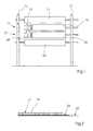
- Fig. 1 is a schematic representation of an offset printing press with a Printing unit cylinder according to the invention, which has an operator-side frame 10, a drive-side frame 12 and a first plate cylinder 14 and a second Includes plate cylinder 24 which between the operator side frame 10 and the drive-side frame 12 is mounted.
- the printing press further comprises a first blanket cylinder 16 and one second blanket cylinders 26, each at one end in the drive-side frame 12 and at its other end z. B. in bearings in the operator-side frame 10 arranged doors are detachably mounted. The doors can be opened so that one Opening is created through which a rubber blanket sleeve can be pulled off axially. in the When the doors are open, the blanket cylinders 16, 26 can be found on the drive side Frame 12 overhung and parked by the adjacent cylinders To create space for pushing on or pulling off the rubber blanket.
- the blanket cylinders 16, 26 are in the open state of the doors at their free Ends 17, 27 not supported. At the free ends 17, 27 is on the outer surface Rubber blankets each have a sound-absorbing material 18, 28, which is preferably runs in strips around the entire circumference of the blanket cylinder 16.
- the sound absorbing material is on the before Cylinder 16 in the form of a strip 31, which has an outer layer of sound-absorbing Material 18 includes, e.g. B. from the Rolf flock tape available from Knife and Saw, Inc. Meyer GmbH.
- the strip 31 further comprises a layer of adhesive tape and one removable back strip 33. After pulling back strip 33, strip 31 manually positioned at the free end of a cylinder.
- the blanket cylinder 16 comprises an outer surface 36 with a first section 37, the diameter d of which is smaller is than the diameter e of a second section 38. B. um 5 mm smaller than the diameter e. In this case, there is between the sections 37 and 38 a height difference of 2.5 mm, which is determined by an inclined section 39 is bridged.
- the first section 37 can also be designed in stages and several Have diameters that are smaller than the diameter e.
- an annular groove 40 may be formed, in which air openings 41, 42 and 43 are arranged, which a pulling or pulling a sleeve 50 on the blanket cylinder 16th generate supportive air pressure.
- the annular groove 40 can of course more than-three air openings, for. B. eight air openings are formed his.
- the air openings do not have to have a circular cross section, but rather can have a rectangular or otherwise non-circular cross-section be trained.
- the air openings 41, 42, 43 are preferably directly on the Surface 38 formed.
- the sound-absorbing material 18 contacts, for. B. with the fibers shown in Fig. 3, preferably an inner surface of the sleeve 50. However, this is not absolutely necessary. With a difference of 2.5 mm between section 38 and section 37 can use both 3mm thick and 2mm thick sound absorbing material be, whereby the 3 mm thick material creates a contact. Contacting the Inner surface of the sleeve 50 through the sound absorbing material 18 is preferred and facilitates the pulling and pulling of the sleeve 50, since a higher air pressure between Cylinder 16 and sleeve 50 are formed by the air supply to the air openings 41, 42, 43.
- Another possible sound absorbing material is e.g. B. hook tape or Loop tape, such as. B. is used in commercially available Velcro closures.
- fleece-like material can also be used for sound absorption.
- Fig. 4 shows an alternative embodiment of the present invention in which the free End 17 of the cylinder 16 has a roughened sound-absorbing section 80 which generates multiple sound reflections, which means that when air flows out of the Air openings 41, 42, 43 resulting sound is damped.
- the roughened sound-absorbing section 80 is preferably thread-shaped.
Landscapes
- Printing Plates And Materials Therefor (AREA)
- Photoreceptors In Electrophotography (AREA)
- Lubrication Of Internal Combustion Engines (AREA)
- Glass Compositions (AREA)
Abstract
Description
Die Merkmale der vorliegenden Erfindung werden in der folgenden Beschreibung bevorzugter Ausführungsbeispiele im Zusammenhang mit den beigefügten, nachstehend aufgeführten Zeichnungen näher erläutert.
- Fig. 1
- eine schematische Darstellung einer Offsetdruckmaschine mit einem erfindungsgemäßen Druckwerkszylinder;
- Fig. 2
- eine Art von schalldämpfendem Material, das bei der in Fig. 1 gezeigten Ausführungsform eingesetzt werden kann;
- Fig. 3
- eine Seitenansicht einer Druckmaschine mit einem erfindungsgemäßen Druckwerkszylinder; und
- Fig. 4
- eine Druckmaschine mit einer alternativen Ausführungsform eines erfindungsgemäßen Druckwerkszylinders.
- 10
- bedienerseitiger Rahmen
- 12
- antriebsseitiger Rahmen
- 14
- erster Plattenzylinder
- 16
- erster Gummituchzylinder
- 17
- freies Ende
- 18
- schalldämpfendes Material
- 24
- zweiter Plattenzylinder
- 26
- zweiter Gummituchzylinder
- 27
- freies Ende
- 28
- schalldämpfendes Material
- 31
- Streifen
- 32
- Schicht
- 33
- abziehbarer Rückstreifen
- 36
- Außenfläche
- 37
- erster Abschnitt
- 38
- zweiter Abschnitt
- 39
- geneigter Abschnitt
- 40
- Ringnut
- 41, 42, 43
- Luftöffnungen
- 50
- hülsenförmiges Gummituch/hülsenförmige Druckform
- 80
- aufgerauter schalldämpfender Abschnitt
- d
- Durchmesser
- e
- Durchmesser
Claims (9)
- Druckwerkszylinder (16, 26), insbesondere Formzylinder oder Übertragungszylinder, mit einem freien Ende (17, 27), wobei die Außenfläche (36) des Druckwerkszylinders (16, 26) eine Vielzahl von Luftlöchern (41, 42, 43) aufweist, welche Luft in der Weise an die Außenfläche (36) leiten, dass eine Druckhülse (50), insbesondere eine Gummituchhülse oder eine Druckformhülse, axial auf den Druckwerkszylinder (16, 26) aufschiebbar und von diesem abziehbar ist,
gekennzeichnet durch
ein schalldämpfendes Material (18, 28), das an einem Abschnitt (37) der Außenfläche (36) angeordnet ist. - Druckwerkszylinder nach Anspruch 1,
dadurch gekennzeichnet, dass das schalldämpfende Material (18) die Druckhülse (50) während des axialen Abziehens und/oder des axialen Aufschiebens der Druckhülse (50) kontaktiert. - Druckwerkszylinder nach Anspruch 1 oder 2,
dadurch gekennzeichnet, dass das schalldämpfende Material (18) aus einer Trägerschicht und Fasern, insbesondere kurz geschnittenen Textil- oder Kunststofffasern, besteht. - Druckwerkszylinder nach Anspruch 1 oder 2,
dadurch gekennzeichnet, dass das schalldämpfende Material (18) aus Hakenmaterial oder Schlaufenmaterial besteht. - Druckwerkszylinder nach einem der vorhergehenden Ansprüche,
dadurch gekennzeichnet, dass der Abschnitt (37) an einem freien Ende (17, 27) des Zylinders (16, 26) angeordnet ist und einen ersten Durchmesser (d) aufweist, und dass die Außenfläche (36) einen zweiten Abschnitt (38) aufweist, der einen zweiten Durchmesser (e) aufweist, wobei der erste Durchmesser (d) kleiner als der zweite Durchmesser (e) ist. - Druckwerkszylinder (16, 26) mit einem freien Ende (17, 27), wobei die Außenfläche (36) des Druckwerkszylinders (16, 26) eine Vielzahl von Luftlöchern (41, 42, 43) aufweist, welche Luft in der Weise an die Außenfläche (36) leiten, dass eine Druckhülse (50) axial auf den Druckwerkszylinder (16, 26) aufschiebbar und von diesem abziehbar ist,
dadurch gekennzeichnet, dass die Außenfläche (36) am freien Ende (17, 27) des Druckwerkszylinders (16, 26) einen aufgerauten Abschnitt (80) umfasst. - Druckwerkszylinder nach Anspruch 6,
dadurch gekennzeichnet, dass der aufgeraute Abschnitt (80) einen ersten Durchmesser (d) aufweist und die Außenfläche (36) einen zweiten Abschnitt (38) mit einem zweiten Durchmesser (e) aufweist, wobei der erste Durchmesser (d) kleiner als der zweite Durchmesser (e) ist. - Druckwerkszylinder nach Anspruch 6 oder 7,
dadurch gekennzeichnet, dass der aufgeraute Abschnitt (80) gewindeförmig ausgebildet ist. - Druckmaschine, insbesondere Rotations-Offsetdruckmaschine,
gekennzeichnet durch
einen Druckwerkszylinder nach einem der Ansprüche 1 bis 8.
Applications Claiming Priority (2)
| Application Number | Priority Date | Filing Date | Title |
|---|---|---|---|
| US552094 | 2000-04-19 | ||
| US09/552,094 US6347586B1 (en) | 2000-04-19 | 2000-04-19 | Method and device for reducing printing sleeve noise |
Publications (2)
| Publication Number | Publication Date |
|---|---|
| EP1147894A1 true EP1147894A1 (de) | 2001-10-24 |
| EP1147894B1 EP1147894B1 (de) | 2005-11-23 |
Family
ID=24203908
Family Applications (1)
| Application Number | Title | Priority Date | Filing Date |
|---|---|---|---|
| EP01107712A Expired - Lifetime EP1147894B1 (de) | 2000-04-19 | 2001-03-30 | Druckwerkszylinder |
Country Status (5)
| Country | Link |
|---|---|
| US (2) | US6347586B1 (de) |
| EP (1) | EP1147894B1 (de) |
| JP (1) | JP2001347630A (de) |
| AT (1) | ATE310637T1 (de) |
| DE (2) | DE50108129D1 (de) |
Families Citing this family (5)
| Publication number | Priority date | Publication date | Assignee | Title |
|---|---|---|---|---|
| US7107907B2 (en) * | 2001-01-22 | 2006-09-19 | Goss International Americas, Inc. | Flow-restricted printing cylinder for a removable printing sleeve |
| US6732648B1 (en) * | 2003-05-05 | 2004-05-11 | Day International Inc. | Printing blanket sleeve having sound dampening feature |
| US6938548B1 (en) | 2004-04-30 | 2005-09-06 | Eastman Kodak Company | Printing sleeve noise reducer |
| DE102011106886A1 (de) | 2011-07-07 | 2013-01-10 | Manroland Web Systems Gmbh | Druckwerkszylinder und hülsenförmiger Zylinderaufzug für einen Druckwerkszylinder |
| CN107001877B (zh) | 2014-10-13 | 2022-10-14 | 艾利丹尼森公司 | 可焊接的和减振硅氧烷粘合剂 |
Citations (1)
| Publication number | Priority date | Publication date | Assignee | Title |
|---|---|---|---|---|
| US5215013A (en) * | 1992-07-07 | 1993-06-01 | Heidelberg Harris Inc. | Printing blanket with noise attenuation |
Family Cites Families (8)
| Publication number | Priority date | Publication date | Assignee | Title |
|---|---|---|---|---|
| US1984115A (en) * | 1933-03-24 | 1934-12-11 | American Brass Co | Built-up print roll and method of making |
| US2987994A (en) * | 1958-08-18 | 1961-06-13 | Thomas K Allison | Mandrel and cylinder for gravure printing |
| US3739722A (en) * | 1971-08-13 | 1973-06-19 | Gross Instr Co | Print roll and mounting means |
| JPS5163708A (de) * | 1974-09-26 | 1976-06-02 | Emu Ei Batsukuree Engureibingu | |
| DE4106062C1 (de) * | 1991-02-27 | 1992-06-04 | Man Roland Druckmaschinen Ag, 6050 Offenbach, De | |
| US5601020A (en) * | 1993-01-22 | 1997-02-11 | Heidelberger Druckmaschinen Ag | Apparatus for reducing procession of a tubular printing sleeve |
| DE4342159C2 (de) * | 1993-12-10 | 1997-04-10 | Roland Man Druckmasch | Formzylinder für eine hülsenförmige Druckform |
| JP3575861B2 (ja) * | 1995-03-14 | 2004-10-13 | 大日本印刷株式会社 | オフセット印刷版、オフセット印刷機の版胴、オフセット印刷機及びオフセット印刷版の製造方法 |
-
2000
- 2000-04-19 US US09/552,094 patent/US6347586B1/en not_active Expired - Lifetime
-
2001
- 2001-03-30 AT AT01107712T patent/ATE310637T1/de not_active IP Right Cessation
- 2001-03-30 DE DE50108129T patent/DE50108129D1/de not_active Expired - Lifetime
- 2001-03-30 DE DE10115877A patent/DE10115877A1/de not_active Withdrawn
- 2001-03-30 EP EP01107712A patent/EP1147894B1/de not_active Expired - Lifetime
- 2001-04-17 JP JP2001118778A patent/JP2001347630A/ja active Pending
- 2001-11-28 US US09/997,027 patent/US6634294B2/en not_active Expired - Fee Related
Patent Citations (1)
| Publication number | Priority date | Publication date | Assignee | Title |
|---|---|---|---|---|
| US5215013A (en) * | 1992-07-07 | 1993-06-01 | Heidelberg Harris Inc. | Printing blanket with noise attenuation |
Also Published As
| Publication number | Publication date |
|---|---|
| US6347586B1 (en) | 2002-02-19 |
| ATE310637T1 (de) | 2005-12-15 |
| US20020035934A1 (en) | 2002-03-28 |
| EP1147894B1 (de) | 2005-11-23 |
| JP2001347630A (ja) | 2001-12-18 |
| DE50108129D1 (de) | 2005-12-29 |
| US6634294B2 (en) | 2003-10-21 |
| DE10115877A1 (de) | 2001-10-25 |
Similar Documents
| Publication | Publication Date | Title |
|---|---|---|
| EP0549936B1 (de) | Zwischen zwei Druckwerkseitenwänden gelagerter Übertragungszylinder mit einer auswechselbaren Hülse | |
| DE69815115T2 (de) | Druckmaschine mit veränderlichem abstellmechanismus | |
| DE4320924C2 (de) | Hülsenförmiges Druckgummituch mit Lärmdämpfung und seine Verwendung | |
| DE3902923C2 (de) | Bogenführungstrommel für Bogenrotationsdruckmaschinen | |
| DE102006030290B3 (de) | Druckwerk | |
| EP0858887B1 (de) | Druckmaschine | |
| DE4223908A1 (de) | Spannvorrichtung zum Spannen einer Druckplatte auf einem Plattenzylinder | |
| DE4404758C2 (de) | Verfahren und Vorrichtung zum Wechseln der Bespannung eines Zylinders einer Rollenrotationsdruckmaschine | |
| EP0119537A2 (de) | Papierbahnfangvorrichtung | |
| DE4308712B4 (de) | Druckmaschine | |
| EP1093914A2 (de) | Vorrichtung zum Abnehmen eines hülsenförmigen Gummituchs | |
| EP1225046A1 (de) | Druckzylinder zum Aufnehmen einer Druckhülse | |
| DE19753744A1 (de) | Walze für das rotative Bedrucken, Beschichten oder Prägen u.gl., insbesondere Druckwalze für den Flexo- oder Tiefdruck | |
| EP1147894B1 (de) | Druckwerkszylinder | |
| DE102006061452A1 (de) | Druckplattenkassette | |
| DE2701670A1 (de) | Offset-rotationsdruckmaschine | |
| DE3112775C2 (de) | Rotationsdruckmaschine in Reihenbauweise | |
| EP1568494A1 (de) | Vorrichtung zur Herstellung unterschiedlicher Druckbildlängen im Offsetdruck | |
| DE102004051323A1 (de) | Maschine zur Verarbeitung von Bedruckstoffbogen | |
| DE10066162B4 (de) | Druckwerk einer Rotationsdruckmaschine | |
| DE10249947A1 (de) | Druckwerk einer Rollenrotationsdruckmaschine für Zeitungsdruck | |
| DE19758453C2 (de) | Vorrichtung zum Befestigen einer Bespannung auf einem Druckwerkzylinder | |
| EP1099549A2 (de) | Vorrichtung und Verfahren zum Stützen von fliegend gelagerten Zylindern | |
| DE102005039782A1 (de) | System sowie ein Verfahren zum Vornehmen von Drucklängenwechseln | |
| DE3609934A1 (de) | Bohrwerkzeug mit austauschbarer foerderwendel |
Legal Events
| Date | Code | Title | Description |
|---|---|---|---|
| PUAI | Public reference made under article 153(3) epc to a published international application that has entered the european phase |
Free format text: ORIGINAL CODE: 0009012 |
|
| AK | Designated contracting states |
Kind code of ref document: A1 Designated state(s): AT BE CH CY DE DK ES FI FR GB GR IE IT LI LU MC NL PT SE TR |
|
| AX | Request for extension of the european patent |
Free format text: AL;LT;LV;MK;RO;SI |
|
| 17P | Request for examination filed |
Effective date: 20010906 |
|
| AKX | Designation fees paid |
Free format text: AT BE CH CY DE DK ES FI FR GB GR IE IT LI LU MC NL PT SE TR |
|
| RAP1 | Party data changed (applicant data changed or rights of an application transferred) |
Owner name: GOSS INTERNATIONAL AMERICAS, INC. |
|
| GRAP | Despatch of communication of intention to grant a patent |
Free format text: ORIGINAL CODE: EPIDOSNIGR1 |
|
| GRAS | Grant fee paid |
Free format text: ORIGINAL CODE: EPIDOSNIGR3 |
|
| GRAA | (expected) grant |
Free format text: ORIGINAL CODE: 0009210 |
|
| AK | Designated contracting states |
Kind code of ref document: B1 Designated state(s): AT BE CH CY DE DK ES FI FR GB GR IE IT LI LU MC NL PT SE TR |
|
| PG25 | Lapsed in a contracting state [announced via postgrant information from national office to epo] |
Ref country code: IE Free format text: LAPSE BECAUSE OF FAILURE TO SUBMIT A TRANSLATION OF THE DESCRIPTION OR TO PAY THE FEE WITHIN THE PRESCRIBED TIME-LIMIT Effective date: 20051123 Ref country code: FI Free format text: LAPSE BECAUSE OF FAILURE TO SUBMIT A TRANSLATION OF THE DESCRIPTION OR TO PAY THE FEE WITHIN THE PRESCRIBED TIME-LIMIT Effective date: 20051123 Ref country code: NL Free format text: LAPSE BECAUSE OF FAILURE TO SUBMIT A TRANSLATION OF THE DESCRIPTION OR TO PAY THE FEE WITHIN THE PRESCRIBED TIME-LIMIT Effective date: 20051123 |
|
| REG | Reference to a national code |
Ref country code: GB Ref legal event code: FG4D Free format text: NOT ENGLISH |
|
| REG | Reference to a national code |
Ref country code: CH Ref legal event code: EP |
|
| GBT | Gb: translation of ep patent filed (gb section 77(6)(a)/1977) | ||
| REF | Corresponds to: |
Ref document number: 50108129 Country of ref document: DE Date of ref document: 20051229 Kind code of ref document: P |
|
| REG | Reference to a national code |
Ref country code: IE Ref legal event code: FG4D Free format text: LANGUAGE OF EP DOCUMENT: GERMAN |
|
| PG25 | Lapsed in a contracting state [announced via postgrant information from national office to epo] |
Ref country code: DK Free format text: LAPSE BECAUSE OF FAILURE TO SUBMIT A TRANSLATION OF THE DESCRIPTION OR TO PAY THE FEE WITHIN THE PRESCRIBED TIME-LIMIT Effective date: 20060223 Ref country code: SE Free format text: LAPSE BECAUSE OF FAILURE TO SUBMIT A TRANSLATION OF THE DESCRIPTION OR TO PAY THE FEE WITHIN THE PRESCRIBED TIME-LIMIT Effective date: 20060223 Ref country code: GR Free format text: LAPSE BECAUSE OF FAILURE TO SUBMIT A TRANSLATION OF THE DESCRIPTION OR TO PAY THE FEE WITHIN THE PRESCRIBED TIME-LIMIT Effective date: 20060223 |
|
| PG25 | Lapsed in a contracting state [announced via postgrant information from national office to epo] |
Ref country code: ES Free format text: LAPSE BECAUSE OF FAILURE TO SUBMIT A TRANSLATION OF THE DESCRIPTION OR TO PAY THE FEE WITHIN THE PRESCRIBED TIME-LIMIT Effective date: 20060306 |
|
| PG25 | Lapsed in a contracting state [announced via postgrant information from national office to epo] |
Ref country code: AT Free format text: LAPSE BECAUSE OF NON-PAYMENT OF DUE FEES Effective date: 20060330 |
|
| PG25 | Lapsed in a contracting state [announced via postgrant information from national office to epo] |
Ref country code: BE Free format text: LAPSE BECAUSE OF NON-PAYMENT OF DUE FEES Effective date: 20060331 Ref country code: MC Free format text: LAPSE BECAUSE OF NON-PAYMENT OF DUE FEES Effective date: 20060331 Ref country code: LU Free format text: LAPSE BECAUSE OF NON-PAYMENT OF DUE FEES Effective date: 20060331 |
|
| PG25 | Lapsed in a contracting state [announced via postgrant information from national office to epo] |
Ref country code: PT Free format text: LAPSE BECAUSE OF FAILURE TO SUBMIT A TRANSLATION OF THE DESCRIPTION OR TO PAY THE FEE WITHIN THE PRESCRIBED TIME-LIMIT Effective date: 20060424 |
|
| NLV1 | Nl: lapsed or annulled due to failure to fulfill the requirements of art. 29p and 29m of the patents act | ||
| REG | Reference to a national code |
Ref country code: CH Ref legal event code: NV Representative=s name: KIRKER & CIE SA |
|
| ET | Fr: translation filed | ||
| REG | Reference to a national code |
Ref country code: IE Ref legal event code: FD4D |
|
| PLBE | No opposition filed within time limit |
Free format text: ORIGINAL CODE: 0009261 |
|
| STAA | Information on the status of an ep patent application or granted ep patent |
Free format text: STATUS: NO OPPOSITION FILED WITHIN TIME LIMIT |
|
| 26N | No opposition filed |
Effective date: 20060824 |
|
| BERE | Be: lapsed |
Owner name: GOSS INTERNATIONAL AMERICAS, INC. Effective date: 20060331 |
|
| PG25 | Lapsed in a contracting state [announced via postgrant information from national office to epo] |
Ref country code: TR Free format text: LAPSE BECAUSE OF FAILURE TO SUBMIT A TRANSLATION OF THE DESCRIPTION OR TO PAY THE FEE WITHIN THE PRESCRIBED TIME-LIMIT Effective date: 20051123 |
|
| PG25 | Lapsed in a contracting state [announced via postgrant information from national office to epo] |
Ref country code: CY Free format text: LAPSE BECAUSE OF FAILURE TO SUBMIT A TRANSLATION OF THE DESCRIPTION OR TO PAY THE FEE WITHIN THE PRESCRIBED TIME-LIMIT Effective date: 20051123 |
|
| PGFP | Annual fee paid to national office [announced via postgrant information from national office to epo] |
Ref country code: CH Payment date: 20100325 Year of fee payment: 10 |
|
| PGFP | Annual fee paid to national office [announced via postgrant information from national office to epo] |
Ref country code: GB Payment date: 20100326 Year of fee payment: 10 |
|
| PGFP | Annual fee paid to national office [announced via postgrant information from national office to epo] |
Ref country code: IT Payment date: 20110328 Year of fee payment: 11 Ref country code: FR Payment date: 20110331 Year of fee payment: 11 |
|
| PGFP | Annual fee paid to national office [announced via postgrant information from national office to epo] |
Ref country code: DE Payment date: 20110329 Year of fee payment: 11 |
|
| REG | Reference to a national code |
Ref country code: CH Ref legal event code: PL |
|
| GBPC | Gb: european patent ceased through non-payment of renewal fee |
Effective date: 20110330 |
|
| PG25 | Lapsed in a contracting state [announced via postgrant information from national office to epo] |
Ref country code: CH Free format text: LAPSE BECAUSE OF NON-PAYMENT OF DUE FEES Effective date: 20110331 Ref country code: LI Free format text: LAPSE BECAUSE OF NON-PAYMENT OF DUE FEES Effective date: 20110331 |
|
| PG25 | Lapsed in a contracting state [announced via postgrant information from national office to epo] |
Ref country code: GB Free format text: LAPSE BECAUSE OF NON-PAYMENT OF DUE FEES Effective date: 20110330 |
|
| REG | Reference to a national code |
Ref country code: FR Ref legal event code: ST Effective date: 20121130 |
|
| REG | Reference to a national code |
Ref country code: DE Ref legal event code: R119 Ref document number: 50108129 Country of ref document: DE Effective date: 20121002 |
|
| PG25 | Lapsed in a contracting state [announced via postgrant information from national office to epo] |
Ref country code: FR Free format text: LAPSE BECAUSE OF NON-PAYMENT OF DUE FEES Effective date: 20120402 |
|
| PG25 | Lapsed in a contracting state [announced via postgrant information from national office to epo] |
Ref country code: IT Free format text: LAPSE BECAUSE OF NON-PAYMENT OF DUE FEES Effective date: 20120330 |
|
| PG25 | Lapsed in a contracting state [announced via postgrant information from national office to epo] |
Ref country code: DE Free format text: LAPSE BECAUSE OF NON-PAYMENT OF DUE FEES Effective date: 20121002 |