EP1146536B1 - Verfahren zur Aufbereitung von Kathodenstrahlröhren - Google Patents
Verfahren zur Aufbereitung von Kathodenstrahlröhren Download PDFInfo
- Publication number
- EP1146536B1 EP1146536B1 EP20010303400 EP01303400A EP1146536B1 EP 1146536 B1 EP1146536 B1 EP 1146536B1 EP 20010303400 EP20010303400 EP 20010303400 EP 01303400 A EP01303400 A EP 01303400A EP 1146536 B1 EP1146536 B1 EP 1146536B1
- Authority
- EP
- European Patent Office
- Prior art keywords
- acid
- frit glass
- solution
- cathode ray
- funnel
- Prior art date
- Legal status (The legal status is an assumption and is not a legal conclusion. Google has not performed a legal analysis and makes no representation as to the accuracy of the status listed.)
- Expired - Lifetime
Links
Images

Classifications
-
- H—ELECTRICITY
- H01—ELECTRIC ELEMENTS
- H01J—ELECTRIC DISCHARGE TUBES OR DISCHARGE LAMPS
- H01J9/00—Apparatus or processes specially adapted for the manufacture, installation, removal, maintenance of electric discharge tubes, discharge lamps, or parts thereof; Recovery of material from discharge tubes or lamps
- H01J9/50—Repairing or regenerating used or defective discharge tubes or lamps
-
- H—ELECTRICITY
- H01—ELECTRIC ELEMENTS
- H01J—ELECTRIC DISCHARGE TUBES OR DISCHARGE LAMPS
- H01J9/00—Apparatus or processes specially adapted for the manufacture, installation, removal, maintenance of electric discharge tubes, discharge lamps, or parts thereof; Recovery of material from discharge tubes or lamps
- H01J9/52—Recovery of material from discharge tubes or lamps
-
- Y—GENERAL TAGGING OF NEW TECHNOLOGICAL DEVELOPMENTS; GENERAL TAGGING OF CROSS-SECTIONAL TECHNOLOGIES SPANNING OVER SEVERAL SECTIONS OF THE IPC; TECHNICAL SUBJECTS COVERED BY FORMER USPC CROSS-REFERENCE ART COLLECTIONS [XRACs] AND DIGESTS
- Y02—TECHNOLOGIES OR APPLICATIONS FOR MITIGATION OR ADAPTATION AGAINST CLIMATE CHANGE
- Y02W—CLIMATE CHANGE MITIGATION TECHNOLOGIES RELATED TO WASTEWATER TREATMENT OR WASTE MANAGEMENT
- Y02W30/00—Technologies for solid waste management
- Y02W30/50—Reuse, recycling or recovery technologies
- Y02W30/60—Glass recycling
-
- Y—GENERAL TAGGING OF NEW TECHNOLOGICAL DEVELOPMENTS; GENERAL TAGGING OF CROSS-SECTIONAL TECHNOLOGIES SPANNING OVER SEVERAL SECTIONS OF THE IPC; TECHNICAL SUBJECTS COVERED BY FORMER USPC CROSS-REFERENCE ART COLLECTIONS [XRACs] AND DIGESTS
- Y02—TECHNOLOGIES OR APPLICATIONS FOR MITIGATION OR ADAPTATION AGAINST CLIMATE CHANGE
- Y02W—CLIMATE CHANGE MITIGATION TECHNOLOGIES RELATED TO WASTEWATER TREATMENT OR WASTE MANAGEMENT
- Y02W30/00—Technologies for solid waste management
- Y02W30/50—Reuse, recycling or recovery technologies
- Y02W30/82—Recycling of waste of electrical or electronic equipment [WEEE]
Definitions
- the present invention relates to a method for recycling a cathode ray tube bulb.
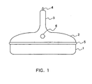
- cathode ray tubes such as for a color television, are primarily made of a glass panel 1 and a funnel 2.
- a neck 3 and an exhaust tube 4 are connected to each other at the tip of the funnel 2 on the opposite side to the panel 1.
- An anode button 6 for applying a high voltage to the dag coating described below is provided on the funnel 2.
- the inner surface of the glass panel 1 is coated with a fluorescent film, and the inner surface of the funnel 2 is coated with a dag coating having carbon black as the main component.
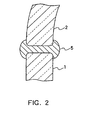
- a frit glass 5 is disposed between the sealing faces of the glass panel 1 and the funnel 2, and heated to ca. 450°C, thus crystallizing the frit glass 5 and fritting the glass panel 1 and the funnel 2 together.
- an electrode gun is sealed into the neck portion 3 of the funnel 2, the funnel is exhausted through the exhaust tube 4, and the electron gun is treated electrically, thus completing the color cathode ray tube.
- the manufacturing costs for a bulb made of a glass panel 1 and a funnel 2 make up a large part of the total cost for manufacturing a color cathode ray tube. For that reason, it is important to collect and reuse the bulbs that have turned defective during the manufacturing process and the bulbs from products that have turned defective, in order to drive down the manufacturing cost of the color cathode ray tube.
- the frit glass In order to separate the glass panel from the funnel, the frit glass has to be dissolved.
- the frit glass is dissolved with nitric acid (see, for example, JP H01(1989)-1942391A or JP H03(1991)-156830A).
- the concentration of the nitric acid is usually set to 10 to 15wt%.
- an ultrasonic wave generator is used in combination, so as to enhance the corrosion of the frit glass with the nitric acid.
- nitric acid is very harmful to the environment and the human body, it has to be handled with utmost care. Also, because of the high corrosivity of nitric acid, there is the danger that it corrodes the anode button of the funnel. When the anode button is corroded, the funnel cannot be reused. Furthermore, the corrosivity of the nitric acid is also a cause for expensive counter-measures against corrosion and maintenance fees for the various kinds of equipment, such as the ultrasonic wave generator.
- a method for recycling a cathode ray tube bulb comprising a panel and a funnel bonded together with a frit glass the method comprises separating the panel and the funnel, characterised in that: the cathode ray tube bulb is arranged such that the frit glass is immersed in the solution of an organic acid;, wherein at least a portion of the frit glass is dissolved by a solution of an organic acid by blowing the solution against the frit glass in the solution.
- the methods use an organic acid solution instead of nitric acid, so that it solves the problems caused by the high corrosivity of nitric acid.
- nitric acid instead of nitric acid
- the cathode ray tube bulb is arranged such that the frit glass is immersed in the organic acid solution, and to blow the organic acid solution against the frit glass in the organic acid solution.
- organic acid used in the present invention there is no particular limitation with regard to the organic acid used in the present invention, as long as it can dissolve a frit glass.
- suitable organic acids include carboxylic acids, such as at least one carboxylic acid selected from glycolic acid, maleic acid, malic acid, formic acid, lactic acid, acetic acid, dichloroacetic acid, and pyruvic acid.
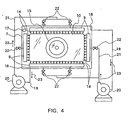
- a bulb supporting stand 16 is arranged at the bottom of a frit dissolution bath 7, which is filled with a predetermined amount of an aqueous organic acid solution 8.
- the bulb 10 is placed on the bulb supporting stand 16, with a weight 15 holding down the panel. In this situation, the entire frit glass 5 is submersed in the aqueous organic acid solution 8.
- Spray nozzles 9 are arranged in opposition to the frit glass 5.
- Aqueous organic solution is supplied to the nozzles 9 from a solution circulation system.
- the main elements of this solution circulation system are pipes 19 for connecting to the dissolution bath 7 with inlet ports 18, pumps 20 for taking in the solution from these pipes 19, pipes 21 for connecting the pumps 20 with the spray nozzles 9, and valves 22 in these pipes 21.
- the aqueous organic acid solution circulates through the solution circulation system in the direction indicated by the arrow 23, and is sprayed by the spray nozzles 9 on the frit glass 5 along the arrow directions denoted by the numeral 14.
- a heater 17 for controlling the temperature of the solution is placed in the dissolution bath 7. It is preferable that the temperature of the aqueous organic acid solution is maintained at ca. 35 to 45°C in order to sustain the dissolution amount of the frit glass.
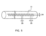
- the spray nozzles 9 for example a stainless steel pipe in which spraying holes 11 of predetermined diameter are formed along the longitudinal direction of the pipe.
- a frit glass dissolution test was performed.
- a 20wt% aqueous glycolic acid solution was used as the aqueous organic acid solution, and the overall circulation amount of the solution was set to 0.28m 3 /min.
- the temperature of the solution was kept at 40°C.
- the distance 12 between the spray nozzles 9 and the frit glass 5 was set to 15mm, and the distance 13 between the surface of the solution and the spray nozzles 9 was set to 20mm.
- holes 11 with a diameter 26 of 1mm are arranged in two rows in the longitudinal direction of a stainless steel tube, the holes of one row being arranged between the holes of the other row.
- the spacing 25 of the holes 11 in the longitudinal pipe direction is 5mm, and the spacing 24 of the holes 11 in the circumferential pipe direction is 2mm.
- the total circumference (total length) of the frit glass 5 in the cathode ray tube bulb used in this test was 207cm.
- the panel and the funnel that have been separated are reusable, they can be fastened together again with frit glass and reused in a bulb for a new cathode ray tube.
- a bulb for a cathode ray tube including at least one of the separated panel and funnel can be obtained.
- This embodiment illustrates only one specific embodiment of the present invention, and does not limit the technical scope of the present invention.
- the organic acid and its solvent there is no limitation with regard to the organic acid and its solvent, the configuration of the device, and the procedure for the recycling.
- the present invention solves the problems that occur when nitric acid is used by using an organic acid.
Landscapes
- Engineering & Computer Science (AREA)
- Manufacturing & Machinery (AREA)
- Manufacture Of Electron Tubes, Discharge Lamp Vessels, Lead-In Wires, And The Like (AREA)
- Processing Of Solid Wastes (AREA)
Claims (6)
- Verfahren zum Recyceln eines Kathodenstrahlröhrenkolbens, der eine Frontscheibe (1) und einen Trichter (2) umfasst, die durch ein Frittenglas (5) miteinander verbunden sind, wobei das Verfahren das Abtrennen der Frontscheibe (1) und des Trichters (2) umfasst,
dadurch gekennzeichnet, dass:wobei mindestens ein Anteil des Frittenglases (5) mit einer Lösung einer organischen Säure aufgelöst wird, indem die Lösung gegen das Frittenglas (5) in der Lösung getrieben wird.der Kathodenstrahlröhrenkolben so angeordnet ist, dass das Frittenglas (5) in die Lösung einer organischen Säure eingetaucht wird, - Verfahren nach Anspruch 1, wobei die organische Säure eine Karbonsäure ist.
- Verfahren nach Anspruch 2, wobei die Karbonsäure mindestens eine der Säuren ausgewählt aus Glykolsäure, Maleinsäure, Apfelsäure, Ameisensäure, Milchsäure, Essigsäure, Dichloressigsäure und Brenztraubensäure einschließt.
- Verfahren nach einem der Ansprüche 1 bis 3, wobei die Temperatur der Lösung 35 bis 45 °C ist.
- Verfahren nach einem der Ansprüche 1 bis 4, wobei die Frontscheibe (1) und der Trichter (2) durch Anwenden einer Spannung an einen Teilbereich, wo das Frittenglas (5) aufgelöst wurde, abgetrennt werden, nachdem ein Teil des Frittenglases (5) mit der Lösung aufgelöst wurde.
- Verfahren zum Herstellen eines Kathodenstrahlröhrenkolbens, das ein Verbinden einer Frontscheibe (1) und eines Trichters (2) mit einem Frittenglas (5) umfasst, wobei mindestens die Frontscheibe (1) oder der Trichter (2) durch einen Prozess hergestellt wird, der das Recyceln nach einem der Ansprüche 1 bis 5 einschließt.
Applications Claiming Priority (2)
| Application Number | Priority Date | Filing Date | Title |
|---|---|---|---|
| JP2000112552 | 2000-04-13 | ||
| JP2000112552A JP3729702B2 (ja) | 2000-04-13 | 2000-04-13 | ブラウン管用バルブの再生方法 |
Publications (2)
| Publication Number | Publication Date |
|---|---|
| EP1146536A1 EP1146536A1 (de) | 2001-10-17 |
| EP1146536B1 true EP1146536B1 (de) | 2005-07-20 |
Family
ID=18624703
Family Applications (1)
| Application Number | Title | Priority Date | Filing Date |
|---|---|---|---|
| EP20010303400 Expired - Lifetime EP1146536B1 (de) | 2000-04-13 | 2001-04-11 | Verfahren zur Aufbereitung von Kathodenstrahlröhren |
Country Status (7)
| Country | Link |
|---|---|
| US (1) | US6752675B2 (de) |
| EP (1) | EP1146536B1 (de) |
| JP (1) | JP3729702B2 (de) |
| KR (1) | KR100433447B1 (de) |
| CN (1) | CN1244124C (de) |
| DE (1) | DE60111992T2 (de) |
| MY (1) | MY124936A (de) |
Families Citing this family (8)
| Publication number | Priority date | Publication date | Assignee | Title |
|---|---|---|---|---|
| JP3475913B2 (ja) | 2000-06-09 | 2003-12-10 | 松下電器産業株式会社 | ガラスパネルとファンネルとの分離方法 |
| JP2003040646A (ja) * | 2001-07-27 | 2003-02-13 | Nippon Electric Glass Co Ltd | 陰極線管用ファンネルガラス |
| CN100367442C (zh) * | 2004-05-14 | 2008-02-06 | 清华大学 | 一种crt玻壳分离方法及其专用设备 |
| US20080056326A1 (en) * | 2006-08-21 | 2008-03-06 | Laserresearch (S) Pte Ltd | Process And Apparatus For Laser Selective Separation |
| CN101328010B (zh) * | 2008-07-11 | 2011-03-30 | 清华大学 | 一种crt玻壳热裂分离方法 |
| CN101357821B (zh) * | 2008-07-16 | 2011-05-11 | 清华大学 | 一种crt玻壳热裂分离设备 |
| CN101685740B (zh) * | 2008-09-28 | 2012-02-15 | 四川虹欧显示器件有限公司 | Pdp显示面板的再生方法和封接器件的分离方法 |
| US8668540B1 (en) * | 2012-09-14 | 2014-03-11 | ECS Refining, LLC | Method and apparatus for separating the glass panel from a cathode ray tube |
Family Cites Families (18)
| Publication number | Priority date | Publication date | Assignee | Title |
|---|---|---|---|---|
| DE299793C (de) | ||||
| JPH01194239A (ja) | 1988-01-26 | 1989-08-04 | Nec Corp | ブラウン管の再生方法 |
| JP2725211B2 (ja) | 1989-10-02 | 1998-03-11 | 日本電気硝子株式会社 | ガラス表面処理方法 |
| JPH03156830A (ja) | 1989-11-15 | 1991-07-04 | Toshiba Corp | カラーブラウン管のバルブ回収方法 |
| JP2710071B2 (ja) | 1989-12-14 | 1998-02-10 | 日本電気硝子株式会社 | ガラス表面処理方法 |
| DE4102886A1 (de) | 1991-01-31 | 1992-08-06 | Georg Van Eyk | Verfahren zur verringerung der abgabe von schwermetallen aus glaesern |
| DE4319364A1 (de) | 1993-06-11 | 1994-12-15 | Kloeckner Humboldt Deutz Ag | Verfahren zur Aufbereitung von Bildschirmröhren |
| JP3401841B2 (ja) * | 1993-07-09 | 2003-04-28 | ソニー株式会社 | Crtの分割方法、分割装置および再生処理方法 |
| JPH08133781A (ja) | 1994-11-09 | 1996-05-28 | Mitsui Toatsu Chem Inc | 低融点ガラスペースト |
| US6123876A (en) * | 1995-04-04 | 2000-09-26 | Canon Kabushiki Kaisha | Metal-containing composition for forming electron-emitting device |
| JP3690613B2 (ja) | 1995-05-17 | 2005-08-31 | 佐賀県 | 陶磁器 |
| DE19522962C2 (de) | 1995-06-15 | 2001-01-11 | Boehme Elektr Recycling Gmbh | Verfahren zur Aufbereitung von Bildröhrenglas |
| JP3156830B2 (ja) | 1995-06-20 | 2001-04-16 | 本田技研工業株式会社 | 面削用フライス装置 |
| DE19537277C1 (de) | 1995-10-06 | 1996-08-08 | Dornier Gmbh Lindauer | Frottierwebmaschine mit einer Florhöhenverstelleinrichtung |
| US5858616A (en) * | 1995-10-13 | 1999-01-12 | Hitachi Chemical Company, Ltd. | Photosensitive resin composition, photosensitive film and process for preparing fluorescent pattern using the same, and phosphor subjected to surface treatment and process for preparing the same |
| JP3122030B2 (ja) | 1996-04-10 | 2001-01-09 | 不二電機工業株式会社 | 集合表示灯 |
| JPH1167072A (ja) | 1997-08-25 | 1999-03-09 | Fujitsu Ltd | パターン形成方法 |
| KR100408492B1 (ko) | 1997-12-29 | 2004-03-26 | 이기원 | 전자부품의조립에사용하는열경화성유리층의제거방법 |
-
2000
- 2000-04-13 JP JP2000112552A patent/JP3729702B2/ja not_active Expired - Fee Related
-
2001
- 2001-04-09 US US09/829,304 patent/US6752675B2/en not_active Expired - Fee Related
- 2001-04-11 DE DE2001611992 patent/DE60111992T2/de not_active Expired - Fee Related
- 2001-04-11 EP EP20010303400 patent/EP1146536B1/de not_active Expired - Lifetime
- 2001-04-12 KR KR10-2001-0019601A patent/KR100433447B1/ko not_active Expired - Fee Related
- 2001-04-12 MY MYPI20011758A patent/MY124936A/en unknown
- 2001-04-13 CN CNB011165863A patent/CN1244124C/zh not_active Expired - Fee Related
Also Published As
| Publication number | Publication date |
|---|---|
| CN1317817A (zh) | 2001-10-17 |
| MY124936A (en) | 2006-07-31 |
| KR20010098555A (ko) | 2001-11-08 |
| CN1244124C (zh) | 2006-03-01 |
| US6752675B2 (en) | 2004-06-22 |
| DE60111992D1 (de) | 2005-08-25 |
| EP1146536A1 (de) | 2001-10-17 |
| JP2001297701A (ja) | 2001-10-26 |
| DE60111992T2 (de) | 2006-04-27 |
| US20030124943A1 (en) | 2003-07-03 |
| JP3729702B2 (ja) | 2005-12-21 |
| KR100433447B1 (ko) | 2004-05-28 |
Similar Documents
| Publication | Publication Date | Title |
|---|---|---|
| US6752675B2 (en) | Method for recycling cathode ray tube bulb | |
| EP0222948B1 (de) | Verfahren zum Trennen von Komponenten einer Kathodenstrahlröhre | |
| EP0222949B1 (de) | Entfernen von Überzügen von Kathodenstrahlröhren oder Teilen hiervon | |
| US8940229B2 (en) | Device for irradiating surfaces | |
| JPH10255817A (ja) | 電池の洗浄・乾燥方法 | |
| CN100367442C (zh) | 一种crt玻壳分离方法及其专用设备 | |
| JPH02268879A (ja) | 洗浄方法 | |
| JP2001307624A (ja) | シャドウマスクの洗浄方法、シャドウマスクの洗浄装置、シャドウマスク、および陰極線管 | |
| JPS6252415B2 (de) | ||
| KR930008614B1 (ko) | 직열형 캐소오드의 전착방법 및 그 장치 | |
| JPH11191375A (ja) | ブラウン管の回収処理方法およびその装置 | |
| KR100810196B1 (ko) | 시알티용 디스플레이 패널의 내면복합코팅막의 박리세정용조성물 | |
| KR19980023555A (ko) | 음극선관의 고주파 유도코일 결선방법 | |
| JPS62252038A (ja) | 陰極線管の光吸収層の再生方法 | |
| JPH0418195Y2 (de) | ||
| JPH0817348A (ja) | ブラウン管の製造方法 | |
| JPH08277476A (ja) | 内視鏡用部品及びその製造方法並びにその部品を用い た内視鏡 | |
| JPH02291640A (ja) | 陰極線管の耐電圧処理方法 | |
| JPH07155713A (ja) | ブラウン管の蛍光面の洗浄方法 | |
| IT9021822A1 (it) | Metodo di trattamento di un telaio per un elettrodo di selezione dei colori per un tubo a raggi catodici. | |
| KR950006919A (ko) | 브라운관용 넥크 튜브 세척 장치 및 방법 | |
| KR19980086063A (ko) | 컬러음극선관의 내압불량 제거방법 | |
| CN111725066A (zh) | 一种半导体表面去除氟杂质的方法 | |
| JPS6093735A (ja) | カラ−陰極線管用シヤドウマスクの再生方法 | |
| KR980008170U (ko) | 금속관의 내면 전해연마수단 |
Legal Events
| Date | Code | Title | Description |
|---|---|---|---|
| PUAI | Public reference made under article 153(3) epc to a published international application that has entered the european phase |
Free format text: ORIGINAL CODE: 0009012 |
|
| AK | Designated contracting states |
Kind code of ref document: A1 Designated state(s): AT BE CH CY DE DK ES FI FR GB GR IE IT LI LU MC NL PT SE TR Kind code of ref document: A1 Designated state(s): DE FR GB IT NL |
|
| AX | Request for extension of the european patent |
Free format text: AL;LT;LV;MK;RO;SI |
|
| 17P | Request for examination filed |
Effective date: 20010907 |
|
| AKX | Designation fees paid |
Free format text: DE FR GB IT NL |
|
| 17Q | First examination report despatched |
Effective date: 20040112 |
|
| GRAP | Despatch of communication of intention to grant a patent |
Free format text: ORIGINAL CODE: EPIDOSNIGR1 |
|
| RIN1 | Information on inventor provided before grant (corrected) |
Inventor name: AOKI, IKUKO Inventor name: MISHIMA, MASAKI Inventor name: OKADA, HIDEFUMI Inventor name: SASADA, JUICHI Inventor name: TOKIYASU, HIDEAKI Inventor name: SAIMOTO, KAZUO |
|
| GRAS | Grant fee paid |
Free format text: ORIGINAL CODE: EPIDOSNIGR3 |
|
| GRAA | (expected) grant |
Free format text: ORIGINAL CODE: 0009210 |
|
| RIN1 | Information on inventor provided before grant (corrected) |
Inventor name: AOKI, IKUKO Inventor name: MISHIMA, MASAKI Inventor name: OKADA, HIDEFUMI Inventor name: SASADA, JUICHI Inventor name: TOKIYASU, HIDEAKI Inventor name: SAIMOTO, KAZUO |
|
| AK | Designated contracting states |
Kind code of ref document: B1 Designated state(s): DE FR GB IT NL |
|
| PG25 | Lapsed in a contracting state [announced via postgrant information from national office to epo] |
Ref country code: NL Free format text: LAPSE BECAUSE OF FAILURE TO SUBMIT A TRANSLATION OF THE DESCRIPTION OR TO PAY THE FEE WITHIN THE PRESCRIBED TIME-LIMIT Effective date: 20050720 |
|
| REG | Reference to a national code |
Ref country code: GB Ref legal event code: FG4D |
|
| REF | Corresponds to: |
Ref document number: 60111992 Country of ref document: DE Date of ref document: 20050825 Kind code of ref document: P |
|
| NLV1 | Nl: lapsed or annulled due to failure to fulfill the requirements of art. 29p and 29m of the patents act | ||
| PGFP | Annual fee paid to national office [announced via postgrant information from national office to epo] |
Ref country code: GB Payment date: 20060404 Year of fee payment: 6 |
|
| ET | Fr: translation filed | ||
| PGFP | Annual fee paid to national office [announced via postgrant information from national office to epo] |
Ref country code: DE Payment date: 20060420 Year of fee payment: 6 |
|
| PGFP | Annual fee paid to national office [announced via postgrant information from national office to epo] |
Ref country code: FR Payment date: 20060425 Year of fee payment: 6 |
|
| PGFP | Annual fee paid to national office [announced via postgrant information from national office to epo] |
Ref country code: IT Payment date: 20060430 Year of fee payment: 6 |
|
| PLBE | No opposition filed within time limit |
Free format text: ORIGINAL CODE: 0009261 |
|
| STAA | Information on the status of an ep patent application or granted ep patent |
Free format text: STATUS: NO OPPOSITION FILED WITHIN TIME LIMIT |
|
| 26N | No opposition filed |
Effective date: 20060421 |
|
| GBPC | Gb: european patent ceased through non-payment of renewal fee |
Effective date: 20070411 |
|
| PG25 | Lapsed in a contracting state [announced via postgrant information from national office to epo] |
Ref country code: DE Free format text: LAPSE BECAUSE OF NON-PAYMENT OF DUE FEES Effective date: 20071101 |
|
| PG25 | Lapsed in a contracting state [announced via postgrant information from national office to epo] |
Ref country code: GB Free format text: LAPSE BECAUSE OF NON-PAYMENT OF DUE FEES Effective date: 20070411 |
|
| PG25 | Lapsed in a contracting state [announced via postgrant information from national office to epo] |
Ref country code: FR Free format text: LAPSE BECAUSE OF NON-PAYMENT OF DUE FEES Effective date: 20070430 |
|
| PG25 | Lapsed in a contracting state [announced via postgrant information from national office to epo] |
Ref country code: IT Free format text: LAPSE BECAUSE OF NON-PAYMENT OF DUE FEES Effective date: 20070411 |