EP1146206A2 - Abgas-Schalldämpfer in Mehrkammerbauweise - Google Patents
Abgas-Schalldämpfer in Mehrkammerbauweise Download PDFInfo
- Publication number
- EP1146206A2 EP1146206A2 EP01103818A EP01103818A EP1146206A2 EP 1146206 A2 EP1146206 A2 EP 1146206A2 EP 01103818 A EP01103818 A EP 01103818A EP 01103818 A EP01103818 A EP 01103818A EP 1146206 A2 EP1146206 A2 EP 1146206A2
- Authority
- EP
- European Patent Office
- Prior art keywords
- exhaust
- outlet
- exhaust gas
- shell
- silencer according
- Prior art date
- Legal status (The legal status is an assumption and is not a legal conclusion. Google has not performed a legal analysis and makes no representation as to the accuracy of the status listed.)
- Granted
Links
Images




Classifications
-
- F—MECHANICAL ENGINEERING; LIGHTING; HEATING; WEAPONS; BLASTING
- F01—MACHINES OR ENGINES IN GENERAL; ENGINE PLANTS IN GENERAL; STEAM ENGINES
- F01N—GAS-FLOW SILENCERS OR EXHAUST APPARATUS FOR MACHINES OR ENGINES IN GENERAL; GAS-FLOW SILENCERS OR EXHAUST APPARATUS FOR INTERNAL-COMBUSTION ENGINES
- F01N13/00—Exhaust or silencing apparatus characterised by constructional features
- F01N13/18—Construction facilitating manufacture, assembly, or disassembly
- F01N13/1872—Construction facilitating manufacture, assembly, or disassembly the assembly using stamp-formed parts or otherwise deformed sheet-metal
-
- F—MECHANICAL ENGINEERING; LIGHTING; HEATING; WEAPONS; BLASTING
- F01—MACHINES OR ENGINES IN GENERAL; ENGINE PLANTS IN GENERAL; STEAM ENGINES
- F01N—GAS-FLOW SILENCERS OR EXHAUST APPARATUS FOR MACHINES OR ENGINES IN GENERAL; GAS-FLOW SILENCERS OR EXHAUST APPARATUS FOR INTERNAL-COMBUSTION ENGINES
- F01N1/00—Silencing apparatus characterised by method of silencing
- F01N1/02—Silencing apparatus characterised by method of silencing by using resonance
-
- F—MECHANICAL ENGINEERING; LIGHTING; HEATING; WEAPONS; BLASTING
- F01—MACHINES OR ENGINES IN GENERAL; ENGINE PLANTS IN GENERAL; STEAM ENGINES
- F01N—GAS-FLOW SILENCERS OR EXHAUST APPARATUS FOR MACHINES OR ENGINES IN GENERAL; GAS-FLOW SILENCERS OR EXHAUST APPARATUS FOR INTERNAL-COMBUSTION ENGINES
- F01N1/00—Silencing apparatus characterised by method of silencing
- F01N1/02—Silencing apparatus characterised by method of silencing by using resonance
- F01N1/04—Silencing apparatus characterised by method of silencing by using resonance having sound-absorbing materials in resonance chambers
-
- F—MECHANICAL ENGINEERING; LIGHTING; HEATING; WEAPONS; BLASTING
- F01—MACHINES OR ENGINES IN GENERAL; ENGINE PLANTS IN GENERAL; STEAM ENGINES
- F01N—GAS-FLOW SILENCERS OR EXHAUST APPARATUS FOR MACHINES OR ENGINES IN GENERAL; GAS-FLOW SILENCERS OR EXHAUST APPARATUS FOR INTERNAL-COMBUSTION ENGINES
- F01N1/00—Silencing apparatus characterised by method of silencing
- F01N1/06—Silencing apparatus characterised by method of silencing by using interference effect
-
- F—MECHANICAL ENGINEERING; LIGHTING; HEATING; WEAPONS; BLASTING
- F01—MACHINES OR ENGINES IN GENERAL; ENGINE PLANTS IN GENERAL; STEAM ENGINES
- F01N—GAS-FLOW SILENCERS OR EXHAUST APPARATUS FOR MACHINES OR ENGINES IN GENERAL; GAS-FLOW SILENCERS OR EXHAUST APPARATUS FOR INTERNAL-COMBUSTION ENGINES
- F01N13/00—Exhaust or silencing apparatus characterised by constructional features
- F01N13/18—Construction facilitating manufacture, assembly, or disassembly
- F01N13/1838—Construction facilitating manufacture, assembly, or disassembly characterised by the type of connection between parts of exhaust or silencing apparatus, e.g. between housing and tubes, between tubes and baffles
- F01N13/1844—Mechanical joints
- F01N13/185—Mechanical joints the connection being realised by deforming housing, tube, baffle, plate, or parts thereof
-
- F—MECHANICAL ENGINEERING; LIGHTING; HEATING; WEAPONS; BLASTING
- F01—MACHINES OR ENGINES IN GENERAL; ENGINE PLANTS IN GENERAL; STEAM ENGINES
- F01N—GAS-FLOW SILENCERS OR EXHAUST APPARATUS FOR MACHINES OR ENGINES IN GENERAL; GAS-FLOW SILENCERS OR EXHAUST APPARATUS FOR INTERNAL-COMBUSTION ENGINES
- F01N13/00—Exhaust or silencing apparatus characterised by constructional features
- F01N13/18—Construction facilitating manufacture, assembly, or disassembly
- F01N13/1888—Construction facilitating manufacture, assembly, or disassembly the housing of the assembly consisting of two or more parts, e.g. two half-shells
-
- F—MECHANICAL ENGINEERING; LIGHTING; HEATING; WEAPONS; BLASTING
- F01—MACHINES OR ENGINES IN GENERAL; ENGINE PLANTS IN GENERAL; STEAM ENGINES
- F01N—GAS-FLOW SILENCERS OR EXHAUST APPARATUS FOR MACHINES OR ENGINES IN GENERAL; GAS-FLOW SILENCERS OR EXHAUST APPARATUS FOR INTERNAL-COMBUSTION ENGINES
- F01N2470/00—Structure or shape of exhaust gas passages, pipes or tubes
- F01N2470/14—Plurality of outlet tubes, e.g. in parallel or with different length
-
- F—MECHANICAL ENGINEERING; LIGHTING; HEATING; WEAPONS; BLASTING
- F01—MACHINES OR ENGINES IN GENERAL; ENGINE PLANTS IN GENERAL; STEAM ENGINES
- F01N—GAS-FLOW SILENCERS OR EXHAUST APPARATUS FOR MACHINES OR ENGINES IN GENERAL; GAS-FLOW SILENCERS OR EXHAUST APPARATUS FOR INTERNAL-COMBUSTION ENGINES
- F01N2490/00—Structure, disposition or shape of gas-chambers
- F01N2490/15—Plurality of resonance or dead chambers
- F01N2490/155—Plurality of resonance or dead chambers being disposed one after the other in flow direction
Definitions
- the invention relates to an exhaust gas silencer in a multi-chamber construction, in particular exhaust silencers of a passenger car, with an outer housing consisting of a upper and a lower half shell, an inner shell as well an internal exhaust duct through the exhaust silencer.
- Such an exhaust silencer is for example from DE 196 27 079.0 known. It has two inner half-shells, in which the internal exhaust gas routing is stamped and which the Form inner partitions of the chambers. Above the top horizontal partition is an absorption chamber and below a reflection chamber is provided in the lower partition. The inner half-shells are curved over a common one Edge section connected to the outer housing. The inner one Exhaust gas routing has an S-shape. So it's a comparative one Long internal exhaust path with a compact exhaust silencer intended.
- the invention has for its object an exhaust muffler to provide of the type mentioned, which as Rear silencer an optimal damping even in the low frequency Area and is still compact.
- the essence of the invention is that the exhaust gas routing at least one has a first curved outlet pipe, which has a first curved section has and its preferably rectilinear The outlet end is flush with the outer housing.
- the second curved outlet pipe also has one second curvature section and a second, preferably rectilinear Exit end, wherein the curvature sections of the first outlet pipe and the second outlet pipe in plan view are directed towards each other, and preferably in cross different heights in the exhaust silencer.
- an exhaust silencer With regard to the external dimension of an exhaust silencer a particularly large length of outlet pipes can be realized, if in a further aspect of the invention the exit ends of the first outlet pipe and the second outlet pipe on the outlet side of the exhaust silencer parallel and at a close distance from each other in a horizontal plane are arranged, and the inlet ends of the first outlet pipe and the second outlet pipe on the opposite The inlet side of the exhaust muffler is in the side inner corner areas of the exhaust silencer in one first reflection chamber.
- Such a configuration dampens an outlet pipe shape like two "mammoth teeth" during operation, especially the low-frequency humming tones according to the prior art in a passenger vehicle as special to be annoying.
- the silencer is nevertheless relatively small in size.
- the one that can be used as a rear silencer Exhaust muffler according to the invention thus has a Integrated outlet pipe extension straight through the training the curvature sections.
- the outlet pipes preferably have no jacket perforation.
- the outlet pipes can have a stepped widened end, where the ratio of the diameter of the outlet pipes to the diameter of the stepped, extended end of the outlet pipes can advantageously range from 40 to 52.
- a compact exhaust gas silencer according to the invention is in particular as a four-chamber shell silencer with integrated Outlet pipe extension provided.
- first and a second inner radial Partition formed in the interior of the exhaust silencer.
- the one assigned to the outlet side of the exhaust muffler second partition extends over the entire inner cross section of the exhaust silencer and is with the External housing firmly connected.
- an upper inner shell that extends to the second Partition extends and firmly connected to the second partition is also located on the inlet side of the exhaust silencer.
- the upper inner shell is preferably in one Shell fold of the upper and lower half-shell of the outer housing anchored.
- the first partition extends over the entire lower one Half-shell cross-section up to the upper inner shell and is in turn firmly connected to the upper inner shell.
- the one located on the inlet side of the exhaust silencer Space between the upper inner shell and the upper half shell of the outer housing to the second partition is preferred filled with sound absorbing material and thus forms one first absorption chamber.
- the one located on the outlet side of the exhaust silencer There is space between the second partition and the outer housing expediently also filled with a sound absorbent and in this way provides a second absorption chamber represents.
- the one located on the inlet side of the exhaust silencer Space between the upper inner shell and the lower half shell of the outer housing to the first partition is a Empty space and thus forms a first reflection chamber.
- a second reflection chamber is formed when the room between the upper inner shell and the lower half shell of the outer casing and between the first and the second Partition is also an empty space.
- empty space is understood to mean a space that has no sound absorbing material. It is understood that the outlet pipes mentioned at the beginning run in this "empty space" can, as well as other parts of the inner Exhaust gas routing, especially an inlet pipe.
- the exhaust gas guide preferably has a straight inlet pipe on the one on the outlet side of the exhaust silencer end located in the second absorption chamber located.
- the inlet pipe can be perforated at least partially on the jacket side and thereby with passages at least to the first reflection chamber and formed to the second reflection chamber his.
- the first and the second partition have through openings for the inlet pipe and the outlet pipes, the inlet pipe and the outlet pipes at least with the first partition are firmly connected, preferably also to the second Partition, at least in one variant.
- the first and the second partition as well as the upper inner shell have at least partial perforation sections.
- the inlet pipe may include an angled inlet that runs flush with the outer case.
- the inlet pipe in the second absorption chamber has a closed end and a jacket perforation in the area of the second absorption chamber.
- the inlet pipe in the second absorption chamber has an open end, which is coaxial and with circumferential spacing in an open on one side Deflection tube is arranged.
- the baffle is in the second absorption chamber arranged and in a breakthrough attached to the second partition such that the annular Outlet opening of the deflection tube into the second reflection chamber has.
- the annular outlet opening lie in the plane of the second partition.
- the deflecting tube can also be perforated on the shell side and thereby connected to the second absorption chamber via passages his. With the exception of the perforations are the second absorption chamber and also the aforementioned first absorption chamber completely closed and also sealed gas-tight. They effect the well-known buffer damping.
- the inlet pipe has a tapered, stepped end portion at least in the area of the deflection tube.
- the cross section of the stepped end portion of the inlet pipe preferably equal to the cross section of the annular outlet opening of the deflection pipe.
- the exhaust gas silencer attached to a vehicle underbody in such a way that the first and second absorption chambers in Point towards the vehicle underbody, then not only one good sound absorption in the direction of the vehicle interior achieved, but also good thermal insulation during operation Exhaust muffler towards the vehicle underbody.
- This is particularly of when a vehicle is traveling slowly Advantage, namely when the airstream is the top of the Exhaust silencer cannot cool sufficiently and nevertheless by the thermal insulation of the two according to the invention Absorption chambers the top on a comparatively low temperature level can be maintained.
- the invention in particular realized a rear silencer for a passenger car, which has an integrated tailpipe extension.
- Another particular advantage of the invention is the low muzzle sound level in silencer systems with extreme volume distribution between front silencer / middle silencer to rear silencer, for example in a ratio of 15 to 85.
- the invention further relates to an exhaust gas silencer a cup fold in the form of an angled circumferential fold and with two outer half-shells each with an edge as well at least one inner shell with a flat edge, the Edges of the outer half-shells angled on the outside and over the circumferential fold are interconnected and the flat Edge of the inner shell (s) between the edges of the outer half-shells is firmly clamped.
- the invention further relates to a method of manufacture of a aforementioned silencer.
- EP 0 664 380 A1 discloses a silencer of the aforementioned type
- the outer half-shells have curved edges, the one in the assembled state of a housing shell Form the clamping bead.
- the flat edge of the inner shell is dimensioned so that it just touches the wall of the housing shell and only held resiliently between the local clamping beads becomes.
- the clamping beads are already in the prefabrication of the outer half-shells.
- the embossing depth of the Clamping bead is predetermined by the thickness of the inner shell. The disadvantage is that the position and depth of the clamping bead in the embossing tool must be determined.
- the circumferential fold can only change the position and depth of the clamping bead in the same configuration and the inner shell only with be formed to a constant thickness that has no tolerances allows, you do not want to affect the clamping effect.
- the local clamping beads also do not allow sealing of the Inner shell opposite the outer half shells.
- the circumferential fold according to the invention characterizes through two different training courses on the entire circumferential length with the same basic constellation.
- the inner shell (s) opposite the outer half-shells and at least one other inner one Partition of the exhaust silencer is sealed.
- Part of it is a pure closure of the two outer half-shells.
- the inner shell can vary within certain limits Have thickness without the clamping and sealing effect of the inner shell and the outer half shells.
- the partial crimping of the inner shell (s) advantageously allows the formation of at least one additional chamber a shell silencer.
- the angled circumferential fold can preferably be downward be trained and a simply folded top edge have an upper outer half shell. This variant allows external fluid to drain off at the peripheral fold and therefore do not intrude into the interior of the silencer.
- the angled peripheral fold has in particular an upper one Counterbend or top counterbend.
- This variant is particularly advantageous for creating a larger area an effective biasing force or contact pressure of the flat Edges of the outer half-shells either directly against each other or indirectly against each other with the interposition of the flat Edges of the inner shell, with a good sealing effect in both cases even with different thicknesses of an inner shell given is.
- At least the outer half-shells and the angled peripheral fold can be double-walled, which is different Silencer variants with the same circumferential fold design enables.
- a lower outer half shell can have an inner bottom, which is turned up over a radius and sealingly bordered on the underside of the inner shell.
- an exhaust gas silencer 1 in Four-chamber design of a passenger car has an outer housing 2nd
- the outer housing 2 is composed of an upper half shell 3 and a lower half-shell 4 together in their horizontal Parting plane by means of a shell fold 25 with each other are firmly connected. In the shell fold 25 there is also a upper inner shell 5 attached. Through the exhaust silencer 1 extends an internal exhaust duct.
- the exhaust gas duct has two curved outlet pipes 9, 10, which are arranged inside the exhaust silencer 1.
- the first curved outlet pipe 9 is the left outlet pipe and has a first curvature section, the top view 2 is curved to the right.
- the exit end 27 is located in the left rear corner of the exhaust silencer 1.
- the first outlet pipe 9 extends from straight back into the interior of the muffler.
- the section of curvature describes an arc of 90 °.
- the entry section the outlet pipe 9 is again straight.
- the entry end 29 is approximately the right front corner of the muffler interior on the inlet side of the exhaust silencer.
- the exit end 27 runs flush with the outer housing 2 and has a stepped extended end 31.
- the second curved outlet pipe 10 is basically like that first curved outlet pipe 9 constructed. Correspondingly owns there is a rectilinear outlet end 28, which is also a has stepped extended end 31, and a second Section of curvature which is first from the rear according to FIG. 2 to the right and then roughly in a 90 ° curve to the left Muffler inside the other left corner inside the Muffler on the inlet side of the exhaust muffler extends.
- the curvature sections of the first outlet pipe 9 and the second outlet pipe 10 are thus in plan view of one another prepared and crossed without contact in different Exhaust silencer height.
- the outlet ends 27, 28 of the first outlet pipe 9 and second outlet pipe 10 are on the outlet side of the exhaust muffler parallel and at a close distance a arranged to each other in a horizontal plane.
- the entry ends 29, 30 of the first outlet pipe 9 and the second Outlet pipe 10 are located on the opposite entry side of the exhaust silencer in the inner side Corner areas of the exhaust silencer in a first reflection chamber 16, which will be described below.
- Both outlet pipes 9, 10 have an imperforate jacket.
- the ratio of the diameter d of the outlet pipes 9, 10 to Diameter D of the stepped widened end 31 of the outlet pipes is in the range of 40 to 52.
- the exhaust muffler 1 further includes a first and a second inner radial partition 6, 7, which is the exit side assigned to the exhaust muffler second Partition 7 over the entire inner cross section of the exhaust silencer 1 extends and fixed to the outer housing 2 connected is.
- the already mentioned upper inner shell 5 is on the inlet side of the exhaust muffler interior and extends itself up to the second partition 7, with which it is firmly connected.
- the first partition 6 extends over the entire lower Half-shell cross-section up to the upper inner shell 5 and is firmly connected to the upper inner shell.
- the one located on the inlet side of the exhaust silencer 1 Space between the upper inner shell 5 and the upper Half shell 3 of the outer housing 2 up to the second partition 7 is filled with a first sound absorbent. It educates a first absorption chamber 14.
- the one located on the outlet side of the exhaust muffler 1 Space between the second partition 7 and the outer housing 2 is filled with a second sound absorbent. He forms a second absorption chamber 15.
- the one located on the inlet side of the exhaust silencer 1 Space between the upper inner shell 5 and the lower Half shell 4 of the outer housing 2 up to the first partition 6 is an empty space. It forms the first reflection chamber already mentioned 16.
- the space between the upper inner shell 5 and the lower one Half shell 4 of the outer housing 2 and between the first and the second partition 6, 7 is also an empty space. He forms a second reflection chamber 17.
- the internal exhaust gas routing of the exhaust silencer 1 also has on the left side of the exhaust gas muffler in FIG. 2 1 a straight inlet pipe 8.
- the inlet pipe 8 has on the right in FIG. 2 exit side exhaust muffler 1 has a blind end 32; which in the second absorption chamber 15 ends.
- the inlet pipe 8 is at least partially perforated on the jacket side and thereby has passages 22, 23 at least to the first Reflection chamber 16 and the second reflection chamber 17.
- the first and the second partition 6, 7 have through openings for the inlet pipe 8 and the outlet pipes 9, 10, the inlet pipe and the outlet pipes with the first Partition 6 and fixed to the second partition 7 are.
- the first and the second partition 6, 7 and the upper inner shell 5 further include at least partially perforations 18, 19, 20, 21.
- the inlet pipe 8 has an angled inlet, which with the outer housing 2 runs flush.
- exhaust gas can be exhausted through the exhaust silencer 1 stream.
- the exhaust gas passes through the inlet pipe 8 through the first jacket perforation 22 into the first Reflection chamber 16 and through the second jacket perforation 23 into the second reflection chamber 17 and from there through the Perforation 20 of the first partition 6 in the first reflection chamber 16.
- exhaust gas passes through the jacket perforation 24 into the second absorption chamber 15.
- Exhaust gas also passes through the perforation 18 of the upper inner shell 5 from the first reflection chamber 16 and through the perforation 19 of the upper inner shell 5 from the second Reflection chamber into the first absorption chamber 14.
- the exhaust gas located in the first reflection chamber becomes over the two long, curved outlet pipes 9, 10 from the Inside the exhaust muffler to the right as shown in the drawing to the exit end, and from there practically in the atmosphere because there are no more exhaust pipes on the outside of the muffler are provided, if necessary, still covers that the optical Improve the appearance of the silencer system.
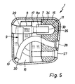
- FIG. 5 shows another embodiment of an inlet pipe 8 shown.
- the remaining parts of the exhaust silencer correspond the embodiment variant according to FIGS. 1 to 4. The same parts are therefore provided with the same reference numerals.
- the inlet pipe 8 according to Figure 5 has no blind end the right side in the second absorption chamber 15 as in first-mentioned embodiment, but an open end End 33.
- the end 33 is coaxial and with Circumferential distance in a deflection tube 11 open on one side.
- the deflection tube 11 is arranged in the second absorption chamber 15 and fastened in an opening of the second partition 7.
- the annular outlet opening of the deflection tube 11 points into the second reflection chamber 17.
- the deflection tube 11 is perforated on the jacket side and therefore has passages 34 for second absorption chamber 15.
- the inlet pipe 8 has a tapered, stepped end section 8a at least in the area of the deflection tube 11.
- the cross section of the stepped end section 8a of the inlet pipe is equal to the cross section of the annular outlet opening of the deflection tube 11.
- the deflection tube 11 has on the outlet side of the exhaust muffler a closed in the second absorption chamber 15 dome-shaped front end 35.
- the exhaust muffler is attached to a vehicle underbody so that the first and the second absorption chamber 14, 15 towards the vehicle underbody point, i.e. in the vicinity of the vehicle underbody lie and thus against thermal insulation the vehicle underbody is set up.
- the hot opposite In contrast, the wall of the silencer is the underground on which the vehicle is moving. In this way, even when driving slowly or when the vehicle is stationary, if there is little or no cooling is given by the wind, the vehicle underbody not be overheated.
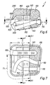
- an exhaust gas silencer 1 comprises in the four-chamber design of a passenger car, an outer housing, which consists of an upper outer half-shell 200 and a lower outer half shell 300, which in their horizontal parting plane by means of an angled circumferential fold 900 are firmly connected.
- peripheral fold 900 there is also an upper inner shell 400 attached, as will be described below.
- the inner exhaust duct extends through the exhaust muffler 1 with the two curved outlet pipes.
- the exhaust muffler 1 further includes a first inner radial Partition 150 and a second inner radial partition 140, being the exit side of the exhaust muffler assigned second partition 140 over the entire inner Cross section of the exhaust silencer 1 extends with the outer housing is firmly connected.
- the already mentioned upper inner shell 400 is on the inlet side of the exhaust muffler interior and extends itself up to the second partition 140 with which it is firmly connected.
- the first partition 150 extends over the entire lower one Half-shell cross-section up to the upper inner shell 400 and is firmly connected to the upper inner shell.
- the one located on the inlet side of the exhaust silencer 1 Space between the upper inner shell 400 and the upper Outer half-shell 200 of the outer housing up to the second partition 140 is filled with a first sound absorbent. It forms a first absorption chamber 160.
- the one located on the outlet side of the exhaust muffler 1 Space between the second partition 140 and the outer case is filled with a second sound absorbent. He forms a second absorption chamber 170.
- the one located on the inlet side of the exhaust silencer 1 Space between the upper inner shell 400 and the lower one Half-shell 300 of the outer housing up to the first partition 150 is an empty space. It forms a first reflection chamber.
- the space between the upper inner shell 400 and the lower one Outer half-shell 300 and between the first and the second Partition 150, 140 is also an empty space. It forms one second reflection chamber.
- edges 500 of the outer half-shells 200 300 formed flat, and it is the flat edge 600 of the inner shell 400 between the flat edges 500 of the outer half-shells only in a partial area T1 of the circumferential fold 900 firmly clamped by the angled circumferential fold 900.
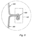
- the two flat edges 500 of the outer half-shells 200, 300 clamped directly against each other and create an additional sealing area in addition to the angled one Circumferential fold 900 according to FIG. 11.
- the angled circumferential fold 900 is formed downwards and has a simply folded top edge of the top Outer half shell 200.
- the angled circumferential fold 900 has an upper counter-bend 700.
- Both outer half-shells 200, 300 including the circumferential fold 900 are double-walled.
- the lower outer half-shell 300 has an inner bottom 130 on which is turned up over a radius 800 on the edge and is sealingly adjacent to the underside of the inner shell 400.
- a aforementioned circumferential fold 900 is used in an exhaust silencer 1 primarily designed as follows.
- the prefabricated outer half-shells 200, 300 are under Intermediate arrangement of the prefabricated inner shell-400 only in Sub-area T1 of the outer half-shells 200, 300 and after one Installation of the remaining individual parts according to Figures 6 to 9 composed with their flat edges 500, 600 positioned and by an attachment arrangement, not shown prefixed. Then the flat edges 500, 600 a circumferential fold tool 120 is attached, which is shown in FIGS and 11 is shown schematically in broken lines.
- the scheduled Circumferential fold tool 120 is used to form the angled Circumferential fold 900 according to Figures 10 and 11 in one single process step along the flat edges 500 or 500, 600 between the inlet opening 100 and the outlet opening 110 of the pre-fixed by the mounting arrangement Exhaust muffler 1 driven and guided, wherein the edges 500 are bent or angled. After training of the angled circumferential fold 900 over the entire circumference of the exhaust muffler 1 on both sides of the exhaust muffler 7 between the inlet opening 100 and the exhaust ports 110 will eventually become the exhaust silencer 1 removed from the released mounting arrangement.
- the aforementioned prefixing of the exhaust silencer 1 can also through positive interlocking raised and lowered Areas of the outer half-shells and the inner shell (s) take place, in particular in the area of the inlet opening 100 and / or the outlet opening 110. Then there is a separate fastening arrangement possibly unnecessary.
Landscapes
- Engineering & Computer Science (AREA)
- Chemical & Material Sciences (AREA)
- Combustion & Propulsion (AREA)
- Mechanical Engineering (AREA)
- General Engineering & Computer Science (AREA)
- Exhaust Silencers (AREA)
Abstract
Description
- Vier-Kammer-Schalen-Schalldämpfer mit zwei nicht-durchströmten Absorptionskammern und zwei durchströmten Reflexionskammern
- Kammeraufteilung durch zwei Quer-Innenböden plus einer im Schalenfalz verankerten Innenschale
- Ein- und Auslaufkammer werden durch die perforierte Innenschale plus zwei perforierten Innenböden mit unterschiedlichem Querschnitt gebildet
- Einlaufrohr mit drei Perforations-Blöcken in den beiden Reflexionskammern bzw. in der zweiten Absorptions-Pufferkammer
- Einlaufrohr wahlweise mit gestuftem Eintrittsquerschnitt plus im zweiten Innenboden verankertem Rückstromrohr
- Verlängerung der inneren Auslaufrohre durch spezielle Biegungen quer zur Längsachse
- Durchmesserverhältnis der inneren Auslaufrohre zu den Endrohren ca. 40 zu 52
- Niedrige Oberflächentemperaturen in Richtung Fahrzeugboden durch die beiden Absorptionskammern
- Figur 1
- einen Abgas-Schalldämpfer in Vierkammer-Bauweise in Halbschalentechnik schematisch in einem Vertikalschnitt,
- Figur 2
- den Abgas-Schalldämpfer nach Figur 1 in einem Horizontalschnitt längs der Linie X-X,
- Figur 3
- den Abgas-Schalldämpfer nach Figur 1 in einem Querschnitt längs der Linie A-A,
- Figur 4
- den Abgas-Schalldämpfer nach Figur 1 in einem Querschnitt längs der Linie B-B,
- Figur 5
- einen anderen Abgas-Schalldämpfer in einem Horizontalschnitt ähnlich Figur 2,
- Figur 6
- einen Abgas-Schalldämpfer in Vierkammer-Bauweise in Halbschalentechnik schematisch in einem Vertikalschnitt,
- Figur 7
- den Abgas-Schalldämpfer nach Figur 6 in einem Horizontalschnitt längs der Linie X-X,
- Figur 8
- den Abgas-Schalldämpfer nach Figur 7 in einem Querschnitt längs der Linie A1-A1,
- Figur 9
- den Abgas-Schalldämpfer nach Figur 7 in einem Querschnitt längs der Linie B1-B1,
- Figur 10
- die Einzelheit C1 der Figur 8 eines Umfangsfalzes im Teilbereich einer Zwischenanordnung einer Innenschale in größerer Darstellung, und
- Figur 11
- die Einzelheit D1 der Figur 9 des gleichen Umfangsfalzes ohne Zwischenanordnung einer Innenschale in größerer Darstellung.
Claims (32)
- Abgas-Schalldämpfer (1) in Mehrkammerbauweise, insbesondere Abgas-Schalldämpfer eines Personenkraftfahrzeuges, mit einem Außengehäuse (2) bestehend aus einer oberen und einer unteren Halbschale (3, 4), einer Innenschale (5) sowie einer inneren Abgasführung durch den Abgas-Schalldämpfer,
dadurch gekennzeichnet, daß die Abgasführung zumindest ein erstes gekrümmtes Auslaufrohr (9) besitzt, das einen ersten Krümmungsabschnitt aufweist und dessen vorzugsweise geradliniges Austrittsende (27) bündig mit dem Außengehäuse (2) verläuft. - Abgas-Schalldämpfer nach Anspruch 1,
dadurch gekennzeichnet, daß ein zweites gekrümmtes Auslaufrohr (10) mit einem zweiten Krümmungsabschnitt und einem zweiten vorzugsweise geradlinigen Austrittsende (28) vorgesehen ist, wobei die Krümmungabschnitte des ersten Auslaufrohrs (9) und des zweiten Auslaufrohrs (10) in Draufsicht aufeinander zugerichtet sind. - Abgas-Schalldämpfer nach Anspruch 2,
dadurch gekennzeichnet, daß die Krümmungsabschnitte des ersten Auslaufrohres (9) und des zweiten Auslaufrohres (10) sich in unterschiedlicher Höhe im Abgas-Schalldämpfer überkreuzen. - Abgas-Schalldämpfer nach Anspruch 3,
dadurch gekennzeichnet, daß die Austrittsenden (27, 28) des ersten Auslaufrohres (9) und des zweiten Auslaufrohres (10) auf der Austrittsseite des Abgas-Schalldämpfers parallel und in einem dichten Abstand (a) zueinander in einer Horizontalebene angeordnet sind, und die Eintrittsenden (29, 30) des ersten Auslaufrohres (9) und des zweiten Auslaufrohres (10) auf der entgegengesetzten Eintrittsseite des Abgas-Schalldämpfers sich in den seitlichen inneren Eckbereichen des Abgas-Schalldämpfers in einer ersten Reflexionskammer (16) befinden. - Abgas-Schalldämpfer nach einem der Ansprüche 1 bis 4,
dadurch gekennzeichnet, daß die Auslaufrohre (9, 10) einen unperforierten Mantel besitzen. - Abgas-Schalldämpfer nach einem der Ansprüche 1 bis 5,
dadurch gekennzeichnet, daß die Auslaufrohre (9, 10) ein gestuftes erweiteres Ende (31) besitzen. - Abgas-Schalldämpfer nach Anspruch 6, dadurch gekennzeichnet, daß das Verhältnis des Durchmessers (d) der Auslaufrohre (9, 10) zum Durchmesser (D) des gestuften erweiterten Endes (31) der Auslaufrohre im Bereich von 40 zu 52 liegt.
- Abgas-Schalldämpfer nach einem der Ansprüche 1 bis 7,
dadurch gekennzeichnet, daß eine erste und eine zweite innere radiale Trennwand (6, 7) vorgesehen sind, wobei sich die der Austrittsseite des Abgas-Schalldämpfers zugeordnete zweite Trennwand (7) über den gesamten inneren Querschnitt des Abgas-Schalldämpfers (1) erstreckt und mit dem Außengehäuse (2) fest verbunden ist. - Abgas-Schalldämpfer nach Anspruch 8,
dadurch gekennzeichnet, daß auf der Eintrittsseite des Abgas-Schalldämpfers eine obere Innenschale (5) vorgesehen ist, die sich bis zur zweiten Trennwand (7) erstreckt und mit der zweiten Trennwand fest verbunden ist, und vorzugsweise in einem Schalenfalz (25) der oberen und unteren Halbschale (3, 4) des Außengehäuses verankert ist. - Abgas-Schalldämpfer nach Anspruch 9,
dadurch gekennzeichnet, daß die erste Trennwand (6) sich über den gesamten unteren Halbschalenquerschnitt bis hin zur oberen Innenschale (5) erstreckt und mit der oberen Innenschale fest verbunden ist. - Abgas-Schalldämpfer nach Anspruch 10,
dadurch gekennzeichnet, daß der auf der Eintrittsseite des Abgas-Schalldämpfers gelegene Raum zwischen der oberen Innenschale (5) und der oberen Halbschale (3) des Außengehäuses (2) bis zur zweiten Trennwand (7) mit Schallschluckstoff ausgefüllt ist und eine erste Absorptionskammer (14) ausbildet. - Abgas-Schalldämpfer nach Anspruch 10 oder 11,
dadurch gekennzeichnet, daß der auf der Austrittsseite des Abgas-Schalldämpfers gelegene Raum zwischen der zweiten Trennwand (7) und dem Außengehäuse (2) mit einem zweiten Schallschluckstoff ausgefüllt ist und eine zweite Absorptionskammer (15) ausbildet. - Abgas-Schalldämpfer nach einem der Ansprüche 10 bis 12,
dadurch gekennzeichnet, daß der auf der Eintrittsseite des Abgas-Schalldämpfers gelegene Raum zwischen der oberen Innenschale (5) und der unteren Halbschale (4) des Außengehäuses (2) bis zur ersten Trennwand (6) ein Leerraum ist und die erste Reflexionskammer (16) ausbildet. - Abgas-Schalldämpfer nach einem der Ansprüche 10 bis 13,
dadurch gekennzeichnet, daß der Raum zwischen der oberen Innenschale (5) und der unteren Halbschale (4) des Außengehäuses sowie zwischen der ersten und der zweiten Trennwand (6, 7) ein Leerraum ist und eine zweite Reflexionskammer (17) ausbildet. - Abgas-Schalldämpfer nach einem der Ansprüche 12 bis 14,
dadurch gekennzeichnet, daß die Abgasführung ein vorzugsweise geradliniges Einlaufrohr (8) aufweist, dessen auf der Austrittsseite des Abgas-Schalldämpfers gelegenes Ende sich in der zweiten Absorptionskammer (15) befindet. - Abgas-Schalldämpfer nach Anspruch 15,
dadurch gekennzeichnet, daß das Einlaufrohr (8) zumindest teilweise mantelseitig perforiert ist und dadurch Durchgänge (22, 23) zumindest zur ersten Reflexionskammer (16) und zur zweiten Reflexionskammer (17) besitzt. - Abgas-Schalldämpfer nach Anspruch 15 oder 16,
dadurch gekennzeichnet, daß die erste und die zweite Trennwand (6, 7) Durchgangsöffnungen für das Einlaufrohr (8) und die Auslaufrohre (9, 10) aufweisen, wobei das Einlaufrohr und die Auslaufrohre zumindest mit der ersten Trennwand (6) fest verbunden sind. - Abgas-Schalldämpfer nach einem der Ansprüche 9 bis 17,
dadurch gekennzeichnet, daß die erste und die zweite Trennwand (6, 7) sowie die obere Innenschale (5) zumindest teilweise Perforationen (18, 19, 20, 21) aufweisen. - Abgas-Schalldämpfer nach einem der Ansprüche 15 bis 18,
dadurch gekennzeichnet, daß das Einlaufrohr (8) einen abwinkeltes Einlauf aufweist, der mit dem Außengehäuse (2) bündig verläuft. - Abgas-Schalldämpfer nach einem der Ansprüche 15 bis 19,
dadurch gekennzeichnet, daß das Einlaufrohr (8) in der zweiten Absorptionskammer (15) ein geschlossenes stirnseites Ende (32) sowie eine Mantelperforation (24) im Bereich der zweiten Absorptionskammer (15) besitzt. - Abgas-Schalldämpfer nach einem der Ansprüche 15 bis 19,
dadurch gekennzeichnet, daß das Einlaufrohr (8) in der zweiten Absorptionkammer (15) ein offenes stirnseitiges Ende (33) besitzt, welches koaxial und mit Umfangsabstand in einem einseitig offenen Umlenkrohr (11) angeordnet ist, das seinerseits in der zweiten Absorptionskammer (15) angeordnet und in einem Durchbruch der zweiten Trennwand (7) befestigt ist, und die ringförmige Austrittsöffnung des Umlenkrohres (11) in die zweite Reflexionskammer (17) weist. - Abgas-Schalldämpfer nach Anspruch 21,
dadurch gekennzeichnet, daß das Umlenkrohr (11) mantelseitig perforiert ist und dadurch Durchgänge (34) zur zweiten Absorptionskammer (15) besitzt. - Abgas-Schalldämpfer nach Anspruch 21 oder 22,
dadurch gekennzeichnet, daß das Einlaufrohr (8) einen verjüngten, abgestuften Endabschnitt (8a) zumindest im Bereich des Umlenkrohres (11) besitzt. - Abgas-Schalldämpfer nach Anspruch 23,
dadurch gekennzeichnet, daß der Querschnitt des abgestuften Endabschnitts (8a) des Einlaufrohres gleich dem Querschnitt der ringförmigen Austrittsöffnung des Umlenkrohres (11) ist. - Abgas-Schalldämpfer nach einem der Ansprüche 21 bis 24,
dadurch gekennzeichnet, daß das Umlenkrohr (11) auf der Austrittsseite des Abgas-Schalldämpfers in der zweiten Absorptionskammer (15) ein geschlossenes kalottenförmiges stirnseitiges Umlenkende (35) besitzt. - Abgas-Schalldämpfer nach einem der Ansprüche 12 bis 25,
dadurch gekennzeichnet, daß dieser an einem Fahrzeug-Unterboden dergestalt befestigbar ist, daß die erste und die zweite Absorptionskammer (14, 15) in Richtung Fahrzeug-Unterboden weisen. - Abgas-Schalldämpfer nach einem der Ansprüche 9 bis 26, mit einem Schalenfalz in Form eines abgewinkelten Umfangsfalzes (900) und mit zwei Außenhalbschalen (200, 300) jeweils mit einem Rand (500) sowie zumindest einer Innenschale (400) mit einem flachen Rand (600), wobei die Ränder (500) der Außenhalbschalen (200, 300) außenseitig abgewinkelt und über den Umfangsfalz (900) miteinander verbunden sind und der flache Rand (600) der Innenschale(n) (400) zwischen den Rändern (500) der Außenhalbschalen fest eingeklemmt ist,
dadurch gekennzeichnet, daß die Ränder (500) der Außenhalbschalen (200, 300) flach ausgebildet sind, und daß der flache Rand (600) der Innenschale(n) (400) zwischen den flachen Rändern (500) der Außenhalbschalen nur in einem Teilbereich (T1) des Umfangsfalzes (900) durch den abgewinkelten Umfangsfalz (900) fest eingeklemmt ist. - Schalldämpfer nach Anspruch 27,
dadurch gekennzeichnet, daß der abgewinkelte Umfangsfalz (900) nach unten ausgebildet ist und einen einfach umgeschlagenen oberen Rand einer oberen Außenhalbschale (200) aufweist. - Schalldämpfer nach Anspruch 28,
dadurch gekennzeichnet, daß der abgewinkelte Umfangsfalz (900) eine obere Gegenbiegung (700) oder obere Gegenabwinklung aufweist. - Schalldämpfer nach einem der Ansprüche 27 bis 29,
dadurch gekennzeichnet, daß zumindest die Außenhalbschalen (200, 300) und der abgewinkelte Umfangsfalz (900) doppelwandig ausgebildet sind. - Schalldämpfer nach einem der Ansprüche 27 bis 30,
dadurch gekennzeichnet, daß eine untere Außenhalbschale (300) einen Innenboden (130) aufweist, welcher über einen Radius (800) randseitig hochgeschlagen ist und an der Unterseite der Innenschale (400) abdichtend angrenzt. - Verfahren zur Herstellung eines Abgas-Schalldämpfers (1) mit einem abgewinkelten Umfangsfalz (900),
dadurch gekennzeichnet, daß vorgefertigte Außenhalbschalen (200, 300) unter Zwischenordnung zumindest einer vorgefertigten Innenschale (400) nur in einem Teilbereich (T1) der Außenhalbschalen (200, 300) und nach einem Einbau gegebenenfalls weiterer Einzelteile mit ihren flachen Rändern (500, 600) positioniert zusammengesetzt und vorfixiert werden, und daß der abgewinkelte Umfangsfalz (900) in einem einzigen Verfahrensschritt mit einem vorzugsweise einzigen Umfangsfalz-Werkzeug (120) ausgebildet wird, wobei das Umfangsfalz-Werkzeug (120) auf den flachen Rändern (500 bzw. 500, 600) zwischen Eintritts- und Austrittsöffnung (100, 110) des vorfixierten Abgas-Schalldämpfers (1) geführt und angetrieben wird.
Priority Applications (1)
| Application Number | Priority Date | Filing Date | Title |
|---|---|---|---|
| EP06011041A EP1693556A3 (de) | 2000-04-14 | 2001-02-16 | Abgas-Schalldämpfer mit einem Schalenfalz und Verfahren zur Herstellung eines Abgas-Schalldämpfers |
Applications Claiming Priority (4)
| Application Number | Priority Date | Filing Date | Title |
|---|---|---|---|
| DE10018505 | 2000-04-14 | ||
| DE10018505 | 2000-04-14 | ||
| DE10058142A DE10058142A1 (de) | 2000-04-14 | 2000-11-22 | Abgas-Schalldämpfer in Mehrkammerbauweise |
| DE10058142 | 2000-11-22 |
Related Child Applications (1)
| Application Number | Title | Priority Date | Filing Date |
|---|---|---|---|
| EP06011041A Division EP1693556A3 (de) | 2000-04-14 | 2001-02-16 | Abgas-Schalldämpfer mit einem Schalenfalz und Verfahren zur Herstellung eines Abgas-Schalldämpfers |
Publications (3)
| Publication Number | Publication Date |
|---|---|
| EP1146206A2 true EP1146206A2 (de) | 2001-10-17 |
| EP1146206A3 EP1146206A3 (de) | 2002-10-02 |
| EP1146206B1 EP1146206B1 (de) | 2006-08-02 |
Family
ID=26005310
Family Applications (1)
| Application Number | Title | Priority Date | Filing Date |
|---|---|---|---|
| EP01103818A Expired - Lifetime EP1146206B1 (de) | 2000-04-14 | 2001-02-16 | Abgas-Schalldämpfer in Mehrkammerbauweise |
Country Status (4)
| Country | Link |
|---|---|
| US (1) | US7004283B2 (de) |
| EP (1) | EP1146206B1 (de) |
| DE (1) | DE50110583D1 (de) |
| WO (1) | WO2001079665A2 (de) |
Cited By (4)
| Publication number | Priority date | Publication date | Assignee | Title |
|---|---|---|---|---|
| EP1347155A3 (de) * | 2002-03-19 | 2003-11-12 | Dr.Ing. h.c.F. Porsche Aktiengesellschaft | Nachschalldämpfer |
| EP1512852A3 (de) * | 2003-09-05 | 2005-08-10 | Faurecia Exhaust Systems, Inc. | Schalldämpfer mit innenliegender Wärmeabschirmung |
| EP1541823A3 (de) * | 2003-12-09 | 2006-03-15 | J. Eberspächer GmbH & Co. KG | Schalldämpfer für eine Abgasanlage |
| CN101881203A (zh) * | 2010-06-29 | 2010-11-10 | 江苏天宇石化冶金设备有限公司 | 管道消音器 |
Families Citing this family (26)
| Publication number | Priority date | Publication date | Assignee | Title |
|---|---|---|---|---|
| FR2838476B1 (fr) * | 2002-04-12 | 2005-06-24 | Faurecia Sys Echappement | Volume d'echappement comportant une enveloppe delimitant un passage de circulation des gaz |
| DE10346479A1 (de) * | 2003-10-02 | 2005-05-12 | Bayerische Motoren Werke Ag | Abgasanlage für eine Brennkraftmaschine |
| US20060081416A1 (en) * | 2004-10-14 | 2006-04-20 | Nentrup Trent L | Exhaust silencer with acoustic damping mat |
| JP2006151298A (ja) * | 2004-11-30 | 2006-06-15 | Honda Motor Co Ltd | 燃料電池自動車 |
| JP2006250055A (ja) * | 2005-03-11 | 2006-09-21 | Toyota Motor Corp | 内燃機関の消音器 |
| DE102006008941A1 (de) * | 2006-02-23 | 2007-08-30 | J. Eberspächer GmbH & Co. KG | Schalldämpfer für eine Abgasanlage |
| DE102006049786B4 (de) * | 2006-10-21 | 2013-12-24 | Dr. Ing. H.C. F. Porsche Aktiengesellschaft | 1 bis Abgasnachschalldämpfer |
| DE102007027371A1 (de) * | 2007-06-11 | 2008-12-18 | Cognis Oleochemicals Gmbh | Verfahren zur Herstellung einer Verbindung aufweisend mindestens eine Ester-Gruppe |
| DE102007027372A1 (de) * | 2007-06-11 | 2008-12-18 | Cognis Oleochemicals Gmbh | Verfahren zur Hydrierung von Glycerin |
| US20090000863A1 (en) * | 2007-06-28 | 2009-01-01 | Share Win Industry Co., Ltd. | Exhaust pipe |
| DE102009014435A1 (de) * | 2009-03-26 | 2010-10-14 | J. Eberspächer GmbH & Co. KG | Abgasbehandlungseinrichtung |
| CN103764966B (zh) * | 2011-09-05 | 2016-05-11 | 本田技研工业株式会社 | 排气消声装置 |
| DE102012006544B4 (de) * | 2012-04-02 | 2015-12-31 | Tenneco Gmbh | Schalldämpfer mit Ankopplung Endrohr über Kopplungskammer |
| KR101316133B1 (ko) * | 2012-08-10 | 2013-10-08 | 현대자동차주식회사 | 차량용 소음기 |
| US8739923B1 (en) * | 2013-01-03 | 2014-06-03 | Faurecia Emmissions Control Technologies | Muffler for vehicle exhaust system |
| JP6153371B2 (ja) * | 2013-04-15 | 2017-06-28 | ニチアス株式会社 | マフラーカッター |
| US9261009B2 (en) * | 2013-07-03 | 2016-02-16 | Honda Motor Co., Ltd. | Automotive muffler |
| US20170067379A1 (en) * | 2014-02-25 | 2017-03-09 | Bombardier Recreational Products Inc. | Muffler for an exhaust system of an internal combustion engine |
| DE102014217058A1 (de) * | 2014-08-27 | 2016-03-03 | Eberspächer Exhaust Technology GmbH & Co. KG | Schalldämpfer |
| US11690815B2 (en) * | 2015-08-05 | 2023-07-04 | Cmpd Licensing Llc | Hyperkeratotic skin condition treatments and compositions |
| KR102532322B1 (ko) | 2018-03-29 | 2023-05-15 | 현대자동차주식회사 | 차량용 소음기 |
| EP3557015B1 (de) * | 2018-04-20 | 2020-11-04 | Volvo Car Corporation | Schalldämpfer mit einem helmholtz resonator and fahrzeug mit einem solchen schalldämpfer |
| KR20210051829A (ko) * | 2019-10-31 | 2021-05-10 | 현대자동차주식회사 | 스포티 배기 음색 구현을 위한 자동차용 소음기 |
| DE102019132097A1 (de) * | 2019-11-27 | 2021-05-27 | Eberspächer Exhaust Technology GmbH | Abgasschalldämpfer |
| KR102869234B1 (ko) * | 2020-05-13 | 2025-10-10 | 현대자동차주식회사 | 차량의 배기계 소음 저감 장치 |
| DE102021113611A1 (de) * | 2021-05-26 | 2022-12-01 | Umfotec Gmbh | Schallminderer, Verfahren zu dessen Herstellung und Fluidleitungssystem mit einem solchen Schallminderer |
Citations (2)
| Publication number | Priority date | Publication date | Assignee | Title |
|---|---|---|---|---|
| EP0664380A1 (de) | 1994-01-20 | 1995-07-26 | HEINRICH GILLET GMBH & CO. KG | Schalldämpfer |
| DE19627079A1 (de) | 1996-07-05 | 1998-01-08 | Eberspaecher J Gmbh & Co | Absorptions-/Reflexions-Schalldämpfer |
Family Cites Families (25)
| Publication number | Priority date | Publication date | Assignee | Title |
|---|---|---|---|---|
| US3776366A (en) * | 1972-07-24 | 1973-12-04 | Outboard Marine Corp | Exhaust muffler |
| GB1448301A (en) * | 1973-01-16 | 1976-09-02 | Gillet Gmbh Paul | Exhaust silencers |
| US4111279A (en) * | 1976-07-26 | 1978-09-05 | Tenneco Inc. | Louver flow muffler |
| US4132286A (en) * | 1976-08-31 | 1979-01-02 | Nihon Radiator Co., Ltd. | Muffler |
| US4235304A (en) * | 1976-08-31 | 1980-11-25 | Nihon Radiator Co., Ltd. | Muffler |
| US4119174A (en) * | 1977-05-20 | 1978-10-10 | Skyway Recreation Products | Engine muffler |
| JPS6053164B2 (ja) * | 1978-09-21 | 1985-11-25 | 富士重工業株式会社 | 自動車用マフラ |
| USRE31724E (en) * | 1979-01-18 | 1984-11-06 | Yamaha Hatsudoki Kabushiki Kaisha | Motorcycle exhaust systems |
| US4574913A (en) * | 1983-11-11 | 1986-03-11 | Sankei Giken Kogyo Kabushiki Kaisha | Muffler with spark arresting function |
| DE8709527U1 (de) * | 1987-07-10 | 1987-10-15 | Paul Gillet Gmbh, 6732 Edenkoben | Abgasschalldämpfer |
| DE3837677A1 (de) * | 1987-11-17 | 1989-06-01 | Volkswagen Ag | Bei hohen betriebstemperaturen arbeitender schalldaempfer, insbesondere fuer eine kraftfahrzeug-brennkraftmaschine |
| JPH06575Y2 (ja) * | 1988-06-16 | 1994-01-05 | 川崎重工業株式会社 | 内燃機関用マフラー |
| JP2559477B2 (ja) * | 1988-10-05 | 1996-12-04 | 日産自動車株式会社 | 排気消音装置 |
| JPH0712650Y2 (ja) * | 1989-02-23 | 1995-03-29 | マツダ株式会社 | エンジンの排気サイレンサ |
| US4941545A (en) * | 1989-04-28 | 1990-07-17 | Arvin Industries, Inc. | Muffler assembly |
| DE9100866U1 (de) * | 1991-01-25 | 1992-05-27 | Roth-Technik GmbH, 7560 Gaggenau | Schalldämpfer für eine Abgasanlage |
| FR2682158B1 (fr) * | 1991-10-04 | 1993-12-10 | Wimetal Sa | Silencieux de ligne d'echappement pour vehicule automobile. |
| DE4140429C2 (de) * | 1991-12-07 | 2000-05-25 | Eberspaecher J Gmbh & Co | Schalldämpfer für Verbrennungsmotoren |
| DE9307567U1 (de) * | 1993-05-18 | 1994-09-29 | Roth-Technik GmbH, 76571 Gaggenau | Abgasschalldämpfer |
| DE9308419U1 (de) * | 1993-06-05 | 1994-10-13 | Roth-Technik GmbH, 76571 Gaggenau | Schalldämpfer für vorzugsweise gasförmige Medien |
| DE19627299A1 (de) * | 1996-07-06 | 1998-01-08 | Eberspaecher J Gmbh & Co | Schalldämpfer mit Außen- und Innenhalbschalen |
| SE520282C2 (sv) * | 1998-12-30 | 2003-06-17 | Volvo Personvagnar Ab | Slutrör vid ljuddämpare med perforeringar för dämpning av lågfrekent och högfrekent buller |
| JP3789742B2 (ja) * | 2000-09-08 | 2006-06-28 | 本田技研工業株式会社 | 排気消音器 |
| JP3943818B2 (ja) * | 2000-09-21 | 2007-07-11 | 本田技研工業株式会社 | エンジンの消音器 |
| DE10060522B4 (de) * | 2000-12-06 | 2004-07-22 | J. Eberspächer GmbH & Co. KG | Abgas-Schalldämpfer für ein brennstoffbetriebenes Heizgerät |
-
2001
- 2001-02-16 EP EP01103818A patent/EP1146206B1/de not_active Expired - Lifetime
- 2001-02-16 DE DE50110583T patent/DE50110583D1/de not_active Expired - Fee Related
- 2001-04-12 US US10/257,818 patent/US7004283B2/en not_active Expired - Fee Related
- 2001-04-12 WO PCT/EP2001/004234 patent/WO2001079665A2/de not_active Ceased
Patent Citations (2)
| Publication number | Priority date | Publication date | Assignee | Title |
|---|---|---|---|---|
| EP0664380A1 (de) | 1994-01-20 | 1995-07-26 | HEINRICH GILLET GMBH & CO. KG | Schalldämpfer |
| DE19627079A1 (de) | 1996-07-05 | 1998-01-08 | Eberspaecher J Gmbh & Co | Absorptions-/Reflexions-Schalldämpfer |
Cited By (5)
| Publication number | Priority date | Publication date | Assignee | Title |
|---|---|---|---|---|
| EP1347155A3 (de) * | 2002-03-19 | 2003-11-12 | Dr.Ing. h.c.F. Porsche Aktiengesellschaft | Nachschalldämpfer |
| EP1512852A3 (de) * | 2003-09-05 | 2005-08-10 | Faurecia Exhaust Systems, Inc. | Schalldämpfer mit innenliegender Wärmeabschirmung |
| CN1603590B (zh) * | 2003-09-05 | 2012-05-09 | 法雷西亚排气系统公司 | 带有内部热屏蔽的消声器 |
| EP1541823A3 (de) * | 2003-12-09 | 2006-03-15 | J. Eberspächer GmbH & Co. KG | Schalldämpfer für eine Abgasanlage |
| CN101881203A (zh) * | 2010-06-29 | 2010-11-10 | 江苏天宇石化冶金设备有限公司 | 管道消音器 |
Also Published As
| Publication number | Publication date |
|---|---|
| US7004283B2 (en) | 2006-02-28 |
| US20040003963A1 (en) | 2004-01-08 |
| EP1146206B1 (de) | 2006-08-02 |
| WO2001079665A2 (de) | 2001-10-25 |
| WO2001079665A3 (de) | 2002-12-05 |
| DE50110583D1 (de) | 2006-09-14 |
| EP1146206A3 (de) | 2002-10-02 |
Similar Documents
| Publication | Publication Date | Title |
|---|---|---|
| EP1146206B1 (de) | Abgas-Schalldämpfer in Mehrkammerbauweise | |
| EP1914398B1 (de) | Abgasnachschalldämpfer | |
| DE3783872T2 (de) | Durch stanzverfahren hergestellter schalldaempfer. | |
| DE2738600A1 (de) | Schalldaempfer | |
| DE60308618T2 (de) | Fingerförmiges Klappenventil | |
| DE4121525A1 (de) | Schalldaempfer mit einstueckigem gehaeuse | |
| WO2019121744A1 (de) | Breitbanddämpfer für einen kraftfahrzeug-motor | |
| DE69815636T2 (de) | Abgasschalldämpfer für einen universellen Kleinmotor | |
| DE10060522B4 (de) | Abgas-Schalldämpfer für ein brennstoffbetriebenes Heizgerät | |
| DE19846666C2 (de) | Schalldämpfende Leitung | |
| DE10104835C1 (de) | Abgaskühler | |
| DE112006003265T5 (de) | Auspufftopfeinheit mit schalldämpfendem Element | |
| EP1321639B2 (de) | Schalldämpfungseinrichtung | |
| DE29802099U1 (de) | Abgasschalldämpfer für einen Zweitaktmotor | |
| EP0816648A1 (de) | Schalldämpfer für Kraftfahrzeuge | |
| DE10243881A1 (de) | Schalldämpfer zur Verringerung von Luftgeräuschen und Verfahren zur Herstellung desselben | |
| DE2808166C3 (de) | ||
| DE602005005461T2 (de) | Schalldämpfer für abgassysteme von fahrzeugen | |
| EP1693556A2 (de) | Abgas-Schalldämpfer mit einem Schalenfalz und Verfahren zur Herstellung eines Abgas-Schalldämpfers | |
| DE2738601C2 (de) | Schalldämpfer | |
| DE1426198A1 (de) | Schalldaempfer | |
| DE19849118A1 (de) | Abgasschalldämpfer | |
| DE19636662B4 (de) | Abgaskatalysator für Verbrennungsmotoren | |
| DE2930775A1 (de) | Schalldaempfer fuer abgase. | |
| DE19902951A1 (de) | Ansaugvorrichtung mit einem Leitungsabschnitt zur Dämpfung des Ansauggeräusches |
Legal Events
| Date | Code | Title | Description |
|---|---|---|---|
| PUAI | Public reference made under article 153(3) epc to a published international application that has entered the european phase |
Free format text: ORIGINAL CODE: 0009012 |
|
| AK | Designated contracting states |
Kind code of ref document: A2 Designated state(s): AT BE CH CY DE DK ES FI FR GB GR IE IT LI LU MC NL PT SE TR |
|
| AX | Request for extension of the european patent |
Free format text: AL;LT;LV;MK;RO;SI |
|
| RAP1 | Party data changed (applicant data changed or rights of an application transferred) |
Owner name: J. EBERSPAECHER GMBH & CO. KG |
|
| PUAL | Search report despatched |
Free format text: ORIGINAL CODE: 0009013 |
|
| AK | Designated contracting states |
Kind code of ref document: A3 Designated state(s): AT BE CH CY DE DK ES FI FR GB GR IE IT LI LU MC NL PT SE TR |
|
| AX | Request for extension of the european patent |
Free format text: AL;LT;LV;MK;RO;SI |
|
| 17P | Request for examination filed |
Effective date: 20020822 |
|
| AKX | Designation fees paid |
Designated state(s): DE FR GB IT |
|
| 17Q | First examination report despatched |
Effective date: 20050614 |
|
| GRAP | Despatch of communication of intention to grant a patent |
Free format text: ORIGINAL CODE: EPIDOSNIGR1 |
|
| GRAS | Grant fee paid |
Free format text: ORIGINAL CODE: EPIDOSNIGR3 |
|
| GRAA | (expected) grant |
Free format text: ORIGINAL CODE: 0009210 |
|
| AK | Designated contracting states |
Kind code of ref document: B1 Designated state(s): DE FR GB IT |
|
| PG25 | Lapsed in a contracting state [announced via postgrant information from national office to epo] |
Ref country code: IT Free format text: LAPSE BECAUSE OF FAILURE TO SUBMIT A TRANSLATION OF THE DESCRIPTION OR TO PAY THE FEE WITHIN THE PRESCRIBED TIME-LIMIT;WARNING: LAPSES OF ITALIAN PATENTS WITH EFFECTIVE DATE BEFORE 2007 MAY HAVE OCCURRED AT ANY TIME BEFORE 2007. THE CORRECT EFFECTIVE DATE MAY BE DIFFERENT FROM THE ONE RECORDED. Effective date: 20060802 |
|
| REG | Reference to a national code |
Ref country code: GB Ref legal event code: FG4D Free format text: NOT ENGLISH |
|
| RIN1 | Information on inventor provided before grant (corrected) |
Inventor name: NEU, HELMUT Inventor name: SCHUMACHER, HERBERT Inventor name: KLEIN, NORBERT Inventor name: GIEBEL, STEPHAN Inventor name: WOERNER, SIEGFRIED |
|
| REF | Corresponds to: |
Ref document number: 50110583 Country of ref document: DE Date of ref document: 20060914 Kind code of ref document: P |
|
| GBT | Gb: translation of ep patent filed (gb section 77(6)(a)/1977) |
Effective date: 20061023 |
|
| ET | Fr: translation filed | ||
| PLBE | No opposition filed within time limit |
Free format text: ORIGINAL CODE: 0009261 |
|
| STAA | Information on the status of an ep patent application or granted ep patent |
Free format text: STATUS: NO OPPOSITION FILED WITHIN TIME LIMIT |
|
| 26N | No opposition filed |
Effective date: 20070503 |
|
| PGFP | Annual fee paid to national office [announced via postgrant information from national office to epo] |
Ref country code: DE Payment date: 20090228 Year of fee payment: 9 |
|
| PGFP | Annual fee paid to national office [announced via postgrant information from national office to epo] |
Ref country code: GB Payment date: 20090223 Year of fee payment: 9 |
|
| PGFP | Annual fee paid to national office [announced via postgrant information from national office to epo] |
Ref country code: IT Payment date: 20090226 Year of fee payment: 9 |
|
| PGFP | Annual fee paid to national office [announced via postgrant information from national office to epo] |
Ref country code: FR Payment date: 20090217 Year of fee payment: 9 |
|
| GBPC | Gb: european patent ceased through non-payment of renewal fee |
Effective date: 20100216 |
|
| REG | Reference to a national code |
Ref country code: FR Ref legal event code: ST Effective date: 20101029 |
|
| PG25 | Lapsed in a contracting state [announced via postgrant information from national office to epo] |
Ref country code: FR Free format text: LAPSE BECAUSE OF NON-PAYMENT OF DUE FEES Effective date: 20100301 |
|
| PG25 | Lapsed in a contracting state [announced via postgrant information from national office to epo] |
Ref country code: DE Free format text: LAPSE BECAUSE OF NON-PAYMENT OF DUE FEES Effective date: 20100901 |
|
| PG25 | Lapsed in a contracting state [announced via postgrant information from national office to epo] |
Ref country code: IT Free format text: LAPSE BECAUSE OF NON-PAYMENT OF DUE FEES Effective date: 20100216 Ref country code: GB Free format text: LAPSE BECAUSE OF NON-PAYMENT OF DUE FEES Effective date: 20100216 |