EP1144781B1 - Systeme de securite pour un ouvrant de vehicule automobile - Google Patents
Systeme de securite pour un ouvrant de vehicule automobile Download PDFInfo
- Publication number
- EP1144781B1 EP1144781B1 EP00967986A EP00967986A EP1144781B1 EP 1144781 B1 EP1144781 B1 EP 1144781B1 EP 00967986 A EP00967986 A EP 00967986A EP 00967986 A EP00967986 A EP 00967986A EP 1144781 B1 EP1144781 B1 EP 1144781B1
- Authority
- EP
- European Patent Office
- Prior art keywords
- ring
- face
- oriented towards
- security system
- window
- Prior art date
- Legal status (The legal status is an assumption and is not a legal conclusion. Google has not performed a legal analysis and makes no representation as to the accuracy of the status listed.)
- Expired - Lifetime
Links
- 230000002093 peripheral effect Effects 0.000 claims description 14
- 239000000463 material Substances 0.000 claims description 5
- 229920001971 elastomer Polymers 0.000 claims 1
- 239000000806 elastomer Substances 0.000 claims 1
- 238000001514 detection method Methods 0.000 description 2
- 238000010586 diagram Methods 0.000 description 2
- 241001080024 Telles Species 0.000 description 1
- 230000006835 compression Effects 0.000 description 1
- 238000007906 compression Methods 0.000 description 1
- 238000002788 crimping Methods 0.000 description 1
- 239000000428 dust Substances 0.000 description 1
- 238000007373 indentation Methods 0.000 description 1
- 229920003052 natural elastomer Polymers 0.000 description 1
- 229920001194 natural rubber Polymers 0.000 description 1
- 230000000717 retained effect Effects 0.000 description 1
- 238000007789 sealing Methods 0.000 description 1
- 229920003051 synthetic elastomer Polymers 0.000 description 1
- 229920002994 synthetic fiber Polymers 0.000 description 1
Images


Classifications
-
- E—FIXED CONSTRUCTIONS
- E05—LOCKS; KEYS; WINDOW OR DOOR FITTINGS; SAFES
- E05B—LOCKS; ACCESSORIES THEREFOR; HANDCUFFS
- E05B79/00—Mounting or connecting vehicle locks or parts thereof
- E05B79/02—Mounting of vehicle locks or parts thereof
- E05B79/06—Mounting of handles, e.g. to the wing or to the lock
-
- E—FIXED CONSTRUCTIONS
- E05—LOCKS; KEYS; WINDOW OR DOOR FITTINGS; SAFES
- E05B—LOCKS; ACCESSORIES THEREFOR; HANDCUFFS
- E05B81/00—Power-actuated vehicle locks
- E05B81/54—Electrical circuits
- E05B81/64—Monitoring or sensing, e.g. by using switches or sensors
- E05B81/76—Detection of handle operation; Detection of a user approaching a handle; Electrical switching actions performed by door handles
- E05B81/77—Detection of handle operation; Detection of a user approaching a handle; Electrical switching actions performed by door handles comprising sensors detecting the presence of the hand of a user
-
- E—FIXED CONSTRUCTIONS
- E05—LOCKS; KEYS; WINDOW OR DOOR FITTINGS; SAFES
- E05B—LOCKS; ACCESSORIES THEREFOR; HANDCUFFS
- E05B85/00—Details of vehicle locks not provided for in groups E05B77/00 - E05B83/00
- E05B85/01—Mechanical arrangements specially adapted for hands-free locking or unlocking
-
- E—FIXED CONSTRUCTIONS
- E05—LOCKS; KEYS; WINDOW OR DOOR FITTINGS; SAFES
- E05B—LOCKS; ACCESSORIES THEREFOR; HANDCUFFS
- E05B85/00—Details of vehicle locks not provided for in groups E05B77/00 - E05B83/00
- E05B85/10—Handles
- E05B85/14—Handles pivoted about an axis parallel to the wing
- E05B85/16—Handles pivoted about an axis parallel to the wing a longitudinal grip part being pivoted at one end about an axis perpendicular to the longitudinal axis of the grip part
Definitions
- the invention relates to a security system for a opening of a motor vehicle, see for example FR 2 772 818 A.
- the object of the invention is more particularly to . propose a design of the cover which facilitates the mounting of the sash system which lowers the cost of carrying out this operation, while guaranteeing reliability of the assembly and the system, in particular by means of a good sealing, to prevent dust or humidity can disturb the functioning of the system.
- the invention proposes a security system of the type described above, characterized in that the cover is retained axially in the window of the panel bodywork by means of a deformable inner ring resiliently carried by the tubular skirt, and which allows axial mounting of the cover from outside to inside by elastic fitting.
- FIG. 1 illustrates a security system 10 motor vehicle of known general design and comprising a handle of a motor vehicle sash which is intended to be mounted on an exterior panel 12 of opening bodywork.
- the handle essentially comprises a support for handle 14, which is fixed on the side of an inner face 16 of the panel 12, and a gripping lever 18 which is arranged on the side of the outer face 20 of the panel 12, and which is articulated on the support 14, around an axis A1 substantially parallel to a general plan of panel 12.
- the direction of axis A1 will be arbitrarily qualified as vertical while the direction perpendicular to the A1 axis and perpendicular to the general plane of panel 12, will be described as axial direction along the axis A2 mounting elements of the handle on the panel 12.
- the front end 22 of the lever 18, which is substantially present in the form of a transverse orientation bar, has a drawbar 24 intended to be engaged through a front orifice 26 of the body panel 12, in order to be mounted for rotation on the support 14.
- the rear end 28 of the gripping lever 16 has a rear leg 30 which extends axially towards the interior through a rear orifice 32 arranged in the panel 12 so as to cooperate with a linkage (not shown).
- a user is thus likely to manipulate the gripping lever 18 by gripping a portion substantially central lever 18 and pulling it axially outward from a rest position to an open position. This maneuver causes a rotational movement around of axis A1 of lever 18.
- the security system includes a detection 40 which makes it possible to detect the presence of the hand of the user in space 36 before the user has actually gripped the lever 18 by its gripping surface 34, and which is carried by the handle support 14 arranged in the side of the inside of the panel 12.
- the detection device 40 comprises in particular a sensor 42 which is carried by the face transverse outwardly directed from a housing 44 itself fixed on the handle support 14.
- the sensor 42 is connected to a electronic control module (not shown) which is arranged inside the housing 44.
- the senor 42 transmits and receives an electromagnetic type signal.
- the signal is issued to perform a trajectory that extends across of space 36 in such a way that when the hand of the user enters inside this space 36, she must intercept the signal path and prevent the sensor 42 to receive the signal. A deduction will then be made information relating to the presence of the hand in this space 36.
- the signal emitted by the sensor 42 is for example a light signal in the infrared range.
- Sensor 42 is arranged opposite a window 46 which is cut out from the recess 38 in the body panel 12.
- the signal emitted by the sensor 42 is directed outward through the window 46 of panel 12. In the absence of a hand, the signal is reflected on a portion of the gripping surface 34 of the lever 16 which returns the signal towards the sensor 42, again through window 46.
- the window 46 of the body panel 12 is intended to be closed by a cover 48 including a wall annular outer device 50 extends substantially parallel to the body panel 12, on the outside of it.
- the cover 48 is made in one material that is transparent to the electromagnetic signal.
- the cover 48 comprises a tubular skirt 52 which extends axially inward from the peripheral wall outer annular 50, through the window 46 of the panel 12.
- cover 48 is in section of shape substantially oval. It has two rounded radial ends and substantially straight sides.
- the cover is of another shape, for example rectangular or circular.
- the cover 48 is shown with its tubular skirt 52 located above its annular outer peripheral wall 50.
- the radial ends are located substantially on the left and right of the figures.
- FIG. 2 shows a perspective view of the cache 48.
- the tubular skirt 52 has on its transverse face 54 inwardly oriented, surfaces 56, 58 forming a ramp to each of its radial ends, here respectively at left and right in the figure.
- the tubular skirt 52 also has a face transverse 60 oriented towards the outside which delimits Axial stop surfaces 62. These axial stop surfaces 62 are located here under the surfaces 56, 58 which form a ramp.
- the tubular skirt 52 also includes stop lugs 64 which protrude on its peripheral lateral face 66. On distinguishes in Figure 2 the two pins 64 which are located side of the tubular skirt 52. Two stop lugs 64 are located symmetrically on the other side but do not appear in figure 2.
- the stop lugs 64 also have on their face transverse inwardly oriented surface 68 forming ramp, and on their transverse face facing outwards a stop surface 69.
- FIG. 3 shows a perspective view of the ring 70 before assembly and
- FIG. 4 shows a view in perspective of the ring 70 in position mounted on the skirt tubular 52.
- the ring 70 has on its transverse face 72 oriented towards inside two retaining tabs 74 which extend axially inward.
- the ring 70 is mounted on the tubular skirt 52 of inside to outside along the mounting axis A2. During this assembly, the internal edge of the transverse face 76 oriented towards the outside of the ring 70 cooperates with the surfaces 56, 58, 68 forming a ramp so that the ring 70 is deformed elastically by moving radially away from the ramps. As soon as the ring 70 extends axially beyond the ramps, it resumes its original shape which produces its nesting elastic on the tubular skirt 52.
- each tab of retainer 74 is provided to fit into the space formed between the two stop lugs 64 located on one side of the skirt tubular 52.
- the stop lugs 64 oppose the circumferential angular movements of the ring 70 in position mounted on the tubular skirt 52.
- the ring 70 has on its transverse face 72 oriented towards inside, surfaces 78, 80 forming a ramp at each of its radial ends, here on the left and on the right in FIG. 3.
- the transverse face 76 facing outwards delimits axial abutment surfaces 82, 84 respectively at the radial ends and on the sides of the ring 70.
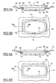
- FIGS. 5A and 5B show the cover 48 in an intermediate position during assembly
- FIGS. 6A and 6B show the cache'48 in mounted position.
- the cover 48 is mounted in the window 46 from the outside inward along the mounting axis A2. During the mounting operation, by moving the cover 48 axially inwards, the surfaces 78, 80 forming a ramp cooperate with the edge 86 of the window 46 so that the ring 70 deforms radially by compressing at the height of ramps, as can be seen in Figures 5A and 5B. The radial ends of ring 70 are then in radial support against the edge 86 of the window 46, and the cover 48 is in the intermediate position during assembly.
- the ring 70 When the cover 48 is in the mounted position, the ring 70 is in transverse support on the edge 86 of the window 46 by the radial end portions 88 of its lateral face peripheral 90, and it is in axial support on the inner face 16 of the panel 12 by its axial abutment surfaces 82.
- the cover 48 is axially supported on the outer face 20 of the panel 12 by its annular peripheral wall 50.
- the ring 70 axially retains the cover 48 inside the window 46 of the body panel 12.
- the dimensions of the ring 70 and of the window 46 are provided so that the ring 70 fits in the window frame 46 when it is distorted by the mounting operation.
- the ring 70 must be long enough axially so that the abutment surfaces 82 axial of its radial ends are vis-à-vis the face interior 16 of the body panel 12, in position climb.
- the window 46 is substantially shaped rectangular. But according to variants (not shown) of the invention, the window 46 can be of any other form allowing the ring 70 to fit into its frame and to rest axially on the inner face 16 of the panel 12.
- the ring 70 is mounted on the skirt tubular 52 with radial clearance to facilitate its deformation elastic and return to its original shape.
- the ring 70 is made of material natural or synthetic elastomer.
- a peripheral seal 92 is axially interposed between the cover 48 and the sensor 42. This seal is then in abutment axial oriented outwards on the transverse face 54 oriented towards the outside of the tubular skirt 52, and it presses the axial abutment surfaces 82 against the inner face 16 of the panel 12.
- the ring 70 is carried by the tubular skirt by any other known means, for example by bonding or by crimping.
Landscapes
- Lock And Its Accessories (AREA)
Applications Claiming Priority (3)
| Application Number | Priority Date | Filing Date | Title |
|---|---|---|---|
| FR9912674A FR2799491B1 (fr) | 1999-10-12 | 1999-10-12 | Systeme de securite pour un ouvrant de vehicule automobile comportant un cache de protection equipe d'une bague deformable de montage |
| FR9912674 | 1999-10-12 | ||
| PCT/FR2000/002803 WO2001027419A1 (fr) | 1999-10-12 | 2000-10-10 | Systeme de securite pour un ouvrant de vehicule automobile |
Publications (2)
| Publication Number | Publication Date |
|---|---|
| EP1144781A1 EP1144781A1 (fr) | 2001-10-17 |
| EP1144781B1 true EP1144781B1 (fr) | 2004-06-09 |
Family
ID=9550803
Family Applications (1)
| Application Number | Title | Priority Date | Filing Date |
|---|---|---|---|
| EP00967986A Expired - Lifetime EP1144781B1 (fr) | 1999-10-12 | 2000-10-10 | Systeme de securite pour un ouvrant de vehicule automobile |
Country Status (6)
| Country | Link |
|---|---|
| US (1) | US6518883B1 (enExample) |
| EP (1) | EP1144781B1 (enExample) |
| JP (1) | JP5202781B2 (enExample) |
| DE (1) | DE60011388T2 (enExample) |
| FR (1) | FR2799491B1 (enExample) |
| WO (1) | WO2001027419A1 (enExample) |
Families Citing this family (9)
| Publication number | Priority date | Publication date | Assignee | Title |
|---|---|---|---|---|
| FR2828225B1 (fr) * | 2001-08-01 | 2003-10-31 | Valeo Electronique | Poignee d'ouvrant pour vehicule automobile |
| DE10341402A1 (de) * | 2003-09-05 | 2005-04-07 | Brose Schließsysteme GmbH & Co.KG | Kraftfahrzeug-Türschließsystem und Türinnengriff |
| US7077452B2 (en) | 2004-11-12 | 2006-07-18 | Toyota Technical Center Usa, Inc. | Attachment of a panel to a soft instrument panel of an automotive vehicle |
| ITMI20062529A1 (it) * | 2006-12-28 | 2008-06-29 | Valeo Sicurezza Abitacolo Spa | Sensore per maniglie di veicoli |
| JP2010216176A (ja) * | 2009-03-18 | 2010-09-30 | Aisin Seiki Co Ltd | 車両用ドアハンドル装置 |
| JP5513442B2 (ja) * | 2011-05-27 | 2014-06-04 | 株式会社ホンダロック | 車両用ドアのアウトハンドル装置 |
| EP3023303B1 (en) * | 2014-11-21 | 2017-06-14 | FCA Italy S.p.A. | Movable loading floor for a motor vehicle trunk |
| EP3939021A1 (en) * | 2019-03-14 | 2022-01-19 | IEE International Electronics & Engineering S.A. | Vehicle occupant detection |
| US11117500B2 (en) * | 2019-11-01 | 2021-09-14 | Ts Tech Co., Ltd. | Vehicle seat |
Family Cites Families (10)
| Publication number | Priority date | Publication date | Assignee | Title |
|---|---|---|---|---|
| JPH0384372U (enExample) * | 1989-12-19 | 1991-08-27 | ||
| DE4228234A1 (de) * | 1992-08-25 | 1994-03-03 | Bayerische Motoren Werke Ag | Türschloß für Kraftfahrzeuge |
| DE19516316C2 (de) * | 1995-05-04 | 1998-11-26 | Kiekert Ag | Sicherheitseinrichtung an einem Kraftfahrzeug, welche lediglich einer zum Öffnen des Kraftfahrzeuges berechtigten Person das Öffnen des Kraftfahrzeuges erlaubt |
| JPH094292A (ja) * | 1995-06-17 | 1997-01-07 | Omron Corp | 施解錠装置及び施解錠システム |
| JPH10292702A (ja) * | 1997-04-21 | 1998-11-04 | Aisin Seiki Co Ltd | ドア近接通信装置およびドアロック制御装置 |
| IT1294881B1 (it) * | 1997-09-23 | 1999-04-23 | Valeo Sicurezza Abitacolo Spa | Maniglia per una porta di un veicolo. |
| FR2772818B1 (fr) * | 1997-12-23 | 2000-01-21 | Valeo Securite Habitacle | Systeme de securite pour un ouvrant de vehicule automobile |
| FR2781247B1 (fr) * | 1998-07-17 | 2000-08-18 | Valeo Securite Habitacle | Systeme de securite pour un ouvrant de vehicule automobile comportant un cache de protection |
| FR2781246B1 (fr) * | 1998-07-17 | 2000-08-18 | Valeo Securite Habitacle | Systeme de securite pour un ouvrant de vehicule automobile comportant des moyens de raccordement perfectionnes |
| FR2789433B1 (fr) * | 1999-02-05 | 2001-04-13 | Valeo Securite Habitacle | Systeme de securite pour un ouvrant de vehicule automobile |
-
1999
- 1999-10-12 FR FR9912674A patent/FR2799491B1/fr not_active Expired - Fee Related
-
2000
- 2000-10-10 DE DE60011388T patent/DE60011388T2/de not_active Expired - Lifetime
- 2000-10-10 WO PCT/FR2000/002803 patent/WO2001027419A1/fr not_active Ceased
- 2000-10-10 JP JP2001529538A patent/JP5202781B2/ja not_active Expired - Fee Related
- 2000-10-10 US US09/857,941 patent/US6518883B1/en not_active Expired - Lifetime
- 2000-10-10 EP EP00967986A patent/EP1144781B1/fr not_active Expired - Lifetime
Also Published As
| Publication number | Publication date |
|---|---|
| DE60011388D1 (de) | 2004-07-15 |
| EP1144781A1 (fr) | 2001-10-17 |
| FR2799491A1 (fr) | 2001-04-13 |
| WO2001027419A1 (fr) | 2001-04-19 |
| JP5202781B2 (ja) | 2013-06-05 |
| JP2003511594A (ja) | 2003-03-25 |
| DE60011388T2 (de) | 2005-06-23 |
| FR2799491B1 (fr) | 2001-12-07 |
| US6518883B1 (en) | 2003-02-11 |
Similar Documents
| Publication | Publication Date | Title |
|---|---|---|
| EP0972897B1 (fr) | Systeme de securite pour un ouvrant de vehicule automobile comportant un cache de protection | |
| EP1026348B1 (fr) | Système de sécurité pour un ouvrant de véhicule automobile | |
| EP1144781B1 (fr) | Systeme de securite pour un ouvrant de vehicule automobile | |
| EP1390241B1 (fr) | Module d'equipement de vehicule automobile | |
| EP0545813B1 (fr) | Dispositif pour la fermeture de la canalisation de remplissage du réservoir de carburant d'un véhicule automobile | |
| EP2861472B1 (fr) | Balai d'essuyage a connecteur hydraulique | |
| FR2684051A1 (fr) | Dispositif d'etancheite pour panneaux transparents affleurant sur une carrosserie de vehicule. | |
| FR2892993A1 (fr) | Dispositif aerodynamique pour un vehicule automobile et vehicule automobile comportant au moins un tel dispositif aerodynamique. | |
| WO2009059904A1 (fr) | Agencement de montage d'un joint de cardan de connexion du barillet d'un verrou sur une serrure | |
| EP0972898B1 (fr) | Systeme de securite pour un ouvrant de vehicule automobile comportant des moyens de raccordement perfectionnes | |
| EP0742329B1 (fr) | Dispositif de verrouillage d'un ouvrant de véhicule automobile comportant des moyens perfectionnés de montage d'un capuchon d'habillage | |
| EP0296961B1 (fr) | Dispositif de fixation | |
| EP0628455A1 (fr) | Antivol de direction pour véhicule automobile | |
| EP1255007B1 (fr) | Dispositif de verrouillage pour ouvrant de véhicule automobile et agencement de ce dispositif sur une paroi de cet ouvrant | |
| EP1892130A1 (fr) | Dispositif de fixation supérieure d'un amortisseur de suspension sur la caisse d'un véhicule | |
| EP1126196B1 (fr) | Carter de boíte de vitesses manuelle pour véhicule automobile | |
| FR2567817A1 (fr) | Commande de debrayage pour vehicule automobile, equipee d'un ressort d'assistance | |
| EP0457633B1 (fr) | Dispositif de fixation d'un verrou dans une poignée de portière, notamment d'un véhicule automobile | |
| EP0251844B1 (fr) | Poignée de porte à palette basculante | |
| EP1108950B1 (fr) | Projecteur de véhicule automobile comprenant des moyens perfectionnés de verouillage de lampe | |
| FR2821907A1 (fr) | Dispositif de securite pour la protection d'un moteur d'essuie-glace | |
| FR3100180A1 (fr) | Contacteur tournant pour ensemble de commutation de haut de colonne de véhicule. | |
| FR2629885A1 (fr) | Montage de butee de debrayage, notamment pour vehicule automobile | |
| FR2780925A1 (fr) | Commutateur de clignotants avec un dispositif de rappel a echappement | |
| EP0731243B1 (fr) | Verrou à rotor débrayable et antivol de direction de véhicule automobile équipé d'un tel verrou |
Legal Events
| Date | Code | Title | Description |
|---|---|---|---|
| PUAI | Public reference made under article 153(3) epc to a published international application that has entered the european phase |
Free format text: ORIGINAL CODE: 0009012 |
|
| AK | Designated contracting states |
Kind code of ref document: A1 Designated state(s): AT BE CH CY DE DK ES FI FR GB GR IE IT LI LU MC NL PT SE |
|
| AX | Request for extension of the european patent |
Free format text: AL;LT;LV;MK;RO;SI |
|
| 17P | Request for examination filed |
Effective date: 20011019 |
|
| GRAP | Despatch of communication of intention to grant a patent |
Free format text: ORIGINAL CODE: EPIDOSNIGR1 |
|
| RAP1 | Party data changed (applicant data changed or rights of an application transferred) |
Owner name: VALEO SECURITE HABITACLE S.A.S. |
|
| GRAS | Grant fee paid |
Free format text: ORIGINAL CODE: EPIDOSNIGR3 |
|
| GRAA | (expected) grant |
Free format text: ORIGINAL CODE: 0009210 |
|
| AK | Designated contracting states |
Kind code of ref document: B1 Designated state(s): DE ES FR GB IT |
|
| REG | Reference to a national code |
Ref country code: GB Ref legal event code: FG4D Free format text: NOT ENGLISH |
|
| GBT | Gb: translation of ep patent filed (gb section 77(6)(a)/1977) |
Effective date: 20040609 |
|
| REF | Corresponds to: |
Ref document number: 60011388 Country of ref document: DE Date of ref document: 20040715 Kind code of ref document: P |
|
| REG | Reference to a national code |
Ref country code: IE Ref legal event code: FG4D Free format text: FRENCH |
|
| PG25 | Lapsed in a contracting state [announced via postgrant information from national office to epo] |
Ref country code: ES Free format text: LAPSE BECAUSE OF FAILURE TO SUBMIT A TRANSLATION OF THE DESCRIPTION OR TO PAY THE FEE WITHIN THE PRESCRIBED TIME-LIMIT Effective date: 20040920 |
|
| LTIE | Lt: invalidation of european patent or patent extension |
Effective date: 20040609 |
|
| REG | Reference to a national code |
Ref country code: IE Ref legal event code: FD4D |
|
| PLBE | No opposition filed within time limit |
Free format text: ORIGINAL CODE: 0009261 |
|
| STAA | Information on the status of an ep patent application or granted ep patent |
Free format text: STATUS: NO OPPOSITION FILED WITHIN TIME LIMIT |
|
| 26N | No opposition filed |
Effective date: 20050310 |
|
| PGFP | Annual fee paid to national office [announced via postgrant information from national office to epo] |
Ref country code: FR Payment date: 20111118 Year of fee payment: 12 |
|
| REG | Reference to a national code |
Ref country code: FR Ref legal event code: ST Effective date: 20130628 |
|
| PG25 | Lapsed in a contracting state [announced via postgrant information from national office to epo] |
Ref country code: FR Free format text: LAPSE BECAUSE OF NON-PAYMENT OF DUE FEES Effective date: 20121031 |
|
| PGFP | Annual fee paid to national office [announced via postgrant information from national office to epo] |
Ref country code: DE Payment date: 20131004 Year of fee payment: 14 Ref country code: GB Payment date: 20131010 Year of fee payment: 14 |
|
| PGFP | Annual fee paid to national office [announced via postgrant information from national office to epo] |
Ref country code: IT Payment date: 20131011 Year of fee payment: 14 |
|
| REG | Reference to a national code |
Ref country code: DE Ref legal event code: R119 Ref document number: 60011388 Country of ref document: DE |
|
| GBPC | Gb: european patent ceased through non-payment of renewal fee |
Effective date: 20141010 |
|
| PG25 | Lapsed in a contracting state [announced via postgrant information from national office to epo] |
Ref country code: DE Free format text: LAPSE BECAUSE OF NON-PAYMENT OF DUE FEES Effective date: 20150501 Ref country code: GB Free format text: LAPSE BECAUSE OF NON-PAYMENT OF DUE FEES Effective date: 20141010 |
|
| PG25 | Lapsed in a contracting state [announced via postgrant information from national office to epo] |
Ref country code: IT Free format text: LAPSE BECAUSE OF NON-PAYMENT OF DUE FEES Effective date: 20141010 |