EP1143837B1 - Kaffeebrüher - Google Patents
Kaffeebrüher Download PDFInfo
- Publication number
- EP1143837B1 EP1143837B1 EP99970842A EP99970842A EP1143837B1 EP 1143837 B1 EP1143837 B1 EP 1143837B1 EP 99970842 A EP99970842 A EP 99970842A EP 99970842 A EP99970842 A EP 99970842A EP 1143837 B1 EP1143837 B1 EP 1143837B1
- Authority
- EP
- European Patent Office
- Prior art keywords
- cylinder
- lid
- base
- coffee machine
- disposed
- Prior art date
- Legal status (The legal status is an assumption and is not a legal conclusion. Google has not performed a legal analysis and makes no representation as to the accuracy of the status listed.)
- Expired - Lifetime
Links
Images

Classifications
-
- A—HUMAN NECESSITIES
- A47—FURNITURE; DOMESTIC ARTICLES OR APPLIANCES; COFFEE MILLS; SPICE MILLS; SUCTION CLEANERS IN GENERAL
- A47J—KITCHEN EQUIPMENT; COFFEE MILLS; SPICE MILLS; APPARATUS FOR MAKING BEVERAGES
- A47J31/00—Apparatus for making beverages
- A47J31/002—Apparatus for making beverages following a specific operational sequence, e.g. for improving the taste of the extraction product
-
- A—HUMAN NECESSITIES
- A47—FURNITURE; DOMESTIC ARTICLES OR APPLIANCES; COFFEE MILLS; SPICE MILLS; SUCTION CLEANERS IN GENERAL
- A47J—KITCHEN EQUIPMENT; COFFEE MILLS; SPICE MILLS; APPARATUS FOR MAKING BEVERAGES
- A47J31/00—Apparatus for making beverages
- A47J31/18—Apparatus in which ground coffee or tea-leaves are immersed in the hot liquid in the beverage container
Definitions
- the invention relates to a coffee brewer according to the preamble of Claim 1.
- Such a coffee brewer is known from EP 0 627 187 B1, which has two cylinders arranged side by side, each one Form the brewing chamber.
- the cylinders are covered by a closing element closed, the movable in a horizontal guide is.
- the lower end of the cylinder is also in two horizontally displaceable pistons closed, each carry an extraction strainer.
- the cylinders are initially seated over the piston so that they dip into the cylinder.
- the height the piston is sized so that it is at its upper end arranged extraction screens in a final position, in which the Cylinders are moved all the way down in the vertical direction with Align the top of the cylinder so that used coffee grounds can be stripped.
- the cylinders will be vertical Directed up to form a cavity that ultimately represents the brewing chamber.
- ground coffee is poured into measured portions from above.
- the closing element is then moved forward so that it is positioned over the cylinders.
- a spray tube is provided for each cylinder, through the brewing water can be introduced into the brewing chambers thus formed.
- the cylinders are only vertical Direction moves while the movements of the closing element and the piston only in the horizontal direction and thus orthogonal to Cylinder movement takes place.
- the object of the invention is to provide a new type of coffee brewer create, in which the movement relationships of cylinder, cover and soil are different than in the prior art, in order for only one Drive motor to achieve a lower overall height.
- the coffee brewer is used at the beginning mentioned type of the characterizing features of the claim 1 has.
- This new construction means that the lid and bottom are not in the right angle shifted relative to the cylinder, but over a The booms are first folded up and then in guides withdrawn.
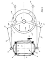
- FIG. 1 shows a cylinder 2 which is closed at its upper end by a cover 4 and at its lower end by a base 6.
- the cylinder 2 closed in this way thereby forms a brewing chamber 8 for brewing a coffee beverage from ground coffee and hot water.
- the lid 4 open the ground coffee is filled into the brewing chamber 8 from above and falls onto an extraction sieve 22 which is arranged in the base 6.
- There is a cavity under the extraction sieve 22 which merges into a beverage outlet (not shown) so that the coffee beverage can flow away as a result.
- a sealing ring 28 ' is placed around the extraction sieve 22 and seals the lower edge of the cylinder 2 in the closed state.
- a sieve plate 27 is arranged, which the brewing water in introduces the type of a shower into the brewing chamber 8.
- a sealing ring 28 To the Sieve plate 27 is in turn placed a sealing ring 28, the Seals the upper edge of the cylinder 2 in the closed state.
- the Cam 112 has a first in its right part semicircular section 120 with a first radius to which in the left part a second semicircular section 120 ' larger radius over transition areas and thus one Control backdrop 122 forms.
- the backdrop 122 is in one version a groove machined into cam 112 on one side, from which the partial circle line or half the height is fully drawn Line is drawn.
- rollers 130 and 130 ' the centers of which run in the backdrop 122 accordingly lie on the pitch circle contour of the backdrop 122.
- the Rollers 130, 130 ' are on an upper or lower linkage 100, 100 'rotatably mounted so that the linkage 100, 100' depending Can raise or lower the position of the cam 112. Around this is made possible by the right ends of the rods 100, 100 ' at fixed upper and lower pivot points 70, 70 ' appropriate.
- the fixed upper and lower pivot points 70, 70 ' of the linkages 100, 100 ' form one-armed levers, which with their Right ends hinged to the fixed pivot points 70, 70 ' are and through the cam 112 on the rollers 130, 130 ' Lift off cover 4 or base 6 from cylinder 2, as the others Ends via first and second joints 3, 3 'with the cover 3 and the Bottom 4 are connected.
- FIG. 1 also shows a first retraction lever 19 which is freely rotatable on the shaft 15 of a control disk and which is coupled to the cover 4 via a fourth joint 18 and a pull rod 21 via the first joint 3.
- a second retraction lever 19 ' is rotatably arranged on the shaft 15 and coupled to the floor 6 via a fourth joint 18' and a pull rod 21 ', specifically via the first joint 3'.
- FIG. 1 also shows a first actuating pin 119 for rotating the first retraction lever 19 clockwise around the shaft 15, while a second actuating pin 119 'rotates it counterclockwise around the shaft 15 when the second retraction lever 19' is touched.
- the two actuating pins 119 and 119 ' are mounted at a suitable point on the cam plate 112 and project from it in the axial direction, namely to the extent that they take the retraction levers 19, 19' with them when they are touched and clockwise or counterclockwise around the shaft 15 can pivot. It is clear to the person skilled in the art that the actuating pins 119, 119 'for this purpose must not be arranged in such a way that they hinder the function of the cam disk 112.
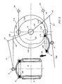
- FIG. 2 shows the embodiment of the invention in which the cam disk 112 is rotated counterclockwise by a motor (not shown) that drives the shaft 15 by an angle of rotation of 35 ° in the direction of arrow B.
- the second actuating pin 119 ' comes into contact with the second retraction lever 19' and takes this with a further rotation of the cam plate 112 to a position as shown as the end position in FIG. 3 .
- FIG. 2 thus demonstrates the maximum opening of the base 6 in relation to the cylinder 2, namely immediately before the base 6 is pulled back from the cylinder 2.
- FIG. 3 finally shows the embodiment in the end position of the second pull-back lever 19 ', which has pulled the base 6 back as far as possible from the cylinder 2 at a rotation angle of 97 °, in the embodiment shown beyond the stripper 29, so that the coffee grounds remaining on the floor 6 after the brewing process could be completely stripped off.
- the bottom 6 is tilted above all when it is moved past a scraper 29 in the manner shown in FIG. 3 .
- the wiper 29 is mounted on the lower linkage 10 'via a wiper holder, not shown.
- retraction lever 19, 19 'through a coil spring mounted around the shaft 15 or by a Coil spring can be turned into position cylinder 2 to cover 4 or bottom 6 after pulling back from cylinder 2 in To move towards cylinder 2.
Description
- Figur 1
- ein Ausführungsbeispiel in der Ausgangsstellung;
- Figur 2
- das Ausführungsbeispiel bei einem Drehwinkel von 35°; und
- Figur 3
- das Ausführungsbeispiel bei einem Drehwinkel von 97°.
Claims (8)
- Kaffeebrüher mit einem Gehäuse in dem ein Zylinder (2) angeordnet ist, dessen oberes Ende durch einen Deckel (4) und dessen unteres Ende durch einen Boden (6) verschließbar ist, so daß im geschlossenen Zustand eine Brühkammer (8) für die Aufnahme von Kaffeemehl und Brühwasser gebildet wird, wobei zum Öffnen der Brühkammer (8) sowohl der Boden (6) als auch der Deckel (4) von dem Zylinder (2) entfernt werden können und wobei in dem Deckel (4) ein Wassereinlaß und in dem Boden (6) ein Extraktionssieb und ein Getränkeauslaß angeordnet sind, dadurch gekennzeichnet, daß der Deckel (4) und der Boden (6) von einem oberen bzw. unteren Gestänge (100, 100') jeweils um einen festliegenden oberen bzw. unteren Drehpunkt (70, 70') durch Drehen einer Kurvenscheibe (112) schwenkbar sind, die eine Steuerungs-Kulisse (122) aufweist, mit der sie bei einer Drehung um ihre Achse das Gestänge (100, 100') vom Zylinder (2) abhebt oder gegen diesen drückt.
- Brüher nach Anspruch 1, dadurch gekennzeichnet, daß auf der Achse einer Steuerscheibe zwei schwenkbare Rückziehhebel (19, 19') angeordnet sind, die über je ein viertes Gelenk (18, 18') und je eine Zugstange (21, 21') mit dem Deckel (4) bzw. dem Boden (6) gekoppelt sind.
- Brüher nach Anspruch 1, dadurch gekennzeichnet, daß das obere und untere Gestänge (100, 100') mit je einer Schiene für das Zurückziehen des Deckels (4) und des Bodens (6) ausgerüstet sind, die ebenfalls um die Drehpunkte (70, 70') schwenkbar sind.
- Brüher nach Anspruch 1, dadurch gekennzeichnet, daß die Kurvenscheibe (112) nahezu mittig zwischen dem oberen und dem unteren Gestänge (100, 100') angeordnet ist.
- Brüher nach Anspruch 2, dadurch gekennzeichnet, daß die Rückziehhebel (19, 19') durch Kontakt mit einem auf der Kurvenscheibe (112) angeordneten Zapfen (119, 119') um die Welle (15) schwenkbar und durch Zugfedern, Druckfedern oder Drehfedern in ihre Ausgangsstellungen zurück bewegbar sind.
- Brüher nach Anspruch 1, dadurch gekennzeichnet, daß in der Nähe des Bodens (6) ein Abstreifer (29) für verbrauchtes Kaffeemehl angeordnet ist.
- Brüher nach Anspruch 2, dadurch gekennzeichnet, daß das obere und untere Gestänge (100, 100') über je eine Rolle (130, 130') mit der Kurvenscheibe (112) in Eingriff stehen.
- Brüher nach Anspruch 7, dadurch gekennzeichnet, daß die Rollen (130, 130') in einer Nut der Kurvenscheibe (112) laufen, wobei die Nut eine Steuerungs-Kulisse (122) bildet.
Applications Claiming Priority (3)
| Application Number | Priority Date | Filing Date | Title |
|---|---|---|---|
| DE19852531 | 1998-11-06 | ||
| DE19852531A DE19852531C1 (de) | 1998-11-06 | 1998-11-06 | Kaffeebrüher |
| PCT/EP1999/008271 WO2000028867A2 (de) | 1998-11-06 | 1999-11-02 | Kaffeebrüher |
Publications (2)
| Publication Number | Publication Date |
|---|---|
| EP1143837A2 EP1143837A2 (de) | 2001-10-17 |
| EP1143837B1 true EP1143837B1 (de) | 2003-09-24 |
Family
ID=7887776
Family Applications (1)
| Application Number | Title | Priority Date | Filing Date |
|---|---|---|---|
| EP99970842A Expired - Lifetime EP1143837B1 (de) | 1998-11-06 | 1999-11-02 | Kaffeebrüher |
Country Status (6)
| Country | Link |
|---|---|
| EP (1) | EP1143837B1 (de) |
| AT (1) | ATE250378T1 (de) |
| CZ (1) | CZ20011595A3 (de) |
| DE (2) | DE19852531C1 (de) |
| PL (1) | PL348912A1 (de) |
| WO (1) | WO2000028867A2 (de) |
Families Citing this family (3)
| Publication number | Priority date | Publication date | Assignee | Title |
|---|---|---|---|---|
| DE10213514C1 (de) * | 2002-03-26 | 2003-11-27 | Michael Kaatze | Kaffeebrüher |
| ES2458229T3 (es) | 2010-07-14 | 2014-04-30 | Unilever Nv | Procedimiento de realización de la infusión de una bebida y cartucho que contiene material para infusión |
| EP2592979B1 (de) | 2010-07-14 | 2015-01-21 | Unilever N.V. | Getränkezubereitungsvorrichtung und -verfahren |
Citations (1)
| Publication number | Priority date | Publication date | Assignee | Title |
|---|---|---|---|---|
| EP0627187A1 (de) * | 1993-06-03 | 1994-12-07 | Maas Mechatronics B.V. | Verfahren und Vorrichtung zur Bereitung eines Extrakts aus einem extraktierbaren Ausgangsmaterial |
Family Cites Families (3)
| Publication number | Priority date | Publication date | Assignee | Title |
|---|---|---|---|---|
| US3103873A (en) * | 1959-12-31 | 1963-09-17 | Seeburg Corp | High-speed beverage brewer |
| IT1236088B (it) * | 1989-11-28 | 1992-12-22 | Spidem Srl | Metodo per ottenere bevande calde di soluzione e dispositivo per attuare il detto metodo |
| IT1289399B1 (it) * | 1996-11-06 | 1998-10-02 | Electrolux Zanussi Vending Spa | Metodo migliorato e macchina automatica per preparare bevande calde monodose quali caffe' e simili |
-
1998
- 1998-11-06 DE DE19852531A patent/DE19852531C1/de not_active Expired - Fee Related
-
1999
- 1999-11-02 PL PL99348912A patent/PL348912A1/xx unknown
- 1999-11-02 CZ CZ20011595A patent/CZ20011595A3/cs unknown
- 1999-11-02 EP EP99970842A patent/EP1143837B1/de not_active Expired - Lifetime
- 1999-11-02 DE DE59907135T patent/DE59907135D1/de not_active Expired - Fee Related
- 1999-11-02 WO PCT/EP1999/008271 patent/WO2000028867A2/de not_active Application Discontinuation
- 1999-11-02 AT AT99970842T patent/ATE250378T1/de not_active IP Right Cessation
Patent Citations (1)
| Publication number | Priority date | Publication date | Assignee | Title |
|---|---|---|---|---|
| EP0627187A1 (de) * | 1993-06-03 | 1994-12-07 | Maas Mechatronics B.V. | Verfahren und Vorrichtung zur Bereitung eines Extrakts aus einem extraktierbaren Ausgangsmaterial |
Also Published As
| Publication number | Publication date |
|---|---|
| CZ20011595A3 (cs) | 2001-11-14 |
| PL348912A1 (en) | 2002-06-17 |
| DE19852531C1 (de) | 2000-04-13 |
| EP1143837A2 (de) | 2001-10-17 |
| WO2000028867A3 (de) | 2001-10-11 |
| ATE250378T1 (de) | 2003-10-15 |
| DE59907135D1 (de) | 2003-10-30 |
| WO2000028867A2 (de) | 2000-05-25 |
Similar Documents
| Publication | Publication Date | Title |
|---|---|---|
| DE2317341C3 (de) | Lukendeckel-Verschlußvorrichtung | |
| DE3152397C1 (de) | Verfahren und Kaffeemaschine zur Herstellung von Kaffee | |
| EP0528758B1 (de) | Vorrichtung zum Ausstossen von zu einem Kuchen gepresstem Kaffeepulver aus einer Brüheinrichtung einer Kaffeemaschine | |
| EP0328744B1 (de) | Getränkezubereitungsmaschine | |
| DE1454102B2 (de) | Selbsttaetige kaffeemaschine zur portionsweisen zubereitung von espresso kaffee | |
| DE4318113C1 (de) | Brühgetränkemaschine | |
| EP1143837B1 (de) | Kaffeebrüher | |
| DE3617309C2 (de) | ||
| DE2945360A1 (de) | Automatische kaffeemaschine | |
| EP3545801B1 (de) | Getränkezubereitungsmaschine mit restwasserdrainage | |
| CH662858A5 (de) | Saeule mit daran befestigten vorrichtungen. | |
| DE4203088A1 (de) | Bruehgruppe fuer eine kaffeemaschine | |
| EP0004337B1 (de) | Einrichtung zum Entwickeln von Druckplatten mit paarweise horizontal angeordneten oberen und unteren Walzen | |
| DE3151238A1 (de) | Vorrichtung zum fuehren des faltmessers und zum betaetigen des kipparmes des messerbalkens einer plissiermaschine | |
| EP0864284B1 (de) | Kaffeemaschine | |
| DE10213514C1 (de) | Kaffeebrüher | |
| DE19515298C2 (de) | Drückerfußanordnung | |
| EP1502527B1 (de) | Brühvorrichtung mit axial wirkendem Gewindemechanismus | |
| DE333096C (de) | Verfahren und Vorrichtung zur Herstellung eines dichten Verschlusses an Flaschen u. dgl. | |
| DE2755862A1 (de) | Gummierautomat | |
| DE1454102C (de) | Selbsttätige Kaffeemaschine zur portionsweisen Zubereitung von Espresso-Kaffee | |
| DE1295143B (de) | Bruehvorrichtung fuer Kaffeemaschinen od. dgl. | |
| CH651741A5 (de) | Kaffeemaschine. | |
| DE3542924A1 (de) | Spender fuer pastoese produkte | |
| DE2155832C3 (de) | Sicherungskupplung für einen Kernreaktor-Steuerstab |
Legal Events
| Date | Code | Title | Description |
|---|---|---|---|
| PUAI | Public reference made under article 153(3) epc to a published international application that has entered the european phase |
Free format text: ORIGINAL CODE: 0009012 |
|
| 17P | Request for examination filed |
Effective date: 20010612 |
|
| AK | Designated contracting states |
Kind code of ref document: A2 Designated state(s): AT BE CH CY DE DK ES FI FR GB GR IE IT LI LU MC NL PT SE |
|
| XX | Miscellaneous (additional remarks) |
Free format text: DERZEIT SIND DIE WIPO-PUBLIKATIONSDATEN A3 NICHT VERFUEGBAR. |
|
| PUAK | Availability of information related to the publication of the international search report |
Free format text: ORIGINAL CODE: 0009015 |
|
| AK | Designated contracting states |
Kind code of ref document: A3 Designated state(s): AT BE CH CY DE DK ES FI FR GB GR IE IT LI LU MC NL PT SE |
|
| RIC1 | Information provided on ipc code assigned before grant |
Free format text: 7A 47J 31/40 A |
|
| 17Q | First examination report despatched |
Effective date: 20020219 |
|
| GRAH | Despatch of communication of intention to grant a patent |
Free format text: ORIGINAL CODE: EPIDOS IGRA |
|
| GRAS | Grant fee paid |
Free format text: ORIGINAL CODE: EPIDOSNIGR3 |
|
| GRAA | (expected) grant |
Free format text: ORIGINAL CODE: 0009210 |
|
| AK | Designated contracting states |
Kind code of ref document: B1 Designated state(s): AT BE CH CY DE DK ES FI FR GB GR IE IT LI LU MC NL PT SE |
|
| PG25 | Lapsed in a contracting state [announced via postgrant information from national office to epo] |
Ref country code: IT Free format text: LAPSE BECAUSE OF FAILURE TO SUBMIT A TRANSLATION OF THE DESCRIPTION OR TO PAY THE FEE WITHIN THE PRESCRIBED TIME-LIMIT;WARNING: LAPSES OF ITALIAN PATENTS WITH EFFECTIVE DATE BEFORE 2007 MAY HAVE OCCURRED AT ANY TIME BEFORE 2007. THE CORRECT EFFECTIVE DATE MAY BE DIFFERENT FROM THE ONE RECORDED. Effective date: 20030924 Ref country code: IE Free format text: LAPSE BECAUSE OF FAILURE TO SUBMIT A TRANSLATION OF THE DESCRIPTION OR TO PAY THE FEE WITHIN THE PRESCRIBED TIME-LIMIT Effective date: 20030924 Ref country code: GB Free format text: LAPSE BECAUSE OF FAILURE TO SUBMIT A TRANSLATION OF THE DESCRIPTION OR TO PAY THE FEE WITHIN THE PRESCRIBED TIME-LIMIT Effective date: 20030924 Ref country code: FR Free format text: LAPSE BECAUSE OF FAILURE TO SUBMIT A TRANSLATION OF THE DESCRIPTION OR TO PAY THE FEE WITHIN THE PRESCRIBED TIME-LIMIT Effective date: 20030924 Ref country code: FI Free format text: LAPSE BECAUSE OF FAILURE TO SUBMIT A TRANSLATION OF THE DESCRIPTION OR TO PAY THE FEE WITHIN THE PRESCRIBED TIME-LIMIT Effective date: 20030924 |
|
| REG | Reference to a national code |
Ref country code: GB Ref legal event code: FG4D Free format text: NOT ENGLISH |
|
| XX | Miscellaneous (additional remarks) |
Free format text: DERZEIT SIND DIE WIPO-PUBLIKATIONSDATEN A3 NICHT VERFUEGBAR. |
|
| REG | Reference to a national code |
Ref country code: CH Ref legal event code: EP |
|
| REG | Reference to a national code |
Ref country code: IE Ref legal event code: FG4D Free format text: GERMAN |
|
| REF | Corresponds to: |
Ref document number: 59907135 Country of ref document: DE Date of ref document: 20031030 Kind code of ref document: P |
|
| PG25 | Lapsed in a contracting state [announced via postgrant information from national office to epo] |
Ref country code: LU Free format text: LAPSE BECAUSE OF NON-PAYMENT OF DUE FEES Effective date: 20031102 Ref country code: CY Free format text: LAPSE BECAUSE OF FAILURE TO SUBMIT A TRANSLATION OF THE DESCRIPTION OR TO PAY THE FEE WITHIN THE PRESCRIBED TIME-LIMIT Effective date: 20031102 |
|
| PG25 | Lapsed in a contracting state [announced via postgrant information from national office to epo] |
Ref country code: MC Free format text: LAPSE BECAUSE OF NON-PAYMENT OF DUE FEES Effective date: 20031130 Ref country code: BE Free format text: LAPSE BECAUSE OF NON-PAYMENT OF DUE FEES Effective date: 20031130 |
|
| PGFP | Annual fee paid to national office [announced via postgrant information from national office to epo] |
Ref country code: NL Payment date: 20031130 Year of fee payment: 5 |
|
| PG25 | Lapsed in a contracting state [announced via postgrant information from national office to epo] |
Ref country code: SE Free format text: LAPSE BECAUSE OF FAILURE TO SUBMIT A TRANSLATION OF THE DESCRIPTION OR TO PAY THE FEE WITHIN THE PRESCRIBED TIME-LIMIT Effective date: 20031224 Ref country code: GR Free format text: LAPSE BECAUSE OF FAILURE TO SUBMIT A TRANSLATION OF THE DESCRIPTION OR TO PAY THE FEE WITHIN THE PRESCRIBED TIME-LIMIT Effective date: 20031224 Ref country code: DK Free format text: LAPSE BECAUSE OF FAILURE TO SUBMIT A TRANSLATION OF THE DESCRIPTION OR TO PAY THE FEE WITHIN THE PRESCRIBED TIME-LIMIT Effective date: 20031224 |
|
| PG25 | Lapsed in a contracting state [announced via postgrant information from national office to epo] |
Ref country code: ES Free format text: LAPSE BECAUSE OF FAILURE TO SUBMIT A TRANSLATION OF THE DESCRIPTION OR TO PAY THE FEE WITHIN THE PRESCRIBED TIME-LIMIT Effective date: 20040104 |
|
| GBV | Gb: ep patent (uk) treated as always having been void in accordance with gb section 77(7)/1977 [no translation filed] |
Effective date: 20030924 |
|
| REG | Reference to a national code |
Ref country code: CH Ref legal event code: PUE Owner name: MICHAEL KAATZE Free format text: TCHIBO FRISCH-ROEST-KAFFEE GMBH#UEBERSEERING 18#22297 HAMBURG (DE) -TRANSFER TO- MICHAEL KAATZE#KIEFERNWEG 11#21255 TOSTEDT (DE) Ref country code: CH Ref legal event code: NV Representative=s name: BOVARD AG PATENTANWAELTE |
|
| REG | Reference to a national code |
Ref country code: IE Ref legal event code: FD4D |
|
| BERE | Be: lapsed |
Owner name: *TCHIBO FRISCH-ROST-KAFFEE G.M.B.H. Effective date: 20031130 |
|
| NLS | Nl: assignments of ep-patents |
Owner name: MICHAEL KAATZE |
|
| PLBE | No opposition filed within time limit |
Free format text: ORIGINAL CODE: 0009261 |
|
| STAA | Information on the status of an ep patent application or granted ep patent |
Free format text: STATUS: NO OPPOSITION FILED WITHIN TIME LIMIT |
|
| 26N | No opposition filed |
Effective date: 20040625 |
|
| PGFP | Annual fee paid to national office [announced via postgrant information from national office to epo] |
Ref country code: AT Payment date: 20040929 Year of fee payment: 6 |
|
| EN | Fr: translation not filed | ||
| PGFP | Annual fee paid to national office [announced via postgrant information from national office to epo] |
Ref country code: CH Payment date: 20041109 Year of fee payment: 6 |
|
| PGFP | Annual fee paid to national office [announced via postgrant information from national office to epo] |
Ref country code: DE Payment date: 20050203 Year of fee payment: 6 |
|
| PG25 | Lapsed in a contracting state [announced via postgrant information from national office to epo] |
Ref country code: NL Free format text: LAPSE BECAUSE OF NON-PAYMENT OF DUE FEES Effective date: 20050601 |
|
| NLV4 | Nl: lapsed or anulled due to non-payment of the annual fee |
Effective date: 20050601 |
|
| PG25 | Lapsed in a contracting state [announced via postgrant information from national office to epo] |
Ref country code: AT Free format text: LAPSE BECAUSE OF NON-PAYMENT OF DUE FEES Effective date: 20051102 |
|
| PG25 | Lapsed in a contracting state [announced via postgrant information from national office to epo] |
Ref country code: LI Free format text: LAPSE BECAUSE OF NON-PAYMENT OF DUE FEES Effective date: 20051130 Ref country code: CH Free format text: LAPSE BECAUSE OF NON-PAYMENT OF DUE FEES Effective date: 20051130 |
|
| PG25 | Lapsed in a contracting state [announced via postgrant information from national office to epo] |
Ref country code: DE Free format text: LAPSE BECAUSE OF NON-PAYMENT OF DUE FEES Effective date: 20060601 |
|
| REG | Reference to a national code |
Ref country code: CH Ref legal event code: PL |
|
| PG25 | Lapsed in a contracting state [announced via postgrant information from national office to epo] |
Ref country code: PT Free format text: LAPSE BECAUSE OF NON-PAYMENT OF DUE FEES Effective date: 20040224 |