EP1143386A1 - Dispositif de passage - Google Patents
Dispositif de passage Download PDFInfo
- Publication number
- EP1143386A1 EP1143386A1 EP00107452A EP00107452A EP1143386A1 EP 1143386 A1 EP1143386 A1 EP 1143386A1 EP 00107452 A EP00107452 A EP 00107452A EP 00107452 A EP00107452 A EP 00107452A EP 1143386 A1 EP1143386 A1 EP 1143386A1
- Authority
- EP
- European Patent Office
- Prior art keywords
- passage
- door leaf
- door
- frame
- partition
- Prior art date
- Legal status (The legal status is an assumption and is not a legal conclusion. Google has not performed a legal analysis and makes no representation as to the accuracy of the status listed.)
- Withdrawn
Links
- 238000000926 separation method Methods 0.000 claims abstract description 38
- 238000005192 partition Methods 0.000 claims description 43
- 238000001514 detection method Methods 0.000 claims description 5
- 238000013475 authorization Methods 0.000 claims description 4
- 238000009434 installation Methods 0.000 description 5
- 238000002955 isolation Methods 0.000 description 3
- 238000000034 method Methods 0.000 description 2
- 238000012806 monitoring device Methods 0.000 description 2
- 230000004888 barrier function Effects 0.000 description 1
- 230000001419 dependent effect Effects 0.000 description 1
- 238000004519 manufacturing process Methods 0.000 description 1
- 238000003825 pressing Methods 0.000 description 1
- 230000002787 reinforcement Effects 0.000 description 1
- 230000001960 triggered effect Effects 0.000 description 1
Images


Classifications
-
- E—FIXED CONSTRUCTIONS
- E05—LOCKS; KEYS; WINDOW OR DOOR FITTINGS; SAFES
- E05G—SAFES OR STRONG-ROOMS FOR VALUABLES; BANK PROTECTION DEVICES; SAFETY TRANSACTION PARTITIONS
- E05G5/00—Bank protection devices
- E05G5/003—Entrance control
-
- G—PHYSICS
- G07—CHECKING-DEVICES
- G07C—TIME OR ATTENDANCE REGISTERS; REGISTERING OR INDICATING THE WORKING OF MACHINES; GENERATING RANDOM NUMBERS; VOTING OR LOTTERY APPARATUS; ARRANGEMENTS, SYSTEMS OR APPARATUS FOR CHECKING NOT PROVIDED FOR ELSEWHERE
- G07C9/00—Individual registration on entry or exit
- G07C9/10—Movable barriers with registering means
-
- E—FIXED CONSTRUCTIONS
- E05—LOCKS; KEYS; WINDOW OR DOOR FITTINGS; SAFES
- E05F—DEVICES FOR MOVING WINGS INTO OPEN OR CLOSED POSITION; CHECKS FOR WINGS; WING FITTINGS NOT OTHERWISE PROVIDED FOR, CONCERNED WITH THE FUNCTIONING OF THE WING
- E05F15/00—Power-operated mechanisms for wings
- E05F15/60—Power-operated mechanisms for wings using electrical actuators
- E05F15/603—Power-operated mechanisms for wings using electrical actuators using rotary electromotors
- E05F15/611—Power-operated mechanisms for wings using electrical actuators using rotary electromotors for swinging wings
- E05F15/63—Power-operated mechanisms for wings using electrical actuators using rotary electromotors for swinging wings operated by swinging arms
-
- E—FIXED CONSTRUCTIONS
- E05—LOCKS; KEYS; WINDOW OR DOOR FITTINGS; SAFES
- E05Y—INDEXING SCHEME ASSOCIATED WITH SUBCLASSES E05D AND E05F, RELATING TO CONSTRUCTION ELEMENTS, ELECTRIC CONTROL, POWER SUPPLY, POWER SIGNAL OR TRANSMISSION, USER INTERFACES, MOUNTING OR COUPLING, DETAILS, ACCESSORIES, AUXILIARY OPERATIONS NOT OTHERWISE PROVIDED FOR, APPLICATION THEREOF
- E05Y2800/00—Details, accessories and auxiliary operations not otherwise provided for
- E05Y2800/74—Specific positions
- E05Y2800/742—Specific positions abnormal
- E05Y2800/746—Specific positions abnormal emergency or extended
-
- E—FIXED CONSTRUCTIONS
- E05—LOCKS; KEYS; WINDOW OR DOOR FITTINGS; SAFES
- E05Y—INDEXING SCHEME ASSOCIATED WITH SUBCLASSES E05D AND E05F, RELATING TO CONSTRUCTION ELEMENTS, ELECTRIC CONTROL, POWER SUPPLY, POWER SIGNAL OR TRANSMISSION, USER INTERFACES, MOUNTING OR COUPLING, DETAILS, ACCESSORIES, AUXILIARY OPERATIONS NOT OTHERWISE PROVIDED FOR, APPLICATION THEREOF
- E05Y2900/00—Application of doors, windows, wings or fittings thereof
- E05Y2900/10—Application of doors, windows, wings or fittings thereof for buildings or parts thereof
- E05Y2900/116—Application of doors, windows, wings or fittings thereof for buildings or parts thereof for sluices
-
- E—FIXED CONSTRUCTIONS
- E05—LOCKS; KEYS; WINDOW OR DOOR FITTINGS; SAFES
- E05Y—INDEXING SCHEME ASSOCIATED WITH SUBCLASSES E05D AND E05F, RELATING TO CONSTRUCTION ELEMENTS, ELECTRIC CONTROL, POWER SUPPLY, POWER SIGNAL OR TRANSMISSION, USER INTERFACES, MOUNTING OR COUPLING, DETAILS, ACCESSORIES, AUXILIARY OPERATIONS NOT OTHERWISE PROVIDED FOR, APPLICATION THEREOF
- E05Y2900/00—Application of doors, windows, wings or fittings thereof
- E05Y2900/10—Application of doors, windows, wings or fittings thereof for buildings or parts thereof
- E05Y2900/13—Type of wing
- E05Y2900/132—Doors
Definitions
- the invention relates to passage devices according to the preamble of the claim 1.
- entry devices or passage devices are used, which ensure that the passage only for isolated people in particular after an authorization check is possible.
- a solution is known from WO 97/20290 in which the access device to the secured Space outside the room includes a separation cabin.
- the door of the Access device comprises one in the area of its free vertical edge swiveling shield, by a shield steering linkage attached to the door is moved.
- the shield is moved in such a way that When the door is opened, the separation cabin is blocked off by the sign. This can one person can be held in the separation cabin. Only after passing In an authorization check, this person can open the door a little further, which means that the sign swings back on the door and clears the passage to the door opening gives.
- the door can also over the whole after a corresponding unlocking Opening angle, the shield then swings back against the door. Nevertheless, the sign protrudes into the passage area, which leads to an undesirable Narrowing the already narrow passage leads.
- Another disadvantage the shield is its shield steering linkage, that with a large manufacturing effort connected is.
- the door width of the standard passage devices with separation cabins is included only 700 to 800mm. This is because the entire width of the passage device as the sum of the door width and the width or depth of the separating cabin results. If the depth of the separating cabin is about 600mm, then get with a door width of 700mm, an installation width of more than 1300mm. It is now a disadvantage of the solutions according to WO97 / 20290 that despite an installation width of around 1500mm the achievable for carrying bulky goods Width is less than 700mm. This allows bulky devices to be used in the secured room are not brought through the fully open door of the access device become. If an additional door is now required for the material transport, this is with undesirably high additional costs and restrictions in exploitation of the secured room.
- the object of the invention is to find a passage device, which ensures reliable separation, is simple in structure, takes up little space and also enables the carrying of bulky goods. It should preferably also comply with the safety regulations intended for a fire.
- the pass-through device thus comprises a pass-through door leaf which is connected to a frame is pivotally held and a separating cabin, which the free vertical edge of the door leaf is assigned and in the separation operation a first leading away from the level of the door frame, as well as one from this Plane spaced second partition wall, so that a person when opening of the passage door leaf up to a first opening angle only in the separating cabin can occur.
- the frame extends against the area with the separating cabin beyond the passage door leaf and on the frame Another door wing is pivoted, with the free vertical edges of the two door leaves rest against each other when closed.
- the enlarged frame and the additional door leaf result in a double-leaf door, which enables the carrying of bulky goods.
- a preferred one Embodiment is a with a total installation width of 1550mm clear passage width of 1280mm. Because the other door wing in the area the separating cabin, or as a border thereof, can be arranged this passage enlargement provided without increasing the total installation width become.
- the solution according to the invention is also simple. It in particular, no sign is required.
- the other door wing is closed Lockable state on the frame with a first locking device. Because at Opening the further wing the passage control is no longer guaranteed preferably a warning system connected to the first locking device, so that a warning signal indicate the unlocked state of the first locking device can.
- the pass-through door leaf is in the closed state on the other door leaf and / or lockable on the frame with a second locking device.
- a control device with the second, and preferably also with the first, locking device connected.
- the separating cabin can be moved from a first to a second fastening position.
- the partitions form the separation cabin and in the second fastening position, they give access to the further door leaf.
- the first partition on the frame pivotally attached.
- the first partition can also be pivoted connected to the second partition.
- the second to the shorter first partition and then swiveling both together on the other door leaf is the second partition formed in two parts, the two part walls of the second Partition are slidably or pivotally connected. By pushing it together or swiveling the two part walls together, the second Partition can be reduced to at least the width of the first partition.
- a door operating device is arranged on the frame.
- the operation of the passage door leaf is preferably carried out with a swivel arm of the door operating device, which engages in a rail connected to the passage door leaf.
- the door operating device can be controlled by the control device, so that in the separation operation the passage door leaf from the door operating device to opened a first opening angle and after a predetermined time and / or a control step on the person who entered the separating cabin again can be closed.
- the control step in the separation cabin Entered person can by means of at least one light barrier and / or by means of a weight detection device and / or by means of an image detection and Image processing device and possibly also other means performed become.
- the control step is to check that only one Person has entered the separation cabin. Capable of the first opening angle the passage door leaf is preferably from a third locking device lockable, so that the passage door leaf only after unlocking this third locking device can be moved further. Is to also the third locking device is connected to the control device.
- the movement of the passage door leaf from the position at the first opening angle in the closed position is carried out by the door operating device. Short before reaching the closed position, the person entering can Enter the separation cabin into the secured room. To prevent that the passage door leaf before locking by the second locking device pressed on by force, entered the isolation booth and then by the violent pressing of the passage door leaf an access from the Separation booth can be forced into the secured room, either activated the third locking device at the first opening angle, or it is preferably a safety locking device between the closed Position and the first opening angle arranged, which is another violent Movement of the passage door leaf prevented.
- the passage door leaf from the door operating device up to as with a common automatic door opened at a second opening angle of approx. 90 ° and then closed again become.
- This is not an isolated passage, but a free passage of individuals and groups of people, whereby to trigger the Opening process preferably, at least from the outside, an authorization check is carried out.
- Free passage is guaranteed unhindered in particular when the dividing walls of the separation cabin are placed on the other door are. Because entry and exit control is no longer possible with free passage is guaranteed, preferably a warning system with the control device or connected to the door operating device so that a warning signal the passage can display without isolation.
- Embodiments that both the separation operation and the free passage enable, the changing security requirements of a secured Do justice to space.
- a cash or cash supply area made accessible in free passage during normal working hours become.
- the company then switches over to the separation operation.
- a vertical border of the frame attached to the building on a vertical axis so that the frame can be moved is pivotable outside.
- the frame is locked by a fourth locking device, preferably with an electromagnetic holding device, in the closed Location held.
- the fourth locking device can be unlocked, see above that the frame together with the two door leaves are pushed open to the outside can and there is a large escape opening. With an entire pave width the passage device of 1550mm can achieve an escape width of 1416mm become.
- the fourth locking device is directly connected to the fire alarm or fire alarm system connected.
- the fourth locking device in the event of a power failure is unlocked, this is preferably to an emergency power system, in particular with a Battery, connected. If necessary, one of Additional locking mechanism that can be pressed open is provided so that even in the event of a power failure no unwanted outside entry is possible.
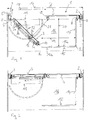
- Fig. 1 shows a passage device 1 with a frame 2 on which a passage door leaf 3 and a further door leaf 4 each with pivot bearings 5 pivotable are held.
- the passage door leaf 3 is according to the embodiment shown made up of several layers 3a and with vertical reinforcements 3b.
- the frame 2 comprises two vertical sections, which are in the assembled state extend essentially from floor to ceiling, and a horizontal one Connection that connects the two vertical sections at their top ends to each other are connected.
- the pivot bearings 5 are on the inside of the passage device arranged and allow opening of the door panels 3 and 4 against the Interior of a secured room 6.
- the frame 2 is connected to one of the two vertical Sections on pivot bearings 5 arranged on the outside 7 on one angle profile 8 mounted on the building side is pivotally attached.
- a fourth locking device preferably with an electromagnetic Holding device, provided.
- the fourth locking device is preferably unlocked when de-energized. In the event of a fire alarm, the fourth locking device unlocked so that the frame 2, as shown in Fig. 5, together with the two Door panels 3 and 4 can be pushed open, creating a large escape opening.
- the further door leaf 4 is in the closed state on the horizontal connection the frame 2 lockable with a first locking device 9.
- the passage door leaf 3, is in the closed state on the other door leaf 4 and / or on the horizontal connection of the frame 2 to a second locking device 10 lockable.
- For automatic opening and closing of the passage door leaf 3 To enable a door operating device 11 on the horizontal connection of the frame 2 arranged.
- the passage door leaf 3 is preferably actuated with a swivel arm 12 of the door operating device 11, which in a with the passage door leaf 3 connected rail 13 engages.
- the other door leaf 4 is in the area of the pivotable connection to the frame 2 a first partition 14 pivotally mounted with pivot bearings 5.
- a second partition 15 is pivotable about pivot bearing 5 connected to the first partition 14.
- the second partition 15 is preferred formed in two parts.
- a second partial wall 15b can be in a first partial wall 15a second partition 15 inserted and pulled out of this.
- the two partitions 14 and 15 together with the another door leaf 4 a separating cabin 16.
- To adjust the partitions To prevent 14 and 15, at least the second partition 15, in particular in the area the second partial wall 15b with a fastening device, not shown in FIG their position. If the second partition 15 is fixed, the first one is also Partition 14 no longer adjustable.
- the fastening device is so with the control device connected that the fixed and the free state of the separation cabin 16 can be detected by the control device. It goes without saying that the two partitions 14 and 15 could also be attached to the building.
- the second partial wall 15b inserted into the first partial wall 15a and then the second partition 15 can be pivoted to the first partition.
- the separation cabin 16 completely be eliminated. This provides access to the from the secured room release another door leaf 4.
- the second partition wall 15 swivel away to the side to give access to the further door leaf 4, or to be able to open it inwards. Without the separation cabin 16, the Passage door leaf 3 from the door operating device 11 to a second Opening angle of approx. 90 ° opened and then closed again.
- the separating cabin 16 is in the separating operation according to FIGS. 1 and 2 assigned to the free vertical edge of the passage door leaf 3.
- the first Partition 14 leads away from the plane of the frame 2 and the second partition 15 extends from this plane spaced substantially parallel to the other Door leaf 4 so far against the passage door leaf 3 that the distance between the second partition 15 and the open to the first opening angle Passage door leaf 3 is so small that the passage of people from the Separation cabin 16 is only possible when the passage wing 3 is closed so far is that no one enters the separation cabin from outside can.
- the dimensions must be chosen optimally. In a preferred embodiment, an entire installation width 17 or a wall dimension of 1550mm.
- the door width 18 of the passage door leaf 3 is at substantially 700mm, the separation width 19 at essentially 690mm and the separation depth 20 at essentially 570mm fixed. This results in the opening of the door leaf 3 to at the first opening angle an entry width 21 for entry into the separating cabin of essentially 465mm. This dimension enables isolation, without unnecessarily restricting the people passing through.
- FIGS. 6 and 7 show the passage device with partitions 14 folded away and 15.
- the passage door leaf 3 is recognizable as a door.
- a horizontal connection surface 22 is arranged on the building side which of the passage door leaves 3 at least in the first opening angle and / or at least the second, but possibly also the first, partition 14 or 15 of the Separation cabin 16 can be fixed.
- a circular recess is formed, which in FIGS. 1-5 is shown in dashed lines.
- control device for triggering Pass-through processes and preferably also a further control device for Setting the desired operating status arranged.
- These control devices are connected to the control device.
- the control device must record can determine whether the conditions required for the desired operating mode are fulfilled.
- the separation cabin must be used for the separation operation are available what can be detected by the control device.
- the other must also Door leaf must be locked.
- the control device detects during an isolated Passage also whether the passage door leaf is in position at the first opening angle is set by the third locking device. At the end of a pass must be determined whether the passage door leaf is locked again. If this is not the case within a predetermined time, then another pass prevented and preferably triggered an alarm.
- the control device is preferred also connected to a burglar alarm system, so that for example it can be guaranteed that the alarm system can only be switched on, when the passage device is in the separation operation. It goes without saying itself that the described passage device with all from the area of occasional passage known control, detection and monitoring devices can be equipped to achieve the desired security.
Landscapes
- Business, Economics & Management (AREA)
- Accounting & Taxation (AREA)
- Finance (AREA)
- Physics & Mathematics (AREA)
- General Physics & Mathematics (AREA)
- Power-Operated Mechanisms For Wings (AREA)
- Wing Frames And Configurations (AREA)
- Specific Sealing Or Ventilating Devices For Doors And Windows (AREA)
- Extensible Doors And Revolving Doors (AREA)
- Lock And Its Accessories (AREA)
- Finger-Pressure Massage (AREA)
- Electrical Discharge Machining, Electrochemical Machining, And Combined Machining (AREA)
- Control And Other Processes For Unpacking Of Materials (AREA)
Priority Applications (4)
| Application Number | Priority Date | Filing Date | Title |
|---|---|---|---|
| EP01129939A EP1189178B1 (fr) | 2000-04-06 | 2000-04-06 | Dispositif de passage |
| DE50015194T DE50015194D1 (de) | 2000-04-06 | 2000-04-06 | Durchtritts-Vorrichtung |
| AT01129939T ATE397773T1 (de) | 2000-04-06 | 2000-04-06 | Durchtritts-vorrichtung |
| EP00107452A EP1143386A1 (fr) | 2000-04-06 | 2000-04-06 | Dispositif de passage |
Applications Claiming Priority (1)
| Application Number | Priority Date | Filing Date | Title |
|---|---|---|---|
| EP00107452A EP1143386A1 (fr) | 2000-04-06 | 2000-04-06 | Dispositif de passage |
Related Child Applications (1)
| Application Number | Title | Priority Date | Filing Date |
|---|---|---|---|
| EP01129939A Division EP1189178B1 (fr) | 2000-04-06 | 2000-04-06 | Dispositif de passage |
Publications (1)
| Publication Number | Publication Date |
|---|---|
| EP1143386A1 true EP1143386A1 (fr) | 2001-10-10 |
Family
ID=8168390
Family Applications (2)
| Application Number | Title | Priority Date | Filing Date |
|---|---|---|---|
| EP00107452A Withdrawn EP1143386A1 (fr) | 2000-04-06 | 2000-04-06 | Dispositif de passage |
| EP01129939A Expired - Lifetime EP1189178B1 (fr) | 2000-04-06 | 2000-04-06 | Dispositif de passage |
Family Applications After (1)
| Application Number | Title | Priority Date | Filing Date |
|---|---|---|---|
| EP01129939A Expired - Lifetime EP1189178B1 (fr) | 2000-04-06 | 2000-04-06 | Dispositif de passage |
Country Status (3)
| Country | Link |
|---|---|
| EP (2) | EP1143386A1 (fr) |
| AT (1) | ATE397773T1 (fr) |
| DE (1) | DE50015194D1 (fr) |
Cited By (3)
| Publication number | Priority date | Publication date | Assignee | Title |
|---|---|---|---|---|
| CN113719218A (zh) * | 2021-08-05 | 2021-11-30 | 江西德沃箱柜制造有限公司 | 一种防爆警报防盗金库门 |
| CN114635617A (zh) * | 2022-03-30 | 2022-06-17 | 武汉诺得佳科技有限公司 | 一种用于无人零售超市的交互式智能机器人 |
| CN115273286A (zh) * | 2022-08-03 | 2022-11-01 | 杭州恒生数字设备科技有限公司 | 试卷箱的开锁方法、系统和试卷箱 |
Families Citing this family (1)
| Publication number | Priority date | Publication date | Assignee | Title |
|---|---|---|---|---|
| FR2943376B1 (fr) * | 2009-03-18 | 2013-03-22 | Gunnebo Electronic Security | Sas de securite. |
Citations (8)
| Publication number | Priority date | Publication date | Assignee | Title |
|---|---|---|---|---|
| US2076765A (en) * | 1933-03-25 | 1937-04-13 | Glen R Eldred | Protective device |
| FR83178E (fr) * | 1963-01-29 | 1964-06-26 | Blocage automatique des issues en cas d'agression | |
| EP0110819A2 (fr) * | 1982-09-29 | 1984-06-13 | Alex Huber | Dispositif pour séparer les personnes à l'entrée d'un domaine |
| US4947765A (en) | 1989-04-25 | 1990-08-14 | National Bulletproof, Inc. | Security apparatus and method of using same |
| FR2731462A1 (fr) * | 1995-03-07 | 1996-09-13 | Tech Et Securite | Porte a battant pivotant et sas equipe de cette porte |
| WO1997020290A1 (fr) | 1995-11-27 | 1997-06-05 | Alex Huber | Dispositif pour isoler des personnes |
| FR2773249A1 (fr) * | 1997-11-24 | 1999-07-02 | Huber Alex | Dispositif pour separer des personnes |
| WO1999055995A1 (fr) * | 1998-04-29 | 1999-11-04 | Malcolm William Thomas | Systeme de commande d'acces |
-
2000
- 2000-04-06 EP EP00107452A patent/EP1143386A1/fr not_active Withdrawn
- 2000-04-06 AT AT01129939T patent/ATE397773T1/de not_active IP Right Cessation
- 2000-04-06 DE DE50015194T patent/DE50015194D1/de not_active Expired - Lifetime
- 2000-04-06 EP EP01129939A patent/EP1189178B1/fr not_active Expired - Lifetime
Patent Citations (8)
| Publication number | Priority date | Publication date | Assignee | Title |
|---|---|---|---|---|
| US2076765A (en) * | 1933-03-25 | 1937-04-13 | Glen R Eldred | Protective device |
| FR83178E (fr) * | 1963-01-29 | 1964-06-26 | Blocage automatique des issues en cas d'agression | |
| EP0110819A2 (fr) * | 1982-09-29 | 1984-06-13 | Alex Huber | Dispositif pour séparer les personnes à l'entrée d'un domaine |
| US4947765A (en) | 1989-04-25 | 1990-08-14 | National Bulletproof, Inc. | Security apparatus and method of using same |
| FR2731462A1 (fr) * | 1995-03-07 | 1996-09-13 | Tech Et Securite | Porte a battant pivotant et sas equipe de cette porte |
| WO1997020290A1 (fr) | 1995-11-27 | 1997-06-05 | Alex Huber | Dispositif pour isoler des personnes |
| FR2773249A1 (fr) * | 1997-11-24 | 1999-07-02 | Huber Alex | Dispositif pour separer des personnes |
| WO1999055995A1 (fr) * | 1998-04-29 | 1999-11-04 | Malcolm William Thomas | Systeme de commande d'acces |
Cited By (5)
| Publication number | Priority date | Publication date | Assignee | Title |
|---|---|---|---|---|
| CN113719218A (zh) * | 2021-08-05 | 2021-11-30 | 江西德沃箱柜制造有限公司 | 一种防爆警报防盗金库门 |
| CN113719218B (zh) * | 2021-08-05 | 2023-03-28 | 江西德沃箱柜制造有限公司 | 一种防爆警报防盗金库门 |
| CN114635617A (zh) * | 2022-03-30 | 2022-06-17 | 武汉诺得佳科技有限公司 | 一种用于无人零售超市的交互式智能机器人 |
| CN114635617B (zh) * | 2022-03-30 | 2023-09-05 | 武汉诺得佳科技有限公司 | 一种用于无人零售超市的交互式智能机器人 |
| CN115273286A (zh) * | 2022-08-03 | 2022-11-01 | 杭州恒生数字设备科技有限公司 | 试卷箱的开锁方法、系统和试卷箱 |
Also Published As
| Publication number | Publication date |
|---|---|
| EP1189178A1 (fr) | 2002-03-20 |
| ATE397773T1 (de) | 2008-06-15 |
| EP1189178B1 (fr) | 2008-06-04 |
| DE50015194D1 (de) | 2008-07-17 |
Similar Documents
| Publication | Publication Date | Title |
|---|---|---|
| DE3001068A1 (de) | Sicherheitstuersystem | |
| EP2581334B1 (fr) | Protection contre les chutes pour les ascenseurs | |
| DE102017126765A1 (de) | Durchgangskontrollvorrichtung für Personen | |
| EP2058460B1 (fr) | Dispositif de verrouillage anti-effraction pour batiment | |
| DE202008000919U1 (de) | Schließanlage für eine einen Gangflügel und einen Standflügel aufweisende zweiflügelige Tür | |
| DE3738302A1 (de) | Fahrzeug fuer die personenbefoerderung | |
| CH647838A5 (de) | Vorrichtung zur vereinzelung von personen zwecks verhinderung des zutritts unbefugter in die dahinterliegenden raeume. | |
| EP1143386A1 (fr) | Dispositif de passage | |
| DE29619007U1 (de) | Verriegelungsvorrichtung | |
| WO2014086490A2 (fr) | Porte coulissante | |
| DE19917158C2 (de) | Mehrfachfunktions- und Sicherheitsrahmen für Fenster, Türen und sonstige bewegliche Flügel zum Verschließen von Öffnungen | |
| EP1496186A1 (fr) | Sas pour le controle du passage de personnes | |
| DE19705058A1 (de) | Vorrichtung zum Öffnen und Schließen von Fenstern eines Kraftfahrzeugs | |
| EP4042846B1 (fr) | Armoire de distribution comprenant un élément de fermeture précontraint dans une position d'ouverture | |
| DE10162793C2 (de) | Verriegelung für eine zweiflügelige Tür in Flucht- und Rettungswegen | |
| DE69904461T2 (de) | Zugangskontrollsystem | |
| DE3737151A1 (de) | Zweifluegelige tuer | |
| EP0902140A1 (fr) | Dispositif de porte avec verrouillage de porte | |
| EP4237649B1 (fr) | Fermeture dotée d'un dispositif de clapet | |
| EP1067270B1 (fr) | Dispositif de verrouillage pour un volet d'une ouverture de bâtiment, notamment pour un volet roulant | |
| EP0735221A2 (fr) | Dispositif de sécurité pour partie charnière de portes | |
| WO2012139682A1 (fr) | Système de vantail pouvant être actionné sans contact | |
| DE2328811A1 (de) | Tresorzelle fuer geldtransportfahrzeuge | |
| CH710152B1 (de) | Vorrichtung zum Vereinzeln von Personen. | |
| DE19735329A1 (de) | Dreh-Kippfenster oder -Tür |
Legal Events
| Date | Code | Title | Description |
|---|---|---|---|
| PUAI | Public reference made under article 153(3) epc to a published international application that has entered the european phase |
Free format text: ORIGINAL CODE: 0009012 |
|
| AK | Designated contracting states |
Kind code of ref document: A1 Designated state(s): AT BE CH CY DE DK ES FI FR GB GR IE IT LI LU MC NL PT SE |
|
| AX | Request for extension of the european patent |
Free format text: AL;LT;LV;MK;RO;SI |
|
| RAP1 | Party data changed (applicant data changed or rights of an application transferred) |
Owner name: SCHLIERENZAUER, KARL |
|
| AKX | Designation fees paid | ||
| REG | Reference to a national code |
Ref country code: DE Ref legal event code: 8566 |
|
| STAA | Information on the status of an ep patent application or granted ep patent |
Free format text: STATUS: THE APPLICATION IS DEEMED TO BE WITHDRAWN |
|
| 18D | Application deemed to be withdrawn |
Effective date: 20020411 |