EP1142835A2 - Tragbare Trinkwassergewinnungs- und Spendervorrichtung - Google Patents
Tragbare Trinkwassergewinnungs- und Spendervorrichtung Download PDFInfo
- Publication number
- EP1142835A2 EP1142835A2 EP20010201135 EP01201135A EP1142835A2 EP 1142835 A2 EP1142835 A2 EP 1142835A2 EP 20010201135 EP20010201135 EP 20010201135 EP 01201135 A EP01201135 A EP 01201135A EP 1142835 A2 EP1142835 A2 EP 1142835A2
- Authority
- EP
- European Patent Office
- Prior art keywords
- water
- condensate
- air
- reservoir
- liquid water
- Prior art date
- Legal status (The legal status is an assumption and is not a legal conclusion. Google has not performed a legal analysis and makes no representation as to the accuracy of the status listed.)
- Ceased
Links
- 239000003651 drinking water Substances 0.000 title claims abstract description 75
- 235000012206 bottled water Nutrition 0.000 title claims abstract description 68
- 238000011084 recovery Methods 0.000 title claims abstract description 6
- XLYOFNOQVPJJNP-UHFFFAOYSA-N water Substances O XLYOFNOQVPJJNP-UHFFFAOYSA-N 0.000 claims abstract description 646
- 239000003570 air Substances 0.000 claims abstract description 97
- 238000003860 storage Methods 0.000 claims abstract description 61
- 238000001816 cooling Methods 0.000 claims abstract description 54
- 239000007788 liquid Substances 0.000 claims abstract description 45
- OKTJSMMVPCPJKN-UHFFFAOYSA-N Carbon Chemical compound [C] OKTJSMMVPCPJKN-UHFFFAOYSA-N 0.000 claims abstract description 31
- 239000006096 absorbing agent Substances 0.000 claims abstract description 28
- 241000894006 Bacteria Species 0.000 claims abstract description 23
- 239000012080 ambient air Substances 0.000 claims abstract description 13
- 238000011282 treatment Methods 0.000 claims abstract description 13
- 230000005484 gravity Effects 0.000 claims abstract description 12
- 230000005855 radiation Effects 0.000 claims abstract description 12
- 241000700605 Viruses Species 0.000 claims abstract description 5
- 239000012530 fluid Substances 0.000 claims description 75
- 238000004519 manufacturing process Methods 0.000 claims description 32
- 238000007710 freezing Methods 0.000 claims description 19
- 230000008014 freezing Effects 0.000 claims description 19
- 230000006870 function Effects 0.000 claims description 19
- 235000020188 drinking water Nutrition 0.000 claims description 18
- 239000000463 material Substances 0.000 claims description 13
- 238000012360 testing method Methods 0.000 claims description 11
- 238000010257 thawing Methods 0.000 claims description 9
- 239000008213 purified water Substances 0.000 claims description 8
- 238000001914 filtration Methods 0.000 claims description 7
- 230000004224 protection Effects 0.000 claims description 7
- 230000003134 recirculating effect Effects 0.000 claims description 5
- 238000001514 detection method Methods 0.000 claims description 4
- 238000012544 monitoring process Methods 0.000 claims description 4
- 239000013618 particulate matter Substances 0.000 claims description 4
- 238000011144 upstream manufacturing Methods 0.000 claims description 4
- 230000001186 cumulative effect Effects 0.000 claims description 3
- 238000012163 sequencing technique Methods 0.000 claims description 3
- 238000009833 condensation Methods 0.000 abstract description 9
- 230000005494 condensation Effects 0.000 abstract description 8
- 239000012855 volatile organic compound Substances 0.000 description 31
- 239000000523 sample Substances 0.000 description 28
- 238000000034 method Methods 0.000 description 22
- 230000002147 killing effect Effects 0.000 description 21
- 239000002245 particle Substances 0.000 description 19
- 238000010438 heat treatment Methods 0.000 description 18
- 239000003507 refrigerant Substances 0.000 description 16
- 238000013461 design Methods 0.000 description 15
- 230000007613 environmental effect Effects 0.000 description 15
- 241000238631 Hexapoda Species 0.000 description 14
- CBENFWSGALASAD-UHFFFAOYSA-N Ozone Chemical compound [O-][O+]=O CBENFWSGALASAD-UHFFFAOYSA-N 0.000 description 14
- 239000000356 contaminant Substances 0.000 description 14
- 239000007789 gas Substances 0.000 description 14
- 239000012535 impurity Substances 0.000 description 10
- 241000607479 Yersinia pestis Species 0.000 description 9
- 238000013459 approach Methods 0.000 description 9
- 238000004140 cleaning Methods 0.000 description 9
- 238000002955 isolation Methods 0.000 description 9
- 238000005303 weighing Methods 0.000 description 9
- 238000012986 modification Methods 0.000 description 8
- 239000010935 stainless steel Substances 0.000 description 8
- 229910001220 stainless steel Inorganic materials 0.000 description 8
- 230000001954 sterilising effect Effects 0.000 description 8
- 239000000126 substance Substances 0.000 description 8
- 238000010586 diagram Methods 0.000 description 7
- 238000009428 plumbing Methods 0.000 description 7
- 229910045601 alloy Inorganic materials 0.000 description 6
- 239000000956 alloy Substances 0.000 description 6
- 150000002500 ions Chemical class 0.000 description 6
- 238000012423 maintenance Methods 0.000 description 6
- 230000004048 modification Effects 0.000 description 6
- 229920000642 polymer Polymers 0.000 description 6
- 230000008569 process Effects 0.000 description 6
- 238000000746 purification Methods 0.000 description 6
- 238000004659 sterilization and disinfection Methods 0.000 description 6
- 238000000576 coating method Methods 0.000 description 5
- 239000000428 dust Substances 0.000 description 5
- 230000002070 germicidal effect Effects 0.000 description 5
- 238000005192 partition Methods 0.000 description 5
- 230000000737 periodic effect Effects 0.000 description 5
- 238000005057 refrigeration Methods 0.000 description 5
- 230000003213 activating effect Effects 0.000 description 4
- 238000004378 air conditioning Methods 0.000 description 4
- 230000003466 anti-cipated effect Effects 0.000 description 4
- 238000003491 array Methods 0.000 description 4
- 230000001580 bacterial effect Effects 0.000 description 4
- 229910052799 carbon Inorganic materials 0.000 description 4
- 239000000919 ceramic Substances 0.000 description 4
- 230000008859 change Effects 0.000 description 4
- 239000011248 coating agent Substances 0.000 description 4
- 238000010276 construction Methods 0.000 description 4
- 230000035622 drinking Effects 0.000 description 4
- 239000011521 glass Substances 0.000 description 4
- 230000033001 locomotion Effects 0.000 description 4
- 229910052751 metal Inorganic materials 0.000 description 4
- 239000002184 metal Substances 0.000 description 4
- 239000007787 solid Substances 0.000 description 4
- 238000012546 transfer Methods 0.000 description 4
- 230000000007 visual effect Effects 0.000 description 4
- 239000000654 additive Substances 0.000 description 3
- 239000003463 adsorbent Substances 0.000 description 3
- 230000008901 benefit Effects 0.000 description 3
- 238000006243 chemical reaction Methods 0.000 description 3
- 238000004590 computer program Methods 0.000 description 3
- 230000008878 coupling Effects 0.000 description 3
- 238000010168 coupling process Methods 0.000 description 3
- 238000005859 coupling reaction Methods 0.000 description 3
- 239000003814 drug Substances 0.000 description 3
- 229920001971 elastomer Polymers 0.000 description 3
- 238000005265 energy consumption Methods 0.000 description 3
- 235000013305 food Nutrition 0.000 description 3
- 229910001385 heavy metal Inorganic materials 0.000 description 3
- 230000006872 improvement Effects 0.000 description 3
- 238000009413 insulation Methods 0.000 description 3
- 150000002739 metals Chemical class 0.000 description 3
- 231100000252 nontoxic Toxicity 0.000 description 3
- 230000003000 nontoxic effect Effects 0.000 description 3
- 239000004033 plastic Substances 0.000 description 3
- 229920003023 plastic Polymers 0.000 description 3
- 230000008439 repair process Effects 0.000 description 3
- 230000004044 response Effects 0.000 description 3
- 238000007789 sealing Methods 0.000 description 3
- 238000000926 separation method Methods 0.000 description 3
- 230000008093 supporting effect Effects 0.000 description 3
- 231100000331 toxic Toxicity 0.000 description 3
- 230000002588 toxic effect Effects 0.000 description 3
- ZAMOUSCENKQFHK-UHFFFAOYSA-N Chlorine atom Chemical compound [Cl] ZAMOUSCENKQFHK-UHFFFAOYSA-N 0.000 description 2
- 241000195493 Cryptophyta Species 0.000 description 2
- 241000255925 Diptera Species 0.000 description 2
- MHAJPDPJQMAIIY-UHFFFAOYSA-N Hydrogen peroxide Chemical compound OO MHAJPDPJQMAIIY-UHFFFAOYSA-N 0.000 description 2
- 206010061217 Infestation Diseases 0.000 description 2
- 230000004913 activation Effects 0.000 description 2
- 239000000443 aerosol Substances 0.000 description 2
- 230000004888 barrier function Effects 0.000 description 2
- 230000015572 biosynthetic process Effects 0.000 description 2
- 238000009835 boiling Methods 0.000 description 2
- 239000006227 byproduct Substances 0.000 description 2
- 239000003610 charcoal Substances 0.000 description 2
- 238000007600 charging Methods 0.000 description 2
- 229910052801 chlorine Inorganic materials 0.000 description 2
- 239000000460 chlorine Substances 0.000 description 2
- 239000011538 cleaning material Substances 0.000 description 2
- 239000003086 colorant Substances 0.000 description 2
- 238000004891 communication Methods 0.000 description 2
- 239000002131 composite material Substances 0.000 description 2
- 238000007906 compression Methods 0.000 description 2
- 238000011109 contamination Methods 0.000 description 2
- 230000007123 defense Effects 0.000 description 2
- 239000002384 drinking water standard Substances 0.000 description 2
- 229940079593 drug Drugs 0.000 description 2
- 230000000694 effects Effects 0.000 description 2
- 239000000806 elastomer Substances 0.000 description 2
- 230000005611 electricity Effects 0.000 description 2
- 238000011049 filling Methods 0.000 description 2
- -1 flavoring Substances 0.000 description 2
- 239000006260 foam Substances 0.000 description 2
- 239000011888 foil Substances 0.000 description 2
- 230000036541 health Effects 0.000 description 2
- 239000005457 ice water Substances 0.000 description 2
- 238000007654 immersion Methods 0.000 description 2
- 230000001976 improved effect Effects 0.000 description 2
- 239000011810 insulating material Substances 0.000 description 2
- NOESYZHRGYRDHS-UHFFFAOYSA-N insulin Chemical compound N1C(=O)C(NC(=O)C(CCC(N)=O)NC(=O)C(CCC(O)=O)NC(=O)C(C(C)C)NC(=O)C(NC(=O)CN)C(C)CC)CSSCC(C(NC(CO)C(=O)NC(CC(C)C)C(=O)NC(CC=2C=CC(O)=CC=2)C(=O)NC(CCC(N)=O)C(=O)NC(CC(C)C)C(=O)NC(CCC(O)=O)C(=O)NC(CC(N)=O)C(=O)NC(CC=2C=CC(O)=CC=2)C(=O)NC(CSSCC(NC(=O)C(C(C)C)NC(=O)C(CC(C)C)NC(=O)C(CC=2C=CC(O)=CC=2)NC(=O)C(CC(C)C)NC(=O)C(C)NC(=O)C(CCC(O)=O)NC(=O)C(C(C)C)NC(=O)C(CC(C)C)NC(=O)C(CC=2NC=NC=2)NC(=O)C(CO)NC(=O)CNC2=O)C(=O)NCC(=O)NC(CCC(O)=O)C(=O)NC(CCCNC(N)=N)C(=O)NCC(=O)NC(CC=3C=CC=CC=3)C(=O)NC(CC=3C=CC=CC=3)C(=O)NC(CC=3C=CC(O)=CC=3)C(=O)NC(C(C)O)C(=O)N3C(CCC3)C(=O)NC(CCCCN)C(=O)NC(C)C(O)=O)C(=O)NC(CC(N)=O)C(O)=O)=O)NC(=O)C(C(C)CC)NC(=O)C(CO)NC(=O)C(C(C)O)NC(=O)C1CSSCC2NC(=O)C(CC(C)C)NC(=O)C(NC(=O)C(CCC(N)=O)NC(=O)C(CC(N)=O)NC(=O)C(NC(=O)C(N)CC=1C=CC=CC=1)C(C)C)CC1=CN=CN1 NOESYZHRGYRDHS-UHFFFAOYSA-N 0.000 description 2
- 230000007774 longterm Effects 0.000 description 2
- 230000014759 maintenance of location Effects 0.000 description 2
- 239000000155 melt Substances 0.000 description 2
- 239000012528 membrane Substances 0.000 description 2
- 244000005700 microbiome Species 0.000 description 2
- 229940029985 mineral supplement Drugs 0.000 description 2
- 235000020786 mineral supplement Nutrition 0.000 description 2
- 239000000203 mixture Substances 0.000 description 2
- 239000000575 pesticide Substances 0.000 description 2
- 229910052699 polonium Inorganic materials 0.000 description 2
- HZEBHPIOVYHPMT-UHFFFAOYSA-N polonium atom Chemical compound [Po] HZEBHPIOVYHPMT-UHFFFAOYSA-N 0.000 description 2
- 239000002861 polymer material Substances 0.000 description 2
- 239000011148 porous material Substances 0.000 description 2
- 238000002360 preparation method Methods 0.000 description 2
- 230000037452 priming Effects 0.000 description 2
- 230000001681 protective effect Effects 0.000 description 2
- 238000005086 pumping Methods 0.000 description 2
- 238000005067 remediation Methods 0.000 description 2
- 238000010079 rubber tapping Methods 0.000 description 2
- 238000011012 sanitization Methods 0.000 description 2
- 239000000565 sealant Substances 0.000 description 2
- 238000000638 solvent extraction Methods 0.000 description 2
- 238000001179 sorption measurement Methods 0.000 description 2
- 238000005507 spraying Methods 0.000 description 2
- 230000009182 swimming Effects 0.000 description 2
- 239000008399 tap water Substances 0.000 description 2
- 235000020679 tap water Nutrition 0.000 description 2
- 230000001960 triggered effect Effects 0.000 description 2
- 239000011782 vitamin Substances 0.000 description 2
- 229940088594 vitamin Drugs 0.000 description 2
- 229930003231 vitamin Natural products 0.000 description 2
- 235000013343 vitamin Nutrition 0.000 description 2
- 239000002351 wastewater Substances 0.000 description 2
- 241000223935 Cryptosporidium Species 0.000 description 1
- 241000588724 Escherichia coli Species 0.000 description 1
- JOYRKODLDBILNP-UHFFFAOYSA-N Ethyl urethane Chemical compound CCOC(N)=O JOYRKODLDBILNP-UHFFFAOYSA-N 0.000 description 1
- PXGOKWXKJXAPGV-UHFFFAOYSA-N Fluorine Chemical compound FF PXGOKWXKJXAPGV-UHFFFAOYSA-N 0.000 description 1
- 206010019233 Headaches Diseases 0.000 description 1
- 102000004877 Insulin Human genes 0.000 description 1
- 108090001061 Insulin Proteins 0.000 description 1
- 102220565243 L-lactate dehydrogenase A-like 6A_M11A_mutation Human genes 0.000 description 1
- 241001544487 Macromiidae Species 0.000 description 1
- 230000005679 Peltier effect Effects 0.000 description 1
- 208000015634 Rectal Neoplasms Diseases 0.000 description 1
- 241000283984 Rodentia Species 0.000 description 1
- 208000007097 Urinary Bladder Neoplasms Diseases 0.000 description 1
- 208000034817 Waterborne disease Diseases 0.000 description 1
- 238000010521 absorption reaction Methods 0.000 description 1
- 229920006397 acrylic thermoplastic Polymers 0.000 description 1
- 230000009471 action Effects 0.000 description 1
- 230000001154 acute effect Effects 0.000 description 1
- 230000000996 additive effect Effects 0.000 description 1
- 150000001336 alkenes Chemical class 0.000 description 1
- 150000001408 amides Chemical class 0.000 description 1
- 150000001450 anions Chemical class 0.000 description 1
- 230000000844 anti-bacterial effect Effects 0.000 description 1
- QVGXLLKOCUKJST-UHFFFAOYSA-N atomic oxygen Chemical compound [O] QVGXLLKOCUKJST-UHFFFAOYSA-N 0.000 description 1
- 239000003899 bactericide agent Substances 0.000 description 1
- 235000013361 beverage Nutrition 0.000 description 1
- 230000004071 biological effect Effects 0.000 description 1
- 230000033228 biological regulation Effects 0.000 description 1
- 230000005540 biological transmission Effects 0.000 description 1
- 238000007664 blowing Methods 0.000 description 1
- 231100000357 carcinogen Toxicity 0.000 description 1
- 239000003183 carcinogenic agent Substances 0.000 description 1
- 230000015556 catabolic process Effects 0.000 description 1
- 239000003054 catalyst Substances 0.000 description 1
- 150000001768 cations Chemical class 0.000 description 1
- 238000001311 chemical methods and process Methods 0.000 description 1
- 239000013626 chemical specie Substances 0.000 description 1
- 239000003795 chemical substances by application Substances 0.000 description 1
- 238000005660 chlorination reaction Methods 0.000 description 1
- 239000000084 colloidal system Substances 0.000 description 1
- 150000001875 compounds Chemical class 0.000 description 1
- 230000006835 compression Effects 0.000 description 1
- 230000003750 conditioning effect Effects 0.000 description 1
- 239000004020 conductor Substances 0.000 description 1
- 230000001276 controlling effect Effects 0.000 description 1
- 239000010949 copper Substances 0.000 description 1
- 230000009193 crawling Effects 0.000 description 1
- 239000013078 crystal Substances 0.000 description 1
- 208000031513 cyst Diseases 0.000 description 1
- 230000003247 decreasing effect Effects 0.000 description 1
- 230000007812 deficiency Effects 0.000 description 1
- 238000006731 degradation reaction Methods 0.000 description 1
- 230000001419 dependent effect Effects 0.000 description 1
- 230000000994 depressogenic effect Effects 0.000 description 1
- 230000000249 desinfective effect Effects 0.000 description 1
- 238000007598 dipping method Methods 0.000 description 1
- KPUWHANPEXNPJT-UHFFFAOYSA-N disiloxane Chemical class [SiH3]O[SiH3] KPUWHANPEXNPJT-UHFFFAOYSA-N 0.000 description 1
- 230000005670 electromagnetic radiation Effects 0.000 description 1
- 238000007786 electrostatic charging Methods 0.000 description 1
- 238000009503 electrostatic coating Methods 0.000 description 1
- 238000005516 engineering process Methods 0.000 description 1
- 239000003344 environmental pollutant Substances 0.000 description 1
- 238000001704 evaporation Methods 0.000 description 1
- 230000002349 favourable effect Effects 0.000 description 1
- 239000007888 film coating Substances 0.000 description 1
- 238000009501 film coating Methods 0.000 description 1
- 238000007667 floating Methods 0.000 description 1
- 229910052731 fluorine Inorganic materials 0.000 description 1
- 239000011737 fluorine Substances 0.000 description 1
- 230000004907 flux Effects 0.000 description 1
- 239000008187 granular material Substances 0.000 description 1
- 239000004519 grease Substances 0.000 description 1
- 229910052736 halogen Inorganic materials 0.000 description 1
- 150000002367 halogens Chemical class 0.000 description 1
- 239000000383 hazardous chemical Substances 0.000 description 1
- 231100000206 health hazard Toxicity 0.000 description 1
- 239000012676 herbal extract Substances 0.000 description 1
- 229930195733 hydrocarbon Natural products 0.000 description 1
- 150000002430 hydrocarbons Chemical class 0.000 description 1
- 230000002209 hydrophobic effect Effects 0.000 description 1
- 238000005286 illumination Methods 0.000 description 1
- 238000010348 incorporation Methods 0.000 description 1
- 239000002440 industrial waste Substances 0.000 description 1
- 230000000977 initiatory effect Effects 0.000 description 1
- 238000002347 injection Methods 0.000 description 1
- 239000007924 injection Substances 0.000 description 1
- 238000003780 insertion Methods 0.000 description 1
- 230000037431 insertion Effects 0.000 description 1
- 238000009434 installation Methods 0.000 description 1
- 239000012774 insulation material Substances 0.000 description 1
- 229940125396 insulin Drugs 0.000 description 1
- 230000003993 interaction Effects 0.000 description 1
- 239000002648 laminated material Substances 0.000 description 1
- 239000006193 liquid solution Substances 0.000 description 1
- 238000007726 management method Methods 0.000 description 1
- 230000013011 mating Effects 0.000 description 1
- 238000005259 measurement Methods 0.000 description 1
- 230000007246 mechanism Effects 0.000 description 1
- 239000004745 nonwoven fabric Substances 0.000 description 1
- JRZJOMJEPLMPRA-UHFFFAOYSA-N olefin Natural products CCCCCCCC=C JRZJOMJEPLMPRA-UHFFFAOYSA-N 0.000 description 1
- 230000003287 optical effect Effects 0.000 description 1
- 150000002896 organic halogen compounds Chemical class 0.000 description 1
- 239000011368 organic material Substances 0.000 description 1
- 230000001590 oxidative effect Effects 0.000 description 1
- 229910052760 oxygen Inorganic materials 0.000 description 1
- 239000001301 oxygen Substances 0.000 description 1
- 244000045947 parasite Species 0.000 description 1
- 230000036961 partial effect Effects 0.000 description 1
- 230000037361 pathway Effects 0.000 description 1
- 230000035515 penetration Effects 0.000 description 1
- 235000021178 picnic Nutrition 0.000 description 1
- 231100000719 pollutant Toxicity 0.000 description 1
- 229920003229 poly(methyl methacrylate) Polymers 0.000 description 1
- 239000004417 polycarbonate Substances 0.000 description 1
- 229920000515 polycarbonate Polymers 0.000 description 1
- 229920000098 polyolefin Polymers 0.000 description 1
- 239000004810 polytetrafluoroethylene Substances 0.000 description 1
- 229920001343 polytetrafluoroethylene Polymers 0.000 description 1
- 238000002203 pretreatment Methods 0.000 description 1
- 230000000750 progressive effect Effects 0.000 description 1
- 230000002035 prolonged effect Effects 0.000 description 1
- 230000005180 public health Effects 0.000 description 1
- 239000010453 quartz Substances 0.000 description 1
- 230000002285 radioactive effect Effects 0.000 description 1
- 229910052705 radium Inorganic materials 0.000 description 1
- HCWPIIXVSYCSAN-UHFFFAOYSA-N radium atom Chemical compound [Ra] HCWPIIXVSYCSAN-UHFFFAOYSA-N 0.000 description 1
- 230000009467 reduction Effects 0.000 description 1
- 230000002829 reductive effect Effects 0.000 description 1
- 238000002310 reflectometry Methods 0.000 description 1
- 230000001105 regulatory effect Effects 0.000 description 1
- 230000000284 resting effect Effects 0.000 description 1
- 230000002441 reversible effect Effects 0.000 description 1
- 238000005096 rolling process Methods 0.000 description 1
- 238000005201 scrubbing Methods 0.000 description 1
- 230000035945 sensitivity Effects 0.000 description 1
- 230000011664 signaling Effects 0.000 description 1
- VYPSYNLAJGMNEJ-UHFFFAOYSA-N silicon dioxide Inorganic materials O=[Si]=O VYPSYNLAJGMNEJ-UHFFFAOYSA-N 0.000 description 1
- 238000004513 sizing Methods 0.000 description 1
- 239000008400 supply water Substances 0.000 description 1
- ISXSCDLOGDJUNJ-UHFFFAOYSA-N tert-butyl prop-2-enoate Chemical compound CC(C)(C)OC(=O)C=C ISXSCDLOGDJUNJ-UHFFFAOYSA-N 0.000 description 1
- 230000001225 therapeutic effect Effects 0.000 description 1
- 239000002699 waste material Substances 0.000 description 1
- 235000020681 well water Nutrition 0.000 description 1
- 239000002349 well water Substances 0.000 description 1
Images


Classifications
-
- B—PERFORMING OPERATIONS; TRANSPORTING
- B01—PHYSICAL OR CHEMICAL PROCESSES OR APPARATUS IN GENERAL
- B01D—SEPARATION
- B01D5/00—Condensation of vapours; Recovering volatile solvents by condensation
- B01D5/0057—Condensation of vapours; Recovering volatile solvents by condensation in combination with other processes
- B01D5/0072—Condensation of vapours; Recovering volatile solvents by condensation in combination with other processes with filtration
-
- C—CHEMISTRY; METALLURGY
- C02—TREATMENT OF WATER, WASTE WATER, SEWAGE, OR SLUDGE
- C02F—TREATMENT OF WATER, WASTE WATER, SEWAGE, OR SLUDGE
- C02F1/00—Treatment of water, waste water, or sewage
- C02F1/008—Control or steering systems not provided for elsewhere in subclass C02F
-
- C—CHEMISTRY; METALLURGY
- C02—TREATMENT OF WATER, WASTE WATER, SEWAGE, OR SLUDGE
- C02F—TREATMENT OF WATER, WASTE WATER, SEWAGE, OR SLUDGE
- C02F9/00—Multistage treatment of water, waste water or sewage
- C02F9/20—Portable or detachable small-scale multistage treatment devices, e.g. point of use or laboratory water purification systems
-
- E—FIXED CONSTRUCTIONS
- E03—WATER SUPPLY; SEWERAGE
- E03B—INSTALLATIONS OR METHODS FOR OBTAINING, COLLECTING, OR DISTRIBUTING WATER
- E03B3/00—Methods or installations for obtaining or collecting drinking water or tap water
- E03B3/28—Methods or installations for obtaining or collecting drinking water or tap water from humid air
-
- B—PERFORMING OPERATIONS; TRANSPORTING
- B67—OPENING, CLOSING OR CLEANING BOTTLES, JARS OR SIMILAR CONTAINERS; LIQUID HANDLING
- B67D—DISPENSING, DELIVERING OR TRANSFERRING LIQUIDS, NOT OTHERWISE PROVIDED FOR
- B67D2210/00—Indexing scheme relating to aspects and details of apparatus or devices for dispensing beverages on draught or for controlling flow of liquids under gravity from storage containers for dispensing purposes
- B67D2210/00002—Purifying means
- B67D2210/00013—Sterilising means
- B67D2210/00015—UV radiation
-
- C—CHEMISTRY; METALLURGY
- C02—TREATMENT OF WATER, WASTE WATER, SEWAGE, OR SLUDGE
- C02F—TREATMENT OF WATER, WASTE WATER, SEWAGE, OR SLUDGE
- C02F1/00—Treatment of water, waste water, or sewage
- C02F1/001—Processes for the treatment of water whereby the filtration technique is of importance
-
- C—CHEMISTRY; METALLURGY
- C02—TREATMENT OF WATER, WASTE WATER, SEWAGE, OR SLUDGE
- C02F—TREATMENT OF WATER, WASTE WATER, SEWAGE, OR SLUDGE
- C02F1/00—Treatment of water, waste water, or sewage
- C02F1/28—Treatment of water, waste water, or sewage by sorption
- C02F1/283—Treatment of water, waste water, or sewage by sorption using coal, charred products, or inorganic mixtures containing them
-
- C—CHEMISTRY; METALLURGY
- C02—TREATMENT OF WATER, WASTE WATER, SEWAGE, OR SLUDGE
- C02F—TREATMENT OF WATER, WASTE WATER, SEWAGE, OR SLUDGE
- C02F1/00—Treatment of water, waste water, or sewage
- C02F1/30—Treatment of water, waste water, or sewage by irradiation
- C02F1/32—Treatment of water, waste water, or sewage by irradiation with ultraviolet light
-
- C—CHEMISTRY; METALLURGY
- C02—TREATMENT OF WATER, WASTE WATER, SEWAGE, OR SLUDGE
- C02F—TREATMENT OF WATER, WASTE WATER, SEWAGE, OR SLUDGE
- C02F1/00—Treatment of water, waste water, or sewage
- C02F1/34—Treatment of water, waste water, or sewage with mechanical oscillations
- C02F1/36—Treatment of water, waste water, or sewage with mechanical oscillations ultrasonic vibrations
-
- C—CHEMISTRY; METALLURGY
- C02—TREATMENT OF WATER, WASTE WATER, SEWAGE, OR SLUDGE
- C02F—TREATMENT OF WATER, WASTE WATER, SEWAGE, OR SLUDGE
- C02F2201/00—Apparatus for treatment of water, waste water or sewage
- C02F2201/009—Apparatus with independent power supply, e.g. solar cells, windpower or fuel cells
-
- C—CHEMISTRY; METALLURGY
- C02—TREATMENT OF WATER, WASTE WATER, SEWAGE, OR SLUDGE
- C02F—TREATMENT OF WATER, WASTE WATER, SEWAGE, OR SLUDGE
- C02F2209/00—Controlling or monitoring parameters in water treatment
- C02F2209/005—Processes using a programmable logic controller [PLC]
- C02F2209/008—Processes using a programmable logic controller [PLC] comprising telecommunication features, e.g. modems or antennas
-
- C—CHEMISTRY; METALLURGY
- C02—TREATMENT OF WATER, WASTE WATER, SEWAGE, OR SLUDGE
- C02F—TREATMENT OF WATER, WASTE WATER, SEWAGE, OR SLUDGE
- C02F2209/00—Controlling or monitoring parameters in water treatment
- C02F2209/02—Temperature
-
- C—CHEMISTRY; METALLURGY
- C02—TREATMENT OF WATER, WASTE WATER, SEWAGE, OR SLUDGE
- C02F—TREATMENT OF WATER, WASTE WATER, SEWAGE, OR SLUDGE
- C02F2209/00—Controlling or monitoring parameters in water treatment
- C02F2209/40—Liquid flow rate
-
- C—CHEMISTRY; METALLURGY
- C02—TREATMENT OF WATER, WASTE WATER, SEWAGE, OR SLUDGE
- C02F—TREATMENT OF WATER, WASTE WATER, SEWAGE, OR SLUDGE
- C02F2209/00—Controlling or monitoring parameters in water treatment
- C02F2209/42—Liquid level
-
- C—CHEMISTRY; METALLURGY
- C02—TREATMENT OF WATER, WASTE WATER, SEWAGE, OR SLUDGE
- C02F—TREATMENT OF WATER, WASTE WATER, SEWAGE, OR SLUDGE
- C02F9/00—Multistage treatment of water, waste water or sewage
-
- Y—GENERAL TAGGING OF NEW TECHNOLOGICAL DEVELOPMENTS; GENERAL TAGGING OF CROSS-SECTIONAL TECHNOLOGIES SPANNING OVER SEVERAL SECTIONS OF THE IPC; TECHNICAL SUBJECTS COVERED BY FORMER USPC CROSS-REFERENCE ART COLLECTIONS [XRACs] AND DIGESTS
- Y02—TECHNOLOGIES OR APPLICATIONS FOR MITIGATION OR ADAPTATION AGAINST CLIMATE CHANGE
- Y02A—TECHNOLOGIES FOR ADAPTATION TO CLIMATE CHANGE
- Y02A20/00—Water conservation; Efficient water supply; Efficient water use
- Y02A20/20—Controlling water pollution; Waste water treatment
- Y02A20/208—Off-grid powered water treatment
- Y02A20/211—Solar-powered water purification
-
- Y—GENERAL TAGGING OF NEW TECHNOLOGICAL DEVELOPMENTS; GENERAL TAGGING OF CROSS-SECTIONAL TECHNOLOGIES SPANNING OVER SEVERAL SECTIONS OF THE IPC; TECHNICAL SUBJECTS COVERED BY FORMER USPC CROSS-REFERENCE ART COLLECTIONS [XRACs] AND DIGESTS
- Y02—TECHNOLOGIES OR APPLICATIONS FOR MITIGATION OR ADAPTATION AGAINST CLIMATE CHANGE
- Y02A—TECHNOLOGIES FOR ADAPTATION TO CLIMATE CHANGE
- Y02A20/00—Water conservation; Efficient water supply; Efficient water use
- Y02A20/20—Controlling water pollution; Waste water treatment
- Y02A20/208—Off-grid powered water treatment
- Y02A20/212—Solar-powered wastewater sewage treatment, e.g. spray evaporation
-
- Y—GENERAL TAGGING OF NEW TECHNOLOGICAL DEVELOPMENTS; GENERAL TAGGING OF CROSS-SECTIONAL TECHNOLOGIES SPANNING OVER SEVERAL SECTIONS OF THE IPC; TECHNICAL SUBJECTS COVERED BY FORMER USPC CROSS-REFERENCE ART COLLECTIONS [XRACs] AND DIGESTS
- Y02—TECHNOLOGIES OR APPLICATIONS FOR MITIGATION OR ADAPTATION AGAINST CLIMATE CHANGE
- Y02A—TECHNOLOGIES FOR ADAPTATION TO CLIMATE CHANGE
- Y02A50/00—TECHNOLOGIES FOR ADAPTATION TO CLIMATE CHANGE in human health protection, e.g. against extreme weather
- Y02A50/20—Air quality improvement or preservation, e.g. vehicle emission control or emission reduction by using catalytic converters
-
- Y—GENERAL TAGGING OF NEW TECHNOLOGICAL DEVELOPMENTS; GENERAL TAGGING OF CROSS-SECTIONAL TECHNOLOGIES SPANNING OVER SEVERAL SECTIONS OF THE IPC; TECHNICAL SUBJECTS COVERED BY FORMER USPC CROSS-REFERENCE ART COLLECTIONS [XRACs] AND DIGESTS
- Y02—TECHNOLOGIES OR APPLICATIONS FOR MITIGATION OR ADAPTATION AGAINST CLIMATE CHANGE
- Y02W—CLIMATE CHANGE MITIGATION TECHNOLOGIES RELATED TO WASTEWATER TREATMENT OR WASTE MANAGEMENT
- Y02W10/00—Technologies for wastewater treatment
- Y02W10/30—Wastewater or sewage treatment systems using renewable energies
- Y02W10/37—Wastewater or sewage treatment systems using renewable energies using solar energy
Definitions
- This invention relates to a portable, potable water dispenser capable of recovering liquid water for human use from the humidity of environmental air and sanitizing it for human use.
- the water generator of this invention draws in moisture-laden air from the surroundings and recovers liquid water by cooling the stream of air below its dew point.
- the unit can be powered from mains, single/3-phase, or portable generators, AC, 110-220 V, 50-60 Hz, DC power 60 V batteries or solar charged batteries.
- the apparatus includes optional air filters of various types which remove suspended pollen or dust particles so that contaminants and undesirable impurities from the environmental air are not carried into the dew-forming section.
- the apparatus also includes optional heating cooling devices and ionizing sub-systems.
- the most important feature of the basic unit and its variants are filtration and sterilization systems which provide purified liquid water free from contaminants and volatile organic compounds (VOC) as defined by NSF Standard 53.
- the external envelope of the present apparatus may be a compact, attractive furniture-type wheeled design, one embodiment of which is further adapted to prevent or discourage entry of insects.
- the water generators of this invention employ ruggedized design and construction and certain embodiments are intended to operate untended for extended periods in harsh, military-type environments such as peacekeeping actions, fires, earthquakes and weather disasters/ emergencies.
- Emergency-use embodiments are prepared with a feed valve manifold connected to an input port; this permits selected or additional inputs of water from any source, such as a swimming pool, in emergency conditions such as a natural disaster.
- Other embodiments are intended to operate in land-transport vehicles, e.g., off-road, bus, train, seagoing vessels, recreational vehicles, business or home office environments.
- Another embodiment includes an automated pressurized valve manifold, equipped with sensors to detect the amount of water being generated, connected to a pressurized municipal water supply to provide for admission of municipal water into the recirculating-purification system; this sub-system would be activated under atmospheric conditions which limit the generation of water from the environmental air.
- the manifold is pressurized either by the municipal water system or by an internal pump allowing for immediate dispensing of purified water at a drinking fountain or into a refrigerator's ice maker/chiller with or without electricity.
- Such embodiments include an electronic control, specifically a microprocessor, to sense critical operational parameters of the generator and to activate alternative modes of operation along with related visual and audible mode/status indicators.
- the control also provides the timing to control recirculation within the apparatus to keep the water pure.
- Still further compact, luggage-type embodiments can be provided for travel or sports use.
- a further embodiment employs a combined condensate collector and storage reservoir.
- An air filter is used to remove suspended pollen or dust particles so that contaminants and undesirable impurities are not carried into the dew-forming section.
- the apparatus may have municipal water connected by quick disconnect fittings so it may be purified, filtered and dispensed when there is insufficient condensate. Both the condensate and the municipal water is filtered by a water filter certified to meet NSF-53 standards.
- the water from collected condensate and/or the municipal water is also purified in a bacteriostat which contains appropriate bacteria killing devices such as an ozone generator, an ultraviolet light or an electroytic cell.
- the apparatus is a size and weight which makes it readily portable and capable of being hung on a wall or placed in the attic, garage or other convenient location favorable for producing condensate.
- the apparatus has quick disconnect fittings for attaching one or more remote dispensers by flexible tubing.
- This embodiment also provides an optional recirculation loop and optional computer programmed timer to control the compressor's off/on time interval to maximize condensate collection when the evaporator is freezing due to environmental conditions.
- Optional digital counters and a digital display contain a humidistat and thermostat, operation indicator lights, and digital counters to indicate system operation or the need for a filter change.
- the maximum condensate production for any model can only be determined by engineering tables and by testing the model in a controlled environment test chamber. From the results of those tests, a computer program is written and programmed into an optional timer that controls the operation of the compressor for maximizing condensate. The results of the tests also enable the creation of a graph which exhibits expected water production at various temperature/humidity combinations.
- various embodiments can be fitted with an input port for impure water for priming, for increased output capacity and for operation under conditions when environmental temperature and/ or, humidity do not allow enough water to be generated.
- Various embodiments also allow for tailoring a generator for specific use to increase efficiency and decrease manufacturing costs.
- a filter such as an NSF 53
- Operation of a water generator in the vicinity of a pesticide plant or during insect spraying could place VOCs in the generated water.
- a generator without an NSF 53 filter is producing water when its host house is sprayed for pest control, the water could be severely contaminated with VOCs.
- the most common potable water dispenser for use in the home and office is the 20-liter glass or plastic bottle placed on a gravity-flow dispensing stand.
- the bottles usually provide processed spring or well water and are generally sold with a representation of compliance with state and local health codes for potable water.
- One major drawback to "bottled water” is the fact that filled containers are heavy, approx. 25-30 Kg, and awkward to change.
- Another problem is that algae can build up in the user's stand; this necessitates periodic cleaning to maintain water safety. Relative to dissolved and suspended contaminants and undesired impurities, "bottled water” may be no safer than municipal water.
- the USA market for portable, potable water sources requires: (a) generation of high-quality water which is certifiably free of all impurities which are health hazards even to infants and children, (b) no necessity for storing and moving heavy bottles, (c) no requirement for expensive, complex maintenance procedures/ cleaning, (d) low operating cost, (e) no special wiring/ plumbing for installation, (f) attractive, office-furniture styling, (g) a more efficient water generator, (h) a low cost method of increasing the temperature/humidity range of condensate production, (i) a control and display panel indicating system operations, and (j) graphing abilities to indicate expected water production at various temperature/humidity conditions.
- Reidy-512 discloses a fixed-position, large-volume, high-rate water generator suitable for supplying drinking water to an entire office building. laundry, etc.
- the device is described as "having ducts for bringing this supply of ambient air to the device and for releasing the air back outside the device after it has been processed”.
- the attached, permanent "ductwork” is characterized further as “extending through an outside wall of the structure or dwelling”. While sensors, indicators, interlocks, alarms for the UV lamps.
- Reidy-512 air filters and water filters are mentioned briefly in Reidy-512, other major components of the apparatus are usually characterized by single-word descriptions such as “air filter element”, “evaporator coils”, “condenser coils”, etc.
- the drain is located on the base of his water generator, a position which makes the drains completely unsuitable for dispensing water unless the machine is placed on legs or mounted in a cabinet.
- Reidy-512 teaches two passes of water past ultraviolet light tube to kill bacteria whereas the present apparatus provides for automatic, continuing recirculation of the water in the final delivery reservoir through a UV bacteriostat zone.
- Reidy 512 has a number of additional limitations and shortcomings: the user must set the humidistat and thermostat.
- Reidy makes no provision for insect proofing of the cabinet.
- the gravity flow water filter of Reidy-512 is located under the collection pan and is severely limited in both flow rate and minimum pore size by the gravity-feed pressure head.
- Poindexter-516 has no germicidal light nor a remote collection diverter valve.
- a drain is shown in Fig. 2 but none in Fig. 1. The drain is shown on the bottom of the apparatus which, if on the floor, is essentially inoperable and, if raised on a stand, makes a top-heavy unit which would require permanent wall anchors.
- Engle-203 is essentially two tandem dehumidifiers.
- a second-stage compressor with its condenser coil immersed in the storage tank produces heated water.
- One familiar with the art realizes that such heated water would never reach 75 C as does the heated water in the present apparatus.
- a further problem of locating the condenser coil in the storage tank is that it prevents removal of the tank for cleaning without opening the refrigerant system. Still further maintenance problems arise from the positioning of drains, i.e., there are no external dispensing valves and the drain valves are poorly located for replacing the valves because of the limited access inherent in their location.
- Poindexter-516 claims a stainless-steel air-cooling coil and collection pan which adds significantly to the cost of manufacturing and does not specify the specific type of stainless steel, 314L, which is required for water handling in production facilities. The specification goes into great detail on the types of chemicals usable to clean areas which contact the water.
- the storage containers are completely removable and the condensate is sanitized by passing under the germicidal light several times.
- Harrison-459 uses a UV lamp tube to treat the discharge water stream; this indicates that bacteria and or algae may be growing within the unit or its plumbing connections.
- This unit also must be primed initially with approx. 10 liters of start-up water which can be a source of initial contaminants, such as volatile organic compounds, VOC. which are neither removed nor broken down by either UV radiation or granular carbon charcoal. Whether this technology is compliant with NSF-53 remains a question.
- the compressor operates to maintain a cold setpoint temperature within the water reservoir, i.e., the compressor operates to cool the fluid remaining in the reservoir even when the device is not actively producing water condensate.
- the present invention saves energy by shutting off when it is not producing water.
- the present invention may include a wheeled, furniture-type, user-friendly cabinet complete with carrying handles, disposable cups, related holders, diverter valve and air-filter blockage alert. Also, since the present invention is fitted with a gravity discharge or pressurized line, it is possible to draw water even in the event of a power failure. Harrison's unit, which employs an electric solenoid valve, would not be able to deliver water in the absence of mains power.
- Swanson-442 suffers from many of the same deficiencies as Harrison-459; further, it also lacks an air filter or a UV disinfecting system. While Swanson's discharge device is shown on one figure, the location and operating parameters are not specified.
- Brym-053 provides a UV-activated catalyst water purifier/ dispenser for tap water (well or public supply) which can be installed below the counter or enclosed in a cabinet. This unit merely treats water supplied to it, and in the process, a certain portion of the incoming flow is diverted to waste.
- Michael-829 is primarily a device for producing and filtering "drinking" water across "activated charcoal” and a "plastic mesh micropore filter”. It is not and is not compliant with NSF-53 re VOC removal. Further, it has no provision for: (a) continuing circulation of water in order to maintain purity, optional heater fan and/ or hot-gas bypass.
- the refrigerant gas from the compressor cools an evaporator coil and when ambient air is passed by the coil, moisture condenses out and drips to a collector below.
- the evaporator tends to freeze over due to low flow rate of condensate.
- the compressor is designed to switch over to hot-gas bypass mode.
- a thermostat and/or humidistat control assists in determining when the compressor switches over. This on/off cycle during cooler temperatures drastically reduces production of water until the compressor eventually stops when temperature of incoming air is too low.
- the present system actually uses the freezing and thawing to produce condensate by one of several compute controlled options for alternately freezing and thawing condensate.
- thermoelectric, TE, cooler attached to a medicine-cooler bag containing an insulin vial. Since the drug vial cooler disclosed is a non-circulating, closed, small-volume, sterile-fluid system, there no similarities in structure or function compared to the present invention.
- US5701749 issued 30 Dec 1997 describes and claims a water cooler with a TE cooling junction integrated into the side walls of the holding tank. Because the TE apparatus of the invention is not disclosed in technical terms, it is impossible to compare either its structure or function with the present invention.
- US6029461 issued 29 Feb 2000 is a CIP of US5701749. It further describes and claims the water cooler of the '749 patent which further includes a water filter assembly. Again, however, the apparatus is not disclosed in technical terms making it impossible to compare either its structure or function with the present invention.
- the present invention is an apparatus to generate drinking water by condensation of moisture from the atmosphere.
- Alternative embodiments allow tailoring of the system for maximum production and efficiency in varied climates, temperatures and/or settings.
- Various options for obtaining pure water are utilized as it becomes increasingly more difficult to remove moisture from low humidity or temperature atmospheric conditions. In low humidity conditions, provision is made for automatically purifying municipal water.
- the system also utilizes the tendency of evaporators to freeze at lower temperatures. By controlling the freezing and thawing, condensate can be produced in temperatures lower that the temperature at which dehumidifiers automatically turn off.
- the water generator of the present invention operates within a closed housing and water dispensing subsystems deliver directly to the external dispensing valves. It is not necessary to open the housing every time a small quantity of water is desired.
- the housing panels and various openings of outdoor embodiments of the present invention are optionally fitted with tight-sealing flanges to prevent insect infestation and environmental contamination of the water; alternatively, such units may be fitted with an optional ultrasonic insect deterrent. Any dispenser that is designed to work in remote, harsh environments must be designed so that the outside envelope is infrequently opened and then only for maintenance. Each opening incident exposes the interior of the housing to infestation by all types of crawling and flying insects such as flies, mosquitoes and to entry of airborne contaminants such as blowing dust. etc.
- the unit can be fitted with optional subsystems for producing water at three temperatures, i.e., hot, cold and ambient. Cooling of the water is accomplished by adding a secondary heat absorber source; this absorber may incorporate reverse-cycle cooling or other alternatives such as Peltier-effect or chemical / magnetic cooling effects.
- Another method of providing cooled water is to add an insulated, horizontal separator-baffle to the reservoir; this baffle separates the upper ambient-temperature water layer from lower, cold water layer.
- thermoelectric probe-module as heat absorber 2; the unit is mounted on the outside of the reservoir and cooled by a fan. Water cooling is accomplished by the probe extending into the reservoir and being in good thermal contact with the fluid immediately surrounding it.
- the probe tip is encompassed within an enclosure of predetermined size and volume sufficient for anticipated chilled water needs.
- the enclosure consists of two, spaced-apart, nested cup-like elements fabricated from selected drinking-water compliant materials each of which is provided with hole or aperture arrays to allow low flow rate of water from the reservoir main volume and into the vicinity of the cooling probe.
- the orifice arrays of the nested enclosure cups are prepared so that no radial pathway from the center-axis of the enclosure exists across both elements.
- This arrangement allows ambient-temperature water from the main body of the reservoir to infiltrate into the cooled zone surrounding the probe tip.
- This same zone is provided with a supply tube to the external-delivery valve.
- the cups are fabricated from an insulating material, such as a polymer, and the total area of the orifices is optimized, effective thermal separation can be achieved between the zone surrounding the probe and the rest of the reservoir. In this manner, cooled water can be drawn from the interior of the enclosure and the cooling load is reduced because only a small portion of the reservoir volume is being cooled.
- a cold-water-temperature sensor and switch assembly may be provided to control the operation of heat absorber-2 to maintain the predetermined temperature of the cold water zone at approx. 5° C.
- a heated, food-type, stainless steel tank with an insulating jacket is added.
- the hot water tank is in fluid communication with the heated-fluid delivery control valve and the ambient temperature water in the storage tank. Water at a temperature of up to about 75 C can be delivered from the heated fluid delivery control valve.
- An alternate method of supplying heated water for delivery from an external valve is to provide an in-line, resistance-heated tube of sufficient length to heat water being delivered from the ambient-temperature zone of the reservoir to the hot-water external valve.
- an optional electrically or manually controlled diverter valve may be installed to allow pumping into a container outside the housing.
- the present invention includes provision for automatic recirculation of water in the reservoir through the bacteriostat section even when no water is being removed for external use.
- the present invention is adapted to be connected to municipal water to provide treated water even in conditions when it is not possible to provide a sufficient quantity of water by condensation.
- the present invention is adapted to be able to accept, under emergency conditions, water from a source such as a swimming pool and purify it to emergency drinking-water standards for a temporary period
- An alternate embodiment of the present invention incorporates an attractive closed housing which is considerable smaller than the parent invention.
- the invention is much lighter incorporating only the essential features necessary for producing and dispensing water.
- Optional features include, however, automatic use of municipal water, remote dispensers, and a recirculation loop.
- the condensate collector and storage reservoir are combined. Condensate drips by gravity into a small combined condensate collector and storage reservoir eliminating several now unnecessary parts.
- Water is pressurized in the apparatus by a single pump which is controlled by a pressure switch. When the pressure switch senses a reduction in pressure, the pump is activated. To achieve water production in lower temperatures, the unit is allowed to freeze and thaw.
- the freezing and thawing is controlled by a computer program based on tests and/or temperature-humidity engineering tables.
- the thawing of the gases can be done by hot gas reversal, varying head pressures, timers, and/or heaters.
- a municipal water inlet line may be incorporated by quick disconnect fittings. Accordingly, if there is insufficient condensate, municipal water pressurizes the refrigerator's dispensing system by passing municipal water through the deactivated pump, the NSF 53 filter and the bacteriostat before reaching a dispenser.
- an optional recirculation loop may be employed enabling recirculation of purified water back into the combined condensate collector and storage reservoir to prevent bacteria build-up.
- Remote dispensers are connected to the apparatus by flexible tubing having quick disconnect fittings. The distance between the apparatus arid its remote sensors may accordingly be varied by simply changing the length of flexible tubing.
- a sleeve encircles the flexible tubing such that the tubing may neatly and unobtrusively be attached to a wall.
- a High Efficiency Particulate Air (HEPA) filter or other electrostatic air filter is used.
- an air ionizer may be used to further assist in removing particulate matter from the intake air and treating the discharged air.
- the water generator/ dispenser of the present invention fills a long-felt need for emerging countries and indeed many places in the world.
- the design synergism of the present invention is evident from commercial response to the concept.
- the objects and advantages of the present invention are:
- Table 1 includes a listing of all special and standard nomenclature used in this specification; the column headed "Indicia” shows the reference number of each feature or element and the column headed " Figure” indicates the figure where the feature or element is first shown.
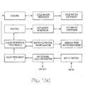
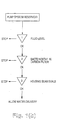
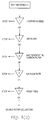
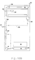
- the water collection and treatment processes of the present invention are shown in Figs. 1(a)- 1(c).
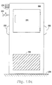
- Figs. 1(d) and 1(e) show design details of the dew-collecting surfaces of heat absorber 1.
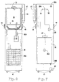
- the general configuration of the basic water collection system is shown in Figs. 2 - 4.
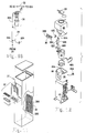
- the working components are enclosed in a housing (21) with a top cover, four vertical side panels and a base.
- the housing (21 ) may incorporate a bracketed opening in the rear cover panel opening through which is inserted an optional electronic air filter (38).
- the optional air filter (38) contains an optional whistling, audible warning device (38-A) which signals when the air filter needs to be cleaned. Other known warning devices may also be used.
- An additional optional fail-safe switch (38-B) prevents operation of the system when the air filter (38) is not in place.
- the housing (21) incorporates a front wall alcove opening and assembly (37) which consists of an alcove shell, grid and waste water receptacle; see also Fig. 11 for an exploded detail. Above the alcove is an optional low-light-level lamp, or "night light" (35).
- the alcove also contains a fluid delivery control (36) for dispensing ambient-temperature water.
- One panel of the housing (21) has an inlet opening into the air filter (38) which may include a whistling alarm device (38-A).
- One panel of the housing (21) provides an opening for air exhaust. This opening has an optional insect-resistant screen (49) on the interior of the housing (21) outlet port.
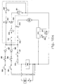
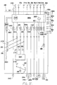
- safety fuse 20a 311 water-syst. main switch 20a 311 a spilled water sensor, signal 21 311A spilled water sensor relay 21 311B spilled water solenoid 21 311C spilled water alarm light 21 311D audible signal - spilled water 21 312 reservoir fluid lev. sensor/switch 20a 313 circ. pump/UV indicator, lamp, LED 20a 314 circulation pump .
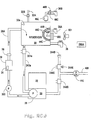
- Operation of the apparatus is initially controlled by the manual on/off switch (50) located on the housing (21).
- the variable-speed fan control switch (51) is adjacent to the on/off switch (50) on the housing (21).Air Flow and Treatment. Air entering the housing first passes through the replaceable air filter(38) and across the optional, self-contained ionizing device (27). Air then is drawn past an optional heating strip and fan assembly (23). then across heat absorber-1 (22) and film-coated, dew-forming surfaces (24) by an optional multi-speed intake fan assembly (40-A), which is controlled by the optional multi-speed fan control switch (51). Liquid condensate flows by gravity into the enclosed sump (25) and pump system reservoir (26).
- the pump system (26) has a self-contained switch and liquid-level sensor which shuts off heat absorber-1 (22) when the reservoir is filled. From the pump reservoir. condensate flows through a section of tubing (26-A) and is recirculated through a bacteriostat subsystem i.e., a pump, carbon block VOC filter (31) and a ultraviolet germicidal light for killing bacteria (29).
- a bacteriostat subsystem i.e., a pump, carbon block VOC filter (31) and a ultraviolet germicidal light for killing bacteria (29).
- This subsystem is controlled by a fail-safe switch (28) connected to a fail-safe indicator light (28-A), as shown in more detail in FIG.13.
- the bacteriostat indicator light (28-A) is located on the housing (21). As shown in Fig.
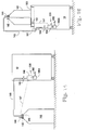
- heat absorber- 1 includes an array of extended-surface elements which are in good thermal connection with heat-sink contact zones at predetermined locations.
- the heat-sink points are mechanical-thermal connections adapted to remove heat from the extended surface and transfer it into an external environment.
- a variety of known heat sink techniques can be used to cool the surfaces of heat absorber -1 or -2, including classic boiling fluids contained in tubes, thermoelectric elements, and heat pipes.
- the heat-sink points are located at intervals of approx. 40- 100 mm along the vertical direction of the extended area.
- the section profile of the bottom of the collector tray may be rectangular or half circle. As shown in Fig.
- the extended surface elements are generally parallel and spaced apart a predetermined distance to avoid bridging over of surface waves due to heavy or maximum condensate flows and high air-flow velocities.
- the minimal condensate film thickness is indicated by dashed lines; this thickness corresponds to the condition when the air heaters are activated and operating at maximum power to prevent icing over.
- Water in the reservoir is recirculated through the bacteriostat subsystem, including the activated-carbon VOC final filter system assembly (31).
- the final water filter is fitted with a replaceable activated-carbon VOC adsorbent cartridge which is capable of removing organic contaminants, cysts and heavy-metal compounds.
- Processed water is then held in fluid reservoir-1, (30), which includes an optional form-fitted insulating jacket (34); through use of a manual (32) or electronically-controlled diverter valve (32-B), processed water can also be delivered through a35diverter valve outlet (32-A) to a large external collection container.
- the water level in the fluid tank (30) is controlled by the electrically-operated sensor switch and lid assembly (.33), which causes the pump (26) to cease operation when the fluid tank (30) is filled.
- Ambient temperature water is dispensed from the fluid reservoir (30) via the ambient fluid delivery control (36).
- Disposable liquid containers e.g., paper cups, suitable for cold water, are provided from optional attached dispenser (47) mounted on the side of the housing.
- fluid reservoir-1 (30) is removable from the housing for cleaning without removing its insulated jacket (34). This is accomplished by pulling aside the level sensor and lid assembly (33), which remains in the unit.
- the ambient fluid delivery control (36) remains affixed to the fluid tank (30).
- the fluid tank (30) can be cleaned using cleaning materials appropriate to its materials of construction and in accordance with public health requirements governing use of cleaning materials for food handling and potable water systems.
- mechanical removal of fluid reservoir- 1 (30) is simple, and can be accomplished without disturbing the permanent tubing connections.
- the housing (21) may be fitted with an optional ozone generator (39) adjacent to the departing; air stream to further improve air quality.
- the housing (21) may also contain an optional warbling, ultrasonic pest-control device (42) which operates continuously.
- four casters or rollers (41) suitable to the weight and size of the present invention may be affixed to the four comers of the lower side of the base of the housing (21).
- Optional carrying handles, suitable to the weight and size of the present invention may also be fixed, one on each side of the housing (21) at a height appropriate for transport by two adults.
- Model 2 As shown in FIGS 5-7. another embodiment of the present invention, Model 2, contains all elements of the basic model and also dispenses chilled water at a nominal temperature of 5° C in addition to ambient temperature water. The chilled water is produced by alternative methods.
- the first method is to incorporate a secondary heat sink, heat absorber-2, (43), which is controlled by the cold water temperature sensor and switch assembly (43-A).
- the heat-exchange probe (44) of heat absorber 2 is positioned between the insulation jacket (34) and the cold fluid tank (30A).
- An insulated baffle (45) is located in the cold fluid storage tank (30A) allowing for ambient water to be stored above the baffle and chilled water to be stored below the baffle.
- Chilled water is dispensed via the chilled fluid delivery control (36-A).
- the second method which is shown in FIG. 20d, includes an electronic, thermoelectric cooling module 44, the exterior portion of which is cooled by a fan 44A.
- the ice finger or probe (46) of the module 44 protrudes into the storage tank.
- an interior enclosure 44B is placed around it.
- the enclosure is sized according to the expected demand for cold water and it has orifices or holes 44D to allow entry of ambient water when the cold water valve, which extends into enclosure 44B, is opened.
- An exterior enclosure 44C with holes 44D is spaced over 44B to provide a convection-resistant, insulating water layer between the chilled zone and the ambient zone.
- the holes of 44B and 44C are sized and aligned so that radial or through-flow is prevented.
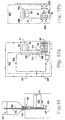
- Model 3 includes all of the elements of the basic model and Model 2, but also dispenses heated water at a nominal temperature of 75° C. Hot water can be provided in two ways.
- the first method is to provide a hot water tank assembly (46) connected by means of a "quick" disconnect connection assembly (52), which is described below.
- the hot water tank assembly (46) includes a sealed stainless steel tank of the appropriate grade and type of stainless steel utilized for food handling, provided with an electric heater and insulating jacket (46).
- Temperature of the hot water is controlled by a heated water temperature control sensor and fuse assembly (46-A).
- a dispenser (47-A) for disposable liquid containers, suitable for hot water, is attached to the side of the housing.
- a quick-disconnect system (52) links the hot water tank (46) to the ambient fluid delivery control system by means of a "tee" connection.
- the same quick- disconnect system (52) links the heated fluid delivery control (36B) to the hot water tank assembly (46) to enable easy removal of the cold fluid tank (30) for cleaning, without the need for manual connections and disconnection of plumbing. As shown in FIG.
- the quick-disconnect system (52) consists of a pair of receiver adapters, as follows: male adapter A) connects with female receiver (52-B) to carry ambient temperature water into the hot water tank assembly (46). A male adapter (52-C) connects with female receiver (52-D) linking the hot water storage tank (46) with the heated fluid delivery control (36B). The tube divider (46-B) physically separates the adapter system tubing and connections.
- This quick-disconnect system allows for removal and reinstallation of the main water cold fluid tank (30) without manual interference with the refrigeration system, the water tubing or the hot water tank fittings.
- the second method is to add an in-line heater to the delivery line for heated water.
- the heater (46C) is actuated by switch (46B).
- the heater is a stainless steel, in-line, electric-resistance heater such as used in coffee makers.
- the heating element provides sufficient thermally-connected area to the flowing heated-water stream by selecting its length, i.e., it is long enough and hot enough that the water is sufficiently heated when it reaches the delivery valve (36B).
- the in-line heater is activated to operate only for a sufficient time, which is defined by preset timing relays and triggered by a push-button switch (46B).
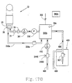
- Model 4 As shown in Figs. 22-24, another embodiment of the present invention, Model 4, contains many of the same elements of the basic model but employs a combined condensate collector and storage reservoir. Referring first to Fig.
- the dehumidifier's compressor (510) and its evaporator (512) are essential elements of dehumidifier's heat exchanger and are enclosed in a housing (508).
- the compressor is operated initially by an on/off switch (514) which, in the preferred embodiment, is a circuit breaker.
- the housing has an upper and a lower chamber separated by a horizontal partition.
- a fan (516) draws warm air through an air filter (518) optionally meeting HEPA standards, and blows it across the cool evaporator to drip into the funnel (520).
- the funnel penetrates the horizontal partition to allow condensate to be discharged into a combination condensate collector and storage reservoir (522).
- An optional ion generator (524) is placed before the air filter (518) to further assist in removing particulate matter from the intake air and to impart a negative charge to the discharged air.
- a heater (526) within the housing is thermostatically controlled to prevent the apparatus from freezing when operated in remote locations.
- Switch (528) is either a float switch or an electric switch and cuts off power to the pump (530) to prevent condensate overflowing the combined condensate collector and storage reservoir.
- the condensate in the combined condensate collector and storage reservoir is sealingly connected to the pump (530), the NSF 53 water filter (532), and the bacteriostat (534) by discharge line (536) which extends through the housing to a quick disconnect point (538A). If the quick disconnect fittings do not have automatic closure when disconnected, valves (572) or end plugs attached to quick disconnect points (538, 538A) close off the water lines.
- An alternate location (540) for the bacteria killing device (534) is in the combined condensate collector and storage reservoir (522) itself.
- the optional leak detector switch (542) is located in the bottom of the housing and if spilled or leaking water is detected, shuts off power to the apparatus.
- the recirculation loop (544) is connected to the discharge line (536) by a quick disconnect (546). If there is no recirculation line, it is terminated at (546) with an end plug.
- a recirculation solenoid (548) opens and closes periodically as controlled by a pump timer (550) at the same time as pump (530) is actuated to allow treated water to be recirculated into the combined condensate collector and storage reservoir (522).
- a pressure switch (552) electrically connected to pump (530) senses the pressure in the water line and any time any dispenser (554), (556), (558) opens and water pressure drops, the pump (518) turns on. It is deactivated when the dispenser is closed causing pressure to return.
- a low condensate switch In the bottom of the combined condensate collector and storage reservoir (522) is a low condensate switch (560) which can be either a float switch or electronic switch. If there is low water, an electrical signal is sent to inlet water solenoid (562) which opens, letting municipal water (564) pressurize the system.
- a check valve (566) is installed in the combined collector condensate and storage reservoir discharge line (536) to prevent municipal water pressure from filling combined condensate collector and storage reservoir (522). When a dispenser is opened, municipal water (564) flows through the deactivated pump, the water filter, and the bacteria killing zone in the bacteriostat to the open dispenser.
- the flexible discharge line (568) is shown connected to a refrigerator's (570) ice maker (558) with quick disconnect fitting (538).
- a cut off valve (571) is installed to allow easy variance of the length of flexible tubing water line (590). If the quick disconnect fittings do not have automatic closure when disconnected, valves (571) or end plugs attached to quick disconnect points (592, 592A) close off the water lines.
- the ice maker's timer (574) opens the internal ice maker valve ; water is discharged into the ice tray (576).
- the compressor (510) can be enabled to activate until it frosts over and then deactivate until the frost melts, producing condensate.
- the evaporator (512) will freeze.
- the compressor can be enabled by timer (598) to activate and deactivate to produce condensate.
- timer 598
- the maximum condensate production for any model can only be determined by engineering tables and by testing in a controlled environmental test chamber. From the results of those tests, a computer program is written and programmed into an optional timer (598) that controls the on/off cycle of the compressor (510) for maximizing condensate for each temperature/humidity combination.
- the housing of the apparatus has an optional thermostat and humidistat (600) which sends the current temperature and humidity to the computer programmed timer (598) to maximize condensate collection.
- the programmed timer (598) and the thermostat/humidistat (600) are optional as they would not be needed in some climates.
- the recirculation loop 544), the recirculation solenoid (548), and the pump timer (550) are optional as some water generators are expected to be used continuously rather than periods of prolonged absences (i.e. vacations).
- the optional operation display panel (602) contains some or all of the following operational items: an on/off switch (514); a fan speed control (603); a humidistat/thermostat (600); bacteriostat safety switch (610); a total production digital counter (606) for determining when the water filter (532) is to be changed; recirculation switch (608); overflow indicator (609); and other indicator lights for monitoring system operation.
- a humidity/temperature, water production chart (607) showing the expected water production at various combinations of temperature and humidity is created accordingly and can be posted.
- the optional digital water level sensor display (604) of the combined condensate collector and storage reservoir (522) can also be programmed so that it would also act as the low water switch (560).
- the optional total production digital counter (606) counts the gallons of water processed so that the time to change the water filter (532) may be determined.
- the flexible tubing inlet water line (590) and the flexible discharge water line (568) are shown encircled by a sleeve or jacket (594).
- a sleeve or jacket (594) Use of the sleeve (594) is optimal when these lines are exposed as it provides for neat, unobtrusive location of the lines.
- the elongated portion of the sleeve (596) is for easily attaching the sleeve and the tubing to the wall. Both sides of the sleeve could be elongated if desired.
- FIG. 24 is a cross sectional view of this embodiment oriented vertically to facilitate a floor standing model. While the wall hanger housing (508) is longer than it is tall (shown in FIG. 22), the floor model housing (584) is taller than it is wide. The built in housing dispenser (550) does not prevent other remote dispensers from being added if desired. Optional connection of municipal water (564) is still available and all the features of the wall model are all the same.
- the floor model includes optional wheels (586) and handles (588).
- heat absorber 1 produces condensate on an inert-coated surface (24).
- Incoming air is filtered by a known depth-screen filter assy. or an optional electrostatic filter assy. including the filter (38), a filter warning whistle (38-A) and the air-filter fail-safe switch (38-B).
- An ionizer (27) puts a negative electrical charge onto particulate matter in the incoming air stream to assist in the trapping of particulates in the electrostatic filter.
- an optional ozone generator (39) can be included; this addition allows the present invention to function as a charged-particle generator and room-air purifier.
- a pumping reservoir assembly In this assembly there is a self-contained float switch which actuates the condensate pump when a predetermined water level is reached.
- the condensate is conducted through UV-transparent tubing (26-A) prepared to comply with medical and human food-handling requirements.
- the condensate is subsequently exposed in multiple passes to a bacteriostat, or apparatus for killing bacteria, such as an ultraviolet germicidal light, (29) or other known UV source capable of producing radiation for effective killing of water-borne bacteria, viruses and organisms.
- the bacteriostat (29) is monitored by the fail-safe switch (28). Multiple passes through the UV and carbon block VOC filter portions is accomplished by activating the recirculation pump at least once at predetermined time intervals in the range 1- 12 hours, for a predefined flow or time duration in the range 1-50 times the reservoir volume or 1- 200 minutes at a specific flow rate. By this repeated process, water is intermittently and continually recirculated across the VOC filter and UV portions of the purification circuit whenever the water generator is in use. The flow duration may be defined by the volume circulated or by time.
- a fail-safe indicator light (28-A) on the exterior of the housing (21) confirms proper operation of the bacteriostat. If the bacteriostat is not enabled, as indicated by the light being "off, operation of the entire machine is stopped and an audible alarm is activated.
- the condensate is pumped under positive pressure through an activated-carbon VOC adsorbed purification filter assembly capable of NSF-53 purification. and then pumped into fluid tank (30), or (30A) for Model 2 or 3, of plastic or stainless steel as is common for food-service contact.
- the fluid tank may be encased by an optional, form-fitted insulation jacket (34) made of a nontoxic material, such as polymer foam.
- a fluid delivery control (36) is installed into the storage fluid tank (30) using nontoxic sealants suitable for contact with potable water intended for human consumption.
- the fluid tank (30) in one embodiment, is removable for cleaning.
- the fluid delivery controls (36, 36-A, 36-B) are at an ergonomically-correct level above the floor, making water easily accessible for children or persons in wheelchairs.
- An optional holder (47) for disposable cold-liquid containers is shown in close proximity to the fluid delivery controls (36).
- a manually operated diverter valve (32) allows the potable water to be pumped to a remote cistern. Diverting the water flow does not prevent dispensing water from the storage cold fluid tank, provided that the tank contains water. In some models the diverter valve is electrically operated and water is automatically diverted whenever the reservoir tank is filled.
- the cold and ambient fluid delivery control (36-A) and (36) extend from the fluid reservoir-1 (30) through the front of the housing (21) into a common dispensing alcove assembly (37) containing a grill-type drain insert to collect waste water.
- An optional night light (35) above the alcove provides illumination for water dispensing during periods of darkness or low light levels.
- An optional multi-frequency ultrasonic pest control device (42) and optionally for models, extraordinary attention to sealing the housing (21) with nonporous, nontoxic sealants allows the open-air version of the present invention to operate for extended periods of a month or more indoors or outdoors without human tending.
- Model 2 contains all subsystems which allow it to produce and dispense chilled water in addition to the ambient temperature water.
- the chilled water is at a nominal temperature of 5° C. Chilling of the collected purified water is accomplished by adding a secondary cooling device, heat absorber-2 (44).
- the surface (44) is positioned between the insulation jacket (34) and the bottom of the fluid reservoir- 1 (30).
- heat absorber 2 is a cooling finger extending into the reservoir.
- an insulated baffle (45) is placed in the fluid reservoir-1 (30A) allowing for ambient water to be stored above and cold water to be stored below.
- the cold water below the baffle is delivered through the cold-fluid delivery control (36-A);
- the ambient-temperature water is delivered through the ambient temperature fluid delivery control (36).
- Both fluid delivery controls protrude from the fluid reservoir- 1 (30) through the front of the housing (21) into the dispensing alcove assembly (37). Because the fluid reservoir-1 (30) in one embodiment is removable for cleaning without dismantling the internal mechanisms, the present design represents a significant improvement over old-art systems.
- Model 3 of the present invention includes subsystems which permit it to produce and dispense heated water in addition to ambient-temperature water and chilled water. Heated water is dispensed at a nominal temperature of 75° C.
- Heating of the water is accomplished by adding a heated water tank assembly (46) comprising a stainless steel tank in compliance with food-handling codes, a heater, an insulated jacket and a electrical, fused water-temperature control assembly (46-A). Ambient temperature water is drawn into the hot water tank through a quick-disconnect "tee" fitting behind the ambient temperature fluid delivery control (36). Hot water is dispensed through the hot fluid delivery control (36-B), which is connected to the hot water tank assembly (46).
- the quick-disconnect receiver-adapter assembly system (52) allows easy removal of the fluid reservoir-1 (30) for cleaning, without the need for manual connections and disconnections.
- the ambient temperature water portion of the assembly consists of a quick disconnect male adapter (52-A) that mates with the quick disconnect female receiver (52-B) to supply incoming water to the water heater tank(46).
- the heated water portion of the assembly in one embodiment consists of a quick disconnect male adapter (52-C) that mates with the quick disconnect female receiver adapter (52D) to supply heated water to the hot fluid delivery control (36-B).
- the water-heating feature of this invention may be supported by adding a known, in-line water heater to the hot-water delivery line. This unique disconnect concept represents a significant design improvement over old-art systems.
- Model 4 of the present invention includes sub-systems and design changes which permits it to operate with a combined condensate collector and storage reservoir (522).
- the housing of Model 4 has an upper and a lower chamber separated by a horizontal partition.
- a fan (516) draws warm air through an air filter (518) optionally meeting HEPA standards, and blows it across the cool evaporator to drip into the runnel (520).
- the funnel penetrates the horizontal partition allowing condensate to be discharged into a combined condensate collector and storage reservoir (522).
- the condensate in the combined condensate collector and storage reservoir (522) is sealingly connected to a pump (530), an NSF 53 water filter (532), and a bacteriostat (534) by discharge line (536) which extends through the housing to a quick disconnect point (538A).
- a low condensate switch In the bottom of the combined condensate collector and storage reservoir (522) is a low condensate switch (560). If there is low water, an electrical signal is sent to inlet water solenoid (562) which opens, letting municipal water (564) pressurize the system. Accordingly, condensate from the combined condensate collector and storage reservoir (522) or municipal water (564) can be automatically dispensed through the bacteriostat (534) if a pressure drop is sensed by pressure switch solenoid (552) as a dispenser (556) or an appliance's timer (574) is opened. The pressure switch solenoid (552) turns off the water flow when pressure builds back up after the dispenser is closed. The force of the water is dependent upon the amount of water in the combined condensate collector and storage reservoir (522) as determined by low condensate switch (560). Remote dispensers as well as municipal water sources are attached by quick disconnect fittings.
- the compressor (510) can be enabled to activate until it frosts over and then deactivate until the frost melts, producing condensate.
- the evaporator (512) will freeze.
- the compressor can be enabled by timer (598) to activate and deactivate to produce condensate.
- recirculation switch (608) activates recirculation of water from the combined condensate collector and storage reservoir (522) through the bacteriostat (534), the water filter (532) as timed by pump timer (550).
- the invention may be connected to various dispensers remotely located through tee connectors and quick disconnect fittings.
- An operation control panel (602) contains various indicator displays electrically or audibly indicating system operation.
- a humidity/temperature water production chart (607) showing the expected water production at various combinations of temperature and humidity can be created according to testing conducted in a controlled environmental test chamber. This graph can then be posted on the outside of the cabinet (508) to show expected water production.
- Examples M1 and M2 below give technical parameters for the design and inert surface coating of the extended heat-exchange area of heat absorber 1, i.e., the air cooling and dew-collecting surface.
- Example M1 Extended heat exchange area.
- Incoming ambient air at a velocity of 1-10 meters/sec is cooled below its dew point by circulation across an array of generally-vertical, spaced-apart, cooled surfaces shaped and oriented to drain collected liquid dew dropwise from a pointed zone on the bottom edge.
- the active extended cooling area for both sides of each30element in the array is in the range 100- 500 cm2; the total active area of the array is in the range of 1- 4 m2.
- the general outline shape of the dew-forming elements is shown in Fig. 1(d).
- the height dimension of each cooling element is in the range of 15- 40 cm; the element width dimension is in the range of 3- 10 cm.
- the height dimension is measured generally parallel to the gravity vector; the width dimension is measured, generally perpendicular to the gravity-force vector.
- Each element is formed from one or more sheets of high thermal conductivity material of thickness in the range 0.2- 1.5 mm.
- the average center-line spacing of adjacent cooling elements is in the range 3- 10 mm.
- the profile may be either parallel - planar elements, as shown in Fig. 1(e) or parallel - corrugated elements.
- Parallel -corrugated elements may be prepared by 3D forming of planar elements to include an array of ridges and valleys arranged parallel to the vertical or at an acute angle in the range 1- 15 deg. to the vertical.
- surface waves formed on the maximum-thickness draining liquid condensate layer do not bridge across the element spacing.
- Heat absorption from the extended area can be accomplished by a variety of cooling means thermally connected to the area; such cooling methods include refrigerant-expansion coils, thermoelectric coolers, heat pipes, etc.
- the design of heat absorber 1 includes defining the number, size and placement of cooling conductors to cool the extended surface elements. In the case of cooling by a boiling liquid in contained tubes. the tubes are oriented generally horizontal and perpendicular to the extended surface plane. Several refrigerant tubes of 3- 6 mm diameter spaced apart at a distance of 40- 100 mm have been found to provide effective cooling.
- Extended surface elements may be formed from thermally-conductive metals, alloys, ceramics/ glasses and polymer composites including alloys, Cu, alloys, Al-filled amide or olefin polymers and ceramics.
- Example M2 Inert surface coating.
- all such exposed, cooled surfaces are coated with a continuous, thin, inert, food-grade film of polymer such as siloxane, PTFE, urethane, olefin, etc.
- All exposed surfaces of the heat absorber which come into contact with liquid dew are cleaned to remove surface contaminants such as grease, oxides and other adventitious residues prior to the initiation of the coating process.
- An inert coating of thickness in the range 0.01- 0.2 mm is then applied by known methods such as spraying, dipping, electrostatic coating, etc.,. After application and curing, the film coating is then cleaned to remove any volatile or extractable components which might contaminate the dew or water being-produced.
- Example M3 Air Filters, Alarms and Interlocks.
- the first line of defense against insect penetration into the unit are woven-wire screens covering the entire area of both the inlet and outlet air ports.
- the screen mesh openings range from 0.3 mm to approx. 1.0 mm in diameter.
- the depth and screen elements of the air filter apparatus are prepared and sized to achieve approx. 99.99 % filtration of all solid particles of diameter greater than 1 micrometer for an air flow rate of 4- 9 m3/ min.
- the filter apparatus may also be fitted with a pressure-drop sensor which will permit buildup of collected particles of approx. 65% of the limit capacity of the element before an alarm condition is signaled; the optional filter-overload alarm may be an intense, high-frequency acoustic whistle or other known alarm device.
- the air filter may also be fitted with gas-ion generators, alpha- or beta- particle emitters, such as radioisotopes, electrostatic charging devices, such as agitated filament arrays or high- voltage corona wires, which facilitate retention of smaller, less-dense airborne particles.
- the air filter may also be fitted with an optional interlock switch which prevents operation of the entire generator if the element is incorrectly positioned or an incorrect size is used.
- Bacteriostat System and Interlocks The bacteriostat system includes two stages: (a) an active killing stage for microorganisms and (b) an activated-carbon VOC adsorption stage for removing undesirable and toxic organic impurities which are present as vapors in the ambient air and will be dissolved in the condensate water produced.
- the killing stage may employ electromagnetic radiation, such as UV or gamma, of selected intensity and wavelength, to kill adventitious bacteria and viruses which are present in the condensate water.
- electromagnetic radiation such as UV or gamma
- the killing stage may employ one or more physiologically-tolerated oxidizing chemical species such as ozone or hydrogen peroxide for killing bacteria. It is of course important to provide an exposure chamber which allows the condensate water to be exposed to or circulated through the killing zone.
- Either the UV source or the chemical generator may be fitted with positive interlocks which shut down the delivery pump if the device is not operating within control ranges of wavelength, intensity or sterilization-agent dispensing rate.
- Example M4 UV germicidal lamps.
- the simplest killing stage includes a high-intensity, short wavelength ultraviolet lamp, UV sterilizing device, and fusible link interlock with the recirculation pump. Should the UV lamp fail to operate at an effective wavelength and intensity, electrical interlocks prevent the circulation pump from operating; in this event, no water can be delivered from the generator.
- the UV generator can be: (a) mounted into the cover of the reservoir for direct exposure or (b) mounted adjacent to a section of low-pressure tubing which transmits the effective radiation wavelengths through the water.
- quartz known UV-transmitting glasses, polymers or ceramics may be used for the UV-lucent tube zone.
- the treatment zone or chamber must also be fitted with UV reflectors to maintain a high intensity level of the effective wavelengths and prevent accidental personnel or user UV exposure during maintenance work.
- the GE model T5 has been found to give good results.
- UV sources can be adapted to operate with the present invention; these include electronic solid-state UV devices, natural sunlight light pipes, and fluorescent/ chemiluminescent sources.
- an ozone generator or an intense ultrasonic field may also be used for water sterilization.
- the ozone systems operate by electrochemical formation of microbubbles of O3 in the condensate water.
- Known piezoelectric or magnetostrictive ultrasonic probes can be fitted to a section of tubing or mounted to immerse the probe into the reservoir tank.
- Example M5 Ozone Gas Generators for Air Freshening.
- Gaseous ozone is thought to assist in removal of undesirable vapors and aerosols from the ambient air.
- An optional ozone generator can be mounted in the air-handling section of the present invention.
- Several alternative ozone generators have been evaluated for conditioning the air being circulated through and discharged from the present water generator; the most cost-effective seems to be the Bora model from Alpine Ind.
- other electrochemical generators can be used to generate or release sterilizing gases; one example is the release of halogen gases based upon metered injection of compounds which decompose spontaneously or which can be electrochemically dissociated in liquid solution.
- Example M6 Air Ionization Pre-Treatment.
- Electrostatic charged-particle generators of various types such as polonium strips and Sanyo HAF 3000 ion generators have been evaluated and found to work well with the present air filter for removing aerosol particulate contaminants.
- Charged particles emitted from the generator impart a charge to the particles which makes them easier to filter.
- Such modules are connected to the main controls with a fail safe circuit to prevent operation if the ionizer is not operating within control limits.
- Alternative embodiments f the present invention using other sources of charged particles including alpha particles, beta particles, and charged ions may be used.
- isotope mixtures and/ or decomposition-result alloys of radioactive metals such as radium and polonium are useful charged-particle sources; since such emitters can be made with controlled particle fluxes, small area sources are also possible.
- the simplest and least expensive absorber for volatile organic compounds, VOCs includes a porous activated-carbon block VOC filter; such a filter is connected in series with the UV sterilization device. At a flow of 0.8 to 2 liter/ min, the cartridge is capable of trapping 1- 2 micrometer diameter suspended particles, removing taste and color bodies and reducing dissolved toxic hydrocarbons to acceptable levels for safe drinking water according to ANSYNSF-53. Before this filter becomes substantially blocked. an integrated output flow meter indicates the cumulative volume of water treated by the VOC filter. Preferably, this indicator or display can be seen from the rear exterior of the unit.
- Known mechanical. electromechanical or electronic volume-measuring devices are used to display the remaining design capacity of VOC filter.
- Water is continually recirculated through the UV and activated carbon units when the generator is "on".
- a number of known carbon-block filters are found to perform reliably to NSF-53 standards; one acceptable filter is the Amtek C240 MMB.
- water delivered from any output valve, including, cold. ambient, hot and the diverter valves will have passed repeatedly through the VOC filter and the bacteriostat unit.
- Example M8 Alternative working fluids in compression refrigerator cooler for heat absorber- 1.
- Approved working fluids for high-efficiency reverse-cycle equipment fall into two main classes: high temperature and low temperature.
- So-called low-temperature refrigerant fluids, such as 406A operate at lower temperatures and lower pressures; use of such fluids can be significant for units operating in air-conditioned spaces.
- Example M9 Alternative heat sinks for units operating in air-conditioned spaces.
- heat absorber or heat absorber2 may also be desirable to reject heat from heat absorber or heat absorber2 into: (a) the frame and/ or surface skin of the enclosure or (b) the liquid condensate water collected below heat absorber-1.
- a mechanical refrigeration system. is used for heat-absorber-1, it is also possible to provide a thermal/ mechanical linkage from a portion of its evaporator section and its condenser, for the purpose of modulating the temperature of the exhausted air. In this embodiment, it is possible to use a lower flow rate of cooling air and thereby reduce the level of fan noise which is projected into the local environment.
- Example M10 Alternative controls for units used in air-conditioned spaces.
- the resistance-heating strip deicer as used for units operated outdoors, can be replaced by known thermostat/humidistat controls as typical for reverse-cycle appliances. This option is of interest for units used in a controlled environment.
- an external reservoir such as a 20-liter glass bottle or other container.
- the system dispensing controls for such an embodiment may be 10modified to connect with an appropriate ancillary liquid level or fluid-mass sensor for the external container to regulate water generation when the container is filled to capacity.
- Example M11-A - Ancillary external reservoir Example M11-A - Ancillary external reservoir.
- Version M11A shown in Fig.14, is an embodiment with no internal reservoir and a large-volume, covered vessel located on the floor beside the unit.
- This embodiment is a "cut-off" version of the simple embodiment shown in Fig. 2 wherein the housing is truncated by a horizontal plane at approximately the vertical height of the bottom of the alcove assembly, approximately 0.8 to 1.5 m above the base plane.
- the water output flow from the water generator is regulated by a solenoid valve (146) which is in turn controlled by a liquid level sensor (149) which is attached to the seal plug (142).
- the sensor and solenoid valve may be known low-voltage electric devices designed and certified for safe immersion in water or use in wet environments; alternatively the sensor and slave valve may be simple known fluid/ mechanical devices.
- the flexible external tube (143) and flexible low-voltage leads (147) may be enclosed in a flexible sheath (148) or tied together with known bands and methods.
- the external reservoir (141) is shown here as a vertical bottle standing close by on the base plane and fitted with a tight-fit removable seal plug (142) adapted to prevent entry of liquids or gases from the exterior into the port of the reservoir, it may also be possible to locate it at some distance 2-10 m at the same level, e.g., in another room or building. It may also be possible to locate it above or below the base-plane level , up to approx. 5 m level difference, by the addition of known precautions such as non-siphon check valves.
- Fig. 14 shows electrical/electronic sensors (149) and control valves (146), it is also possible to use magnetic, optical, acoustic, or mechanical level sensors and related water-flow control valves.
- the external-line valve (145) is shown as a simple manual valve, it is also possible to use an auto interlock device to detect: (a) whether the external reservoir is correctly connected, (b) whether the unit is powered, or (c) whether the water-generation switch is "on".
- Version M11B shown in Fig. 15, is an embodiment with no internal reservoir and an adjustable weight or mass-sensing device mounted on its top surface, which supports an external vessel.
- the top surface is a "cut-off embodiment- similar to that shown in Fig. 14.
- the mass-sensing element serves to shut off the solenoid valve when the container it supports is filled to capacity.
- containers of differing empty weights and internal capacity can be used, i.e., 4-liter, 8-liter, 20-liter.
- the external container is placed on a weighing plate (153) secured to the top surface of the truncated housing.
- a pivoting weighing plate shown in Fig. 15 is subject to the downward load of the reservoir and its contents and to counter forces(15 1) which keep the weighing plate approx. level, i.e., at an angle of less than 5°
- Alternative support embodiments for a non-pivoting weighing plate may include arrays of 1 -10 compliant elastomer elements or spring elements.
- the counter force (151) can be applied at a plurality of points to support the weighing plate (153), i.e., the counter force may be provided by 1 - 10 resilient elements of differing or variable characteristics to allow for use of containers of different sizes or tare weights.
- the simple flat plate (153) shown in Fig. 15 can be replaced by a shaped weighing platform having an engagement or retention zone for the bottom of the reservoir, e.g., a recess or pocket, an array of projections, a tie down strap, or snap-in anchor latches for an externally- grooved reservoir.
- the electronic weighing sensor (152) shown in Fig. is connected by low-voltage leads to the solenoid valve (154); when the container is filled to capacity, its total weight reaches the predetermined value built into the country force (151) and the weighing plate triggers the sensor (152). It is also possible that the signals from sensor (152) can provide valuable control outputs to regulate the operation of the water generator, i.e., if the reservoir contains at least a predetermined quantity of water and the time of day falls in the period 1700 to 0600, the logical management algorithm may be programmed to defer operation of the generator.
- the manual water flow control valve shown in Fig. 15 can also be replaced by a solenoid and electrical/ electronic sensors to detect: (a) whether the external reservoir is correctly connected, (b) whether the unit is powered, or (c) whether the water generation switch is "on".
- Example M11-C - Retrofit kit for typical bottled-water dispensers
- Version M11C shown in Fig. 16 is a retrofit embodiment which can be installed to modify a typical gravity dispenser as commonly used for standard bottled water.
- Such dispensers can be easily converted to use water generated by the present invention by installing a vertical water delivery tube to the rubber seal collar; this tube is fitted with integral water level sensor located at the uppermost end.
- the water generator with a reduced-volume internal reservoir may be located adjacent to or beneath the existing water dispenser.
- a vertical, water-delivery tube of appropriate material for potable water will be installed as a modification of the existing bottled-water dispenser.
- the length of the vertical tube and the specific position of the water-level sensor can both be adjusted to accommodate different sizes of supply bottles and different seal collar designs.
- the water level sensor serves to shut off the solenoid valve of the water generator when the water bottle on the dispenser is filled to capacity.
- the sensor and solenoid valve may be low-voltage electric devices designed for immersion in water or wet environments; alternatively the sensor and solenoid valve may be simple fluid/ mechanical devices.
- the level sensor (162) is installed at the uppermost end of the water inlet tube (163) and the air-vent tube (164).
- the mod. kit also can also include a seal adapter plug (16 1) if the existing collar does not lend itself to retrofit. For the possible cases in which the existing collar and piping are extremely difficult to connect, the retrofit kit can include an embodiment with flexible connections between the existing system and the new seal adapter (161).
- the flexible zone and sheath (165) consists of sheathed, flexible connections to the level sensor (162), vent tube (164) and water tube (163).
- the conversion kit can be provided with a lengthened flexible zone. This will permit insertion of the seal adapter (161) along with the elongated tubes (163) (164) into a typical filled supply jug held with its mouth facing upward beside a typical cabinet, the length of-the flexible zone is in the range 0.2 to 1m. When the jug is lifted into position on the cabinet, the excess length can be concealed inside the typical cabinet.
- the level sensor (162) 20 detects that the jug is filled to a predetermined level, it sends a signal back to the solenoid control valve of the water generator through the low-voltage leads; this signal stops the flow of water into inlet of the water tube (163).
- a "cut-off" embodiment of the present water generator similar to that shown in Fig. 14 is placed beside the existing bottled-water dispenser. Any embodiment of the present invention can be fitted with an external port for providing impure water into the recirculation loop in case of low temperature or humidity in the local environment. This operation provision will also enable the unit to dispense a much greater volume of potable water than would ordinarily be possible by condensation alone.
- an additional alternative system to dispense and meter drinking-water additives such as colorants, flavoring, medicaments, vitamins, mineral supplements, etc. can be added near the end of the RT or cold-water delivery line on any embodiment of the present invention.
- Example M12 Water generator for use in vehicles subject to violent motions and tilt angles .
- the present invention may be fitted with two changes to meet these needs: (a) gimbalsuspended, sealed condensate collector and (b) enclosed, sealed potable water reservoir with an appropriate vent.
- porous, hydrophobic foam elements may be attached to the upper wall zone of the tray to cover any gap between it and the edges of the heat-exchange plates or fins.
- the collector tray may also be prepared with internal baffles plates extending perpendicular from the bottom or sides to suppress splashing.
- Example M13 - Combination refrigerator and water generator Example M13 - Combination refrigerator and water generator .
- a further embodiment of the water generator is to incorporate it with the cooling and auto ice making subsystems of a refrigerator to produce a hybrid appliance which both cools food and generates its own mineral-free potable water for dispensing directly as ice water or for automatic preparation of mineral-free ice cubes.
- approach (b) the difference between approach (b) and approach (c) is that the fluid fittings and electrical circuits from the modification kit is attached at predefined points, but not to factory-installed fittings or interfaces, to existing systems of the appliance; it is anticipated that approach (c) may be done "on site” or in a repair shop.
- a combination-hybrid appliance which is the combination of the water generator of the present invention within the cabinet of an appliance such as a refrigerator-freezer, icemaker or room air conditioner.
- the water generator may be: (a) provided with its own independent cooling systems in addition to the systems normally provided for the basic appliance or (b) integrated into or interconnected with the reverse-cycle system of the appliance so that only one compressor is used.
- Figs. 17a and 17b show front and side views respectively of one possible embodiment of the present invention as integrated with a vapor-compression refrigeration-type appliance such as a refrigerator-freezer, icemaker, room air conditioner or a local air-handler.
- a vapor-compression refrigeration-type appliance such as a refrigerator-freezer, icemaker, room air conditioner or a local air-handler.
- These figures show the outlines of the enclosure of a typical refrigeration-type appliance, and the flow diagram for the liquid and vapor refrigerant through the compressor, expansion valve and condenser.
- One embodiment of the present water generator is also shown as an integrated sub-system including indicia for its key elements as they can be placed in this embodiment.
- the water generator is shown on the right side of the main appliance; air from the space is drawn into the front of the water generator portion and exhausted toward the rear. While the alcove (37) and delivery valves (36), (36A), (36B) are shown facing toward the right in this example they may also face toward the front of the main appliance.
- the main compressor and main condenser carry the extra cooling load imposed by operation of the water generator, and its water cooler.
- the integrated water generator section would need only heat absorber- 1 (22) and heat absorber-2 (44) for its cooling requirements; both these are connected to draw liquid refrigerant from the main system. Fig.
- FIG. 17a shows phantom views of the reservoir (30), heat absorber-2 (44) and heat absorber-1 (22); the extended-area fins are shown in a cut-away view with a portion of the water-generator housing front-wall removed.
- the branching valve (171) may be included in the integral interface and installed during; manufacture of the main appliance; the attached or integrated water generator system may be fitted with a mating interface and splitter valve (171) which is connected to divide the liquid flow from (171) between heat absorbers- I and -2 of the water generator.
- the extended-area fins of heat absorber- I are shown in cut-away view with a portion of the water-generator housing side wall removed.
- the fins are arranged as a parallel stack with their flat faces parallel to the side. face of the main appliance.
- the water condensate collector is shown schematically as (25); the intake fan motor to circulate room air across the cooled surfaces of heat absorber- 1 are indicated as (40A).
- Essential systems of the water generator as described herein are enclosed within the housing (21); optional and other ancillary systems described can also be included within the enclosure (21). Further, it is possible for such integrated water generators. to use housings of smaller size and different shapes/ proportions as needed to assure high efficiency and consumer acceptance of the combined or hybrid appliances.
- Example M14 Combination water generator with: ice makers, air conditioners and dehumidifiers.
- the water generator of the present invention can be mechanically combined within the cabinet of appliances such as icemakers, air conditioners and dehumidifiers.
- the water generator may be operated to supply all or a large portion of the water requirements; for large-capacity units.
- the VOC filter loop of the present water generator can be used to purify the regular tap-water supplied to the unit. Since the water generator of the present invention uses certain systems which are already present in typical ice makers, air conditioners and dehumidifiers, it is cost-effective to add a certain level of marginal capacity in their cooling systems, generate potable water and provide it at one or more selected temperatures by means of permanent or quick-disconnect fittings/ mountings.
- the resulting hybrid appliance is thus capable of generating potable water which is compliant with NSF-53 purity standards as well as performing its normal function.
- disposal of water condensate from such units requires special drain piping and provision for manual emptying of the, collector. It is envisioned that the drained condensate from appliances such as an air conditioner may be recycled into the recirculation circuit of the present invention to provide additional potable water above the capability of the unit itself.
- Example M15 Evaporative-cooled spaces.
- the water generator of the present invention can be placed near a pool or other body of water or in an interior space which is cooled by water-evaporation air conditioning equipment for production of high-purity potable water.
- Example M16 Stand-alone refrigerator.
- Example M 13 An ice maker and integrated water generator which does not require a water connection.
- This example is an extension of Example M 13 above, which discloses an embodiment of this invention integrated with or into a refrigerator/ icemaker which requires a water supply for making ice, but generates its own potable water for dispensing.
- the water generator of this invention may be added : (a) as a field modification to a typical refrigerator/ icemaker or (b) a factory-integrated version.
- the resulting hybrid appliance has the capability of generating its own potable water which is available delivered as potable-water ice or dispensed as liquid potable water.
- Fig 18a shows a schematic refrigerant-flow diagram of one such embodiment. This particular embodiment includes two "AND" valves.
- Fig. 18b shows the schematic potable-water flow circuit including UV bacteriostat (201) and charcoal-type VOC filter (31) for removal of absorbable/ absorbable dissolved or dispersed contaminants.
- the filter (31) in this embodiment may be any known type of disposable filter which is able to reduce dissolved and dispersed impurities to low levels required by NSF Std.53.
- the filter may include screen, depth and porous adsorbent elements or stages prepared from known materials.
- the UV radiation module (201) can include any type of known UV source including gas plasma tubes, lasers, and solid-state UV sources. As shown, the return flow (209) passes through the active-radiation field of the UV bacteriostat (201).
- An additional feature of this embodiment is the auto-defrost water-recovery system which recycles melted frost from the freezer evaporator into the potable water circuit; the potable water circuit includes an "OR" valve (203) which is controlled to collect melted frost from the freezer during auto-defrost operations.
- This circuit includes a vented reservoir (207) and (30) respectively and a gravity-flow path (209).
- Example M17 Stand-alone icemaker with integrated water generator - no water connection required.
- FIG. 19a shows the front elevation view of a hybrid icemaker/ potable-water dispenser (230) which generates its own water supply by means of an integrated embodiment of the present invention.
- This unit may be floor supported as shown, or may rest upon a supporting surface (236), is moveable by one or two persons taking hold of the lifting handles (232).
- the general arrangement includes a hinged door (231) into the internal ice compartment; the icemaker freezes solid ice shapes and they fall into the holding bin as they are produced.
- the internal components include the water generator of the present invention connected into the refrigeration system of the icemaker.
- Such a unit may be made as a factory version icemaker or a field retrofit kit added to an existing standard icemaker.
- the unit may have one or more optional external delivery faucets for liquid potable water (233) at predetermined temperatures, e.g., room temp, cooled, or heated.
- the unit may also be fitted with an optional protective holder/dispenser means (234) to deliver clean, fresh, disposable drinking cups.
- a protective intake grille (235) is shown in front of the intake-air filter of the water generator.
- Fig. 19b shows a schematic view of one illustrative embodiment of the potable-water loop within the illustrative appliance of Fig. 19a.
- the shell of the cabinet is denoted as (240); one or more optional external faucets for dispensing potable water at one or more selected temperatures is indicated by (233).
- the cabinet is shown resting upon the floor or a supporting surface (236).
- the refrigeration system of the icemaker provides fluid to the heat absorber of the water generator (22) under the system control with user adjustments. Filtered environmental air is circulated across (22) and cooled; resulting liquid water condensate is collected in the collector (25).
- the electric pump (26) operates in response to control signals generated by the level controller, (202); this controller can enable pump operation to deliver condensate fluid to the pressurized reservoir (244) (a) upon call from the icemaker supply valve (247) (b) upon demand from the external potable-water dispensers (245) or at predetermined time intervals for the purpose of continual recirculation and resterilization of the reservoir contents through the UV radiation module (201).
- the UV exposure module (201) may be fitted with any UV source which produces effective wavelengths and intensities for sufficient time duration to effect killing of bacteria in the water stream; such UV sources include but are not limited to gas-plasma tubes, solid-state emitters, fluorescent emitters, natural sources, etc.
- This illustrative loop also includes a trim valve (241) which controls the water flow rate; for the simplest embodiment, it can be a known metering valve which may be manually preset to a selected max. flow when the pump is enabled for periodic recirculation or in any case when the water flow rate exceeds the sum of demands.
- this trim valve may include attached or integrated electromechanical or electronic sub-systems such as sensors/actuators/drivers responsive to digital/ analog user inputs to the control system(s)/algorithm(s).
- the filter (31) in this embodiment can be any known type of disposable filter which is able to reduce dissolved and dispersed impurities to low levels required by NSF Std.533.
- the filter may include screen, depth and porous adsorbent elements or stages prepared from known materials including but not limited to non-woven fabric, porous elements in the form of membranes, granules and other formed-media shapes and rings, saddles, etc. as well as bonded, porous charcoal preforms.
- the UV radiation module (201) can include any type of known UV source including gas plasma tubes, lasers, and solid-state UV sources. As shown, the pressurized return flow (243) passes through the active-radiation field of the UV bacteriostat (201). The wavelength, radiant energy level and water flow rate are adjusted to provide sufficient UV exposure for effective killing of bacteria As mentioned above the recirculation flow rate is limited by the trim valve (241).
- This illustrative embodiment includes a pressurized reservoir (244) fitted with a gas-filled bladder or an airspace as shown; the reservoir water-inlet check valve (246) prevents water from flowing backwards from the reservoir and into the supply channel (242).
- the level of liquid water in the reservoir is controlled by (206) which senses the level and/ or pressure; it is responsive to system control signals for maintaining the water level/pressure according to demand for ice or potable water or preset system commands for periodic recirculation of water already in the reservoir.
- Example M18 Vehicle Potable Water Apparatus.
- This embodiment is an example of a version of the present invention to produce potable drinking water from condensate available from auto or truck air conditioning systems or from other vehicular conveyances, such as trailers, mobile homes, cabin cruisers, etc., and dispensing hot and/ or cold potable water safely. See Fig 20(a) - (c).
- an enclosed reservoir (340) made of a UV-transparent polymer material, such as polycarbonate or acrylics, or is provided with a UV-transparent window (390) that is resistant to UV or oxygen degradation.
- the reservoir is provided with a safety-interlocked, enclosed (333) UV source (317) which may be located exterior to the reservoir and abutting either: (a) the UV-transparent window (390) or (b) a UV-transparent portion of the top or side walls.
- the UV source (317) is selected to provide a sufficient intensity and effective wavelength range for killing any live organisms present in the water being exposed within the reservoir.
- Another embodiment is to locate the UV source with a fluid-sealed, safety-interlocked, UV-transparent tube which traverses the reservoir interior.
- the reservoir has a fluid-level control sensor (312) that shuts off the circulation pump when low fluid is sensed in the reservoir. When the water level is low, the sensor shuts off the entire system.
- the light-emitting diode (LED) indicator display (308) also goes out at the driver's console (353) signaling a low water level.
- the reservoir has a drain valve (331) located at the lowest point for draining the system in the winter. In the case of a UV-opaque metal or alloy reservoir, it's inner surface may be polished or otherwise treated to increase it's reflectivity for UV wavelengths. If made of transparent polymer material, the exterior of the reservoir may also be wrapped with a UV-reflective metallic foil (341) to increase the killing effectiveness and power-efficiency of the source.
- the reservoir has one inlet for the incoming condensate (342) from the vehicle AC evaporator drain pan. It has two outlets. One outlet connects to the circulation pump (344) and the other outlet (343) connects to the overflow condensate.
- a controllable diverter valve (335) which allows condensate to go either to the reservoir or be discharged. This latter mode may be for seasons when the potable water system is not being used, such as in the winter, or for repairs or some other reason.
- the circulation pump may be located outside the reservoir or within in the reservoir. It is electrically connected so that it can operate only if the vehicle ignition switch is "on” (309), and either the hot (303) or cold (304) switch is “on” and the radiation source (317) fully operative. Downstream from the circulation pump is a check valve (345) that operates to keep the portion of the system downstream from it pressurized (363) when the circulation pump is stopped.
- the UV-radiation-treated water continues through a porous, carbon-block absorber filter (329) tested to meet NSF 53 standard for removing volatile organic compounds (VOC).
- VOC volatile organic compounds
- An additional line recirculates through the solenoid check valve (357) and flows past the UV source and the filter (329) and back into the recirculation chamber.
- the recirculating system control allows treated water to be periodically recirculated past the integrated radiation source (317) and the solid block VOC. filter (329). This recirculation takes place when the circulation pump (3, 14) is activated by a timing and valve sequence control (356).
- Controllable check valve (356) opens when the timer sequencer starts recirculating the water.
- a dispenser (360) and related control sensor may be added to the hot or cold delivery lines beyond the recirculating chamber, to allow delivery and accurate metering of certain desirable drinking water additives such as colorants, flavoring, vitamins, mineral supplements. herbal extracts, fluorine and other known therapeutic compositions.
- the recirculation assures that the water remains pure in the lines even after the vehicle air conditioning system has not operated for10extended periods.
- the energizing circuit for the timer-sequencer is electrically connected directly to the vehicle battery so that water is recirculated even when the vehicle is parked.
- Switch (359) disconnects the timer-sequencer from the battery when circulation is not desired such as in the winter or in extended storage.
- the hot water flow goes through a heater (328) with a heating element (321) and thermostat temperature-control switch (319).
- the hot water switch (303) is turned “on”, the heater is turned “on”, the LED indicator display (307) comes “on” showing the heater is “on”.
- the hot water safety interlock (305) is also energized.
- Switch (318) also prevents heater (328) from coming “on” if there is no water in the heater.
- the water reaches the appropriate temperature (about 80° C) it turns “on” the LED indicator display (320).
- Hot water for beverage service can then be dispensed by operating the controllable delivery valve (326) provided the arming switch, (350), on the driver console (353) is "on”.
- the interlock (306) ensures that no hot water can be dispensed by children or others unless the driver energizes both the main on-off switch (311) and the hot-water safety interlock switch (305). Once both these switches are “on”, water will be maintained at about 80° C by the thermostatic control (319).
- a check valve (327) in the line between the recirculation chamber and the heater (328) prevents hot water from leaking back into the cold water portion (347).
- the cold water flow line (347) is flexible, medical-grade tubing; this line passes through a portion of the cover (337) of the vehicle AC evaporator chamber and is thermally connected to. the vehicle's air conditioner cooling section (338). To increase the heat-exchange area, this line is formed with several loops and exits through the cold water safety interlock (306) and connects thence to the controllable delivery valve (325). Similarly, this delivery outlet may be branched or direct-connected to an external drinking-water supply tank, such as provided in atypical recreational vehicle. In case of low environmental temperature or humidity, it is also possible to introduce impure water into this system at port (334); alternatively, the unit may be primed with impure water to provide potable water in a minimal time interval after start-up.
- This example embodiment also illustrates some additional features including provision for fluidly connecting, either by quick-disconnect fittings or standard threaded plumbing connections, the apparatus to municipal water so that the apparatus will automatically admit and process municipal water whenever conditions are unfavorable or impossible for production of condensate to refill its storage reservoir.
- Quick-disconnect or threaded couplings may be provided for: (a) city/external-pressurized water inputs into the water generator or (b) for treated water delivery from the water generator to an external appliance such as refrigerator or ice maker.
- the control circuits are also adapted to admit municipal water automatically to external appliance(s), such as a refrigerator or icemaker, which is connected to the water generator, if its water-generation rate is not sufficient to meet the demand from the connected appliance(s).
- control circuit includes electronic logic components which examine operational status and sensed input parameters and, according to the predetermined logic, determine the need for and timing of switchover to municipal water.
- the logic devices evaluate the water level in the reservoir and the control circuits automatically operate appropriate electric solenoid valves in an appropriate sequence.
- the control circuit using similar electronic logic devices, automatically determines timing of switchover to delivering water output to an external system or diverting water to an external container.
- the control circuit also provides timing control for recirculation within the apparatus to remove dissolved substances and to inactivate bacteria.
- another embodiment of the recirculation system includes the recirculation line (243a), a pressurized reservoir (303b) and a booster pump (300) for feeding fresh condensate into the reservoir and either to an external container or to an external system.
- the status of the external system or reservoir i.e., "ready” or “off, is sensed by the pressure sensor (302) in the discharge line and a corresponding status signal (302A) is generated and sent to the control circuit (280A).
- This embodiment is also connected by pressurized water line (406) to an external appliance such as refrigerator or an icemaker (409) which requires input of high-quality water.
- a pressure sensor incorporated with the electric solenoid valving device (407) detects whether excess water from the generator reservoir is available or whether drinking water from the household supply line, e.g., well, municipal or other, will be supplied to the appliance.
- the benefit of this approach and subsystem is to assure that purified water from the generator will be used whenever it is available; in times when generation is slow or impossible, the regular supply will be supplied through the control circuits.
- Another feature which is incorporated into this embodiment is the provision to add water from any external source, e.g., well, municipal or other, under the control of a manual or electric solenoid valve (244E). The integrity of the water in the recirculating system is protected by the check valve (410).
- This embodiment can also be adapted to accept a container of external water is from a low-purity source and input from a bucket or pail.
- a container of external water is from a low-purity source and input from a bucket or pail.
- the booster pump By means of the booster pump.
- such external, low-purity water can be5recirculated through the purification filters and the bacteriostat system of the generator prior to delivery for use.
- heat absorber 2 allows dispensing of cooled water.
- Fig. 46F indicates the portion of the probe which extends approximately horizontally into the reservoir and is sealed relative to its lining. Its mounting base portion, (500), is fixed to an external surface of the wall of the water-generator housing. An external fan, (501), provides a flow of environmental air to remove the rejected heat energy from the base and hot-junction of the cooling probe by a convective flow of surrounding air.
- the outer and inner cup surfaces can be formed be found with generally- horizontal oriented flanges or fins which prevent free convection of the trapped water layer in a direction perpendicular to the fin surface.
- the cups must be formed of, or coated with, materials which are acceptable for long-term contact with drinking water such as metals, alloys, polymers, ceramics.
- the thickness of the cups can be in the range of 0.5-5 mm. depending on thermal conductivity. Laminated or composite materials with materials of low thermal conductivity can be used to the prepare inner, outer, or all the cups.
- One or more nested cups can be used to define the cooled zone.
- the rim of the inner cup is closely abutted to the reservoir wall to minimize capillary leakage inflow from the reservoir into the cooled zone; this fit-up gap can be in the range 0.5 to 5 mm depending upon rim thickness, planarity and surface texture.
- a resilient elastomer seal can be used between the rim of the inner cup and the wall of the reservoir to prevent undesired intrusive inflow of uncooled water.
- the isolation cups are prepared with multiple orifices, (44D), which permit a controlled flow of ambient- temperature water into the cooled zone.
- the orifice shape, the individual area(s), total cumulative area and area-placement pattern on the inner cup are adapted to provide the maximum volume of the coolest water in the zone for delivery to (36A). Since liquid water above 4° C increases in density with decreasing temperature, the ideal location of the tapping point of the discharge line is below and adjacent to the lower surface of the cooling probe (46F). However, locating it at a comparable horizontal plane beside or even above the probe, as shown in Fig. 20d, will furnish an adequate flow rate and volume of cooled water if care is taken in design of the isolation cups and their orifices.
- the same logic is also applied for optimal sizing and particular placement of the orifice holes one or more outer cups encompassing the inner cup.
- the cup-hole axes must be displaced angularly and/or axially with respect to the probe.
- Fig. 20d Although not expressly shown in Fig. 20d, other shapes such as cylinders, ellipsoids of revolution, etc. can also be used for the single or nested thermal-isolation cups. Depending upon cup size, shape, thickness of the annular zone, thermal conductivity-thickness of the individual cups and whether the axes are eccentric, the overall performance of the isolation zone can be improved.
- the diameter of individual circular orifices can be in the range 0.5 to about 10 mm.
- the reservoir chamber of the water generator In order to hold operational energy consumption to a minimum, it is desirable to partition the reservoir chamber of the water generator to include a zone which can supply small quantities of" cooled water in the temperature range 5-18°. C to the external cooled-water delivery valve.
- the volume of cooled water to be delivered is in the range of 250 ml to a liter.
- An alternative method of partitioning the reservoir to define thermally-isolated cooled zone is to provide a 2-layer, cup-like enclosure with its open rim adjacent to a vertical face of the reservoir chamber and prepared with non-aligned inflow holes to allow water inflow from the main, ambient-temperature portion to balance the volume delivered from the zone.
- the delivery line is positioned to draw from the lower portion of the cooled zone and not immediately adjacent to the inflow holes to minimize the aspiration of uncooled water into the delivered stream.
- Peltier-junction devices which are capable of 5-500 watts of heating or cooling.
- By providing an appropriate-textured, drinking-water inert, cooling zone surface of sufficient area such units in the form of a probe which extends in a direction generally parallel to the horizontal axis of the enclosure can be use to provide sufficient cooling.
- the actual cooling load of a unit capable of delivering I liter/hour of water cooled 10° C is estimated to be about 11 watts; this estimate ignores the cooling energy which will be required to offset heat leaks into the cooled zone from the liquid water.
- Peltier units have relatively low efficiency in cooling, the actual electrical power demand for a typical known cooling-probe unit appropriate for this embodiment will be in the range 50 watts to 2 kW.
- the water contact surfaces must be of materials known to be safe for long-term contact with drinking water and having sufficient thermal conductivity to permit rapid heating of a stream with a flow rate of about 250 ml/min and increasing the temperature by an approx. 40° C.
- Known electrical resistance heaters such as those employed in electric coffee makers, are available from a number of sources in appropriate sizes, e.g., 50-1000 watt.
- An additional feature provided in this water-generator embodiment is an integrated preheating delay timer control (46B) which allows the heating elements to heat the volume of water resident in the heater unit to the preset control temperature before the system is actuated to deliver ambient-temperature water through the heater.
- This feature avoids delivery of partially-heated water during the warm-up interval for the heater; the delay is a time period in the range of 5-500 seconds depending upon the size, power and construction of the heater.
- the duration of the preheating time is controlled either by heater-power/ timing circuits or by the program of a microprocessor as shown and described below in Example 21.
- the external surface of the heating portion is covered by an appropriate layer of thermal insulating material.
- This embodiment also provides for control circuits indicated by the notation (280A) which signifies any type of control circuit including discrete components, integrated circuits or microprocessors.
- This embodiment also includes provision for input of municipal water (408) or emergency input of low-quality water (244B). Further, this embodiment includes provision for external delivery (32A) of water from the reservoir (30).
- Example M21 Microprocessor controlled recirculation.
- the system could be provided with alternative or additional depth/ screen filters capable of separating particles and coarse colloids, which are automatically activated, upon receipt of input signal/ data or sensor measurement signals, indicating that the impure input water includes suspended matter best handled by physical separation such as filtration.
- Other operational-mode possibilities are: (a) to provide alternative or additional activated-carbon filters and or (b) membrane filters capable of removing bacteria.
- the former, (a) might be selected to pre-treat water known or suspected to contain toxic industrial wastes while the latter, (b), could be selected to remediate water containing suspected bacterial contaminants such as E.coli.
- the required input to trigger the expert system could be obtained by any known means including: a sequence of pulses on one of the standard knobs/ buttons/ keys, an input key pad, selector switches, etc.
- the system might include optional sensors for water physical/ chemical properties including turbidity, conductivity-dissolved solids, pH, etc., which generate signals to activate the microprocessor-controls.
- known sensors and detection methods are used.
- the expert system embodied within the microprocessor may optionally be adapted to measure chemical or biological properties of the water, e.g., pH, p02, concentration of a selected cation or anion. etc., in the recirculation loop to determine if it contains acceptable or predetermined levels of specific anticipated contaminants. This feature would be of significant value for low-quality, emergency water input into the system.
- known sensors and detection methods are used.
- the expert system embodied within the microprocessor may optionally be adapted to include a learning mode to optimize its operation based upon recent operational history.
- the unit could optimize the duration and frequency of recirculation necessary to achieve a selected quality of water to be dispensed or delivered.
- known sensors and detection methods are used.
- Fig. 21 shows an embodiment of the present invention which includes a microprocessor and flow-routing manifold. Its operation is described in the following.
- the controller (280) includes a microprocessor (280A).
- Fig. 21 is a schematic of the controller (280) with incoming power switch (280G), a fuse (280C), a transformer (280B) and a microprocessor (280A) containing its own internal clock (280E), a frequency- changing subsystem,( 280F), for continuously warbling and or stepwise incrementing the frequency of the known ultrasonic pest-control device, (42), and a provision for a series of input signals and relays to sense and/ or control various functions and safety interlocks.
- the low-voltage circuit is marked (280D).
- Various incoming signals are processed and output signals generated; in this manner the functions of the apparatus can be controlled by the microprocessor. These output signals are sent either: (a) directly to a control component or (b) to operate relays which in turn drive solenoids to control various functions of the apparatus as well as related fail-safe features.
- the various input signals are as follows: an electrical switch (32E) determines whether or not water is being pumped through the electrically-controlled diverter valve (32D) to an additional container when the reservoir (30) is filled as sensed by sensor (30A) located in the storage reservoir.
- the spilled water sensor, (311a) detects the presence of liquid spilled or leaking water at the bottom of the enclosure and shuts down the unit to prevent flooding.
- LED denotes either "light emitting diode” or other "light-emitting device such as a plasma, filament or tube.
- This sensor controls relay (311A) which drives solenoid (311B) to disconnect electrical power. It also activates the LED status-indicator light, (311C), and causes the piezoelectric device, (280H), to activate a first distinctive audible alarm, (311D), to indicate spilled water inside the enclosure.
- Fail safe switch (28a) includes either a UV source current sensor or a UV intensity sensor, such as a photoelectric cell, and drives relay (28B) which in turn activates solenoid (28C) to disconnect electrical power.
- this fast-acting interlock is redundant with the spilled-water sensor, the system is doubly protected against spills.
- this interlock When this interlock is triggered, it activates the LED pump failure light (26D), the piezoelectric device (280H) and another third distinctive audible alarm (26E) for pump failure.
- Fig. 21 shows outgoing power-terminal connections from the controller as follows: (a) (280I), power to heat absorber-1, (22); (b) (280J), power to condensate pump, 26; (c) (280K), power to UV source, (29) and (d) 280L, power to heat-absorber-2, the water-cooling unit, (44).
- the main system-input power to the controller is by terminals (280K, 280L.); embodiments of the system can be adapted to operate on one or more types of power including AC or DC.
- a microprocessor control as applied to other embodiments such as those shown in Fig. 17c or Fig. 20d operates as follows.
- a booster pump (300) draws water from one connected source to pressurize tank (303).
- Check valves (301) and (410) are to prevent back flow and pressure loss.
- Fig. 21 shows the low pressure sensor (302A) which detects a drop in pressure when, ice-maker solenoid, (307), of the conventional refrigerator, (309), opens to refill the ice trays.
- Fig. 21 also shows the low pressure sensor (302) which sends a signal to the microprocessor which in turn drives relay (302) to turn on booster pump (300) if it is not already running.
- hot water can be delivered by activating an in-line resistance heater on one of the discharge lines.
- manual, in-line heater switch (46B) signals the microprocessor which in turn controls the preheat time interval, by timer relay (46D) the heater,(46C); when sufficient time has elapsed, the solenoid (46E) is signaled to open to allow dispensing of hot water through valve (36B).
- the delay timer may be set either to a fixed predetermined time value in the range 1-500 seconds based upon the specific heater, its power control and demand pattern or to a changeable value determined by algorithms in the expert system and sensing of certain variables including instantaneous hot-surface temperature, elapsed time since last operation and instantaneous temperature of the incoming ambient-temp water.
- Check valve (410) prevents emergency-input water from contaminating the connected household water line.
- the water condition sensor (315a) controls the predetermined between-cycle time interval and operational time cycle duration for water automated water-quality maintenance recirculation.
- Sensor connection (316a) is left open for future addition of modes/functions.
- the microprocessor also includes frequency-changing circuit (280F) which periodically signals the ultrasonic pest control (42) to emit on a different pest-deterrent frequency so that insects would get accustomed to the sound and invade the apparatus.
- microprocessor control circuits Another added feature of the microprocessor control circuits is to change, i.e., increment by a selected, fixed difference value upward or downward, the frequency of the ultrasonic pest deterrent device; this repeated, periodic stepwise changing or alternatively, continuously warbling of the emitted output over a predefined frequency range, precludes "learning" by insects which would compromise the purpose of the deterrent vibrations.
- the microprocessor control of this embodiment may optionally be used to provide freeze protection for the unit.
- one or more known heating devices mounted within the unit housing or adjacent to the water reservoir including the Peltier probe itself can be activated in reverse, to provide a sufficient amount of heating to prevent freezing of the lines, valves, and reservoir when the ambient or housing panel temperature falls into the range -5 to 5° C for a period of time in the range of 2-4 hours.
- the unit would be put into an special frost-protection mode with related visual displays and distinctive audible signals.
- the control circuits of this embodiment can receive commands from a remote location and can, if desired automatically, at predetermined intervals, transmit signals relative to its operation, specific data or alarms/warnings.
- the communications interface may be of any known type including ordinary phone circuits, cellular-phone circuits or a receiver for electromagnetic signals of a selected frequency such as radio, short wave, FM, microwave, etc.
- the reception interface may be adapted to receive commands and transfer them to the control circuits. For example, a command to initiate external delivery of water could be sent from a remote location to the generator; the command code would include optional arguments to override machine-program defaults if desired.
- a properly-coded and received command would then be executed by the control system; the command might also include one or more optional arguments to trigger transmission of a confirm signal or resulting system data or resulting status changes produced by the command.
- the interface could be adapted to transmit alarms or dangerous status indications to a remote location as an automatic default procedure.
- the interface could be used to query the data memory and to report recent moving-average operational trends/ related data or the instantaneous temperature within the reservoir, as might be useful to indicate the danger of freezing.
- Example M22 Use of Municipal Water.
- the apparatus may have municipal water connected by quick disconnect fittings so it may be purified, filtered and dispensed.
- FIG. 22 an embodiment of the present invention is shown allowing condensate from municipal water (564) to be automatically dispensed. If there is low water in the combined condensate collector and storage reservoir (522), an electrical signal is sent to inlet water solenoid (562) which opens, letting municipal water (564) pressurize the system.
- a check valve (566) is installed in the combined collector condensate and storage reservoir discharge line (536) to prevent municipal water pressure from filling combined condensate collector and storage reservoir (522).
- the flexible discharge line (568) is shown connected to a refrigerator's ice maker (558) with quick disconnect fitting (538).
- a cut-off valve (571) is installed to allow easy variance of the length of flexible tubing water line (590).
- the ice maker's timer (574) opens the internal ice maker valve, water is discharged into the ice tray (576). The drop in water pressure is sensed by pressure switch (552) in the apparatus, turning on the pump (530). Treated municipal water fills the ice trays.
Landscapes
- Engineering & Computer Science (AREA)
- Water Supply & Treatment (AREA)
- Chemical & Material Sciences (AREA)
- Life Sciences & Earth Sciences (AREA)
- Hydrology & Water Resources (AREA)
- Environmental & Geological Engineering (AREA)
- Organic Chemistry (AREA)
- Health & Medical Sciences (AREA)
- Clinical Laboratory Science (AREA)
- Chemical Kinetics & Catalysis (AREA)
- Public Health (AREA)
- Physical Water Treatments (AREA)
- Water Treatment By Sorption (AREA)
- Heat Treatment Of Water, Waste Water Or Sewage (AREA)
- Devices For Dispensing Beverages (AREA)
- Apparatus For Disinfection Or Sterilisation (AREA)
Applications Claiming Priority (2)
| Application Number | Priority Date | Filing Date | Title |
|---|---|---|---|
| US09/544,407 US6182453B1 (en) | 1996-04-08 | 2000-04-06 | Portable, potable water recovery and dispensing apparatus |
| US544407 | 2000-04-06 |
Publications (2)
| Publication Number | Publication Date |
|---|---|
| EP1142835A2 true EP1142835A2 (de) | 2001-10-10 |
| EP1142835A3 EP1142835A3 (de) | 2002-09-18 |
Family
ID=24172042
Family Applications (1)
| Application Number | Title | Priority Date | Filing Date |
|---|---|---|---|
| EP20010201135 Ceased EP1142835A3 (de) | 2000-04-06 | 2001-03-27 | Tragbare Trinkwassergewinnungs- und Spendervorrichtung |
Country Status (7)
| Country | Link |
|---|---|
| US (1) | US6182453B1 (de) |
| EP (1) | EP1142835A3 (de) |
| CN (1) | CN1159083C (de) |
| BR (2) | BR0101316A (de) |
| CA (1) | CA2341106C (de) |
| HK (1) | HK1041251A1 (de) |
| TW (1) | TW552390B (de) |
Cited By (10)
| Publication number | Priority date | Publication date | Assignee | Title |
|---|---|---|---|---|
| WO2003052209A1 (en) * | 2001-12-14 | 2003-06-26 | Osman Akkad | Device for conditioning water produced by air conditioning or environmental dehumidification apparatuses or plants |
| WO2004067857A1 (fr) * | 2003-01-20 | 2004-08-12 | Maillot Joseph Lucay | Dispositif d’extraction de l’eau presente dans l’air par condensation |
| WO2005100257A1 (en) * | 2004-04-02 | 2005-10-27 | Lynntech, Inc. | WATER PURIFICATION for use in ice machines and beverage machines |
| US7794592B2 (en) | 2006-06-29 | 2010-09-14 | Ralph Brown | Wastewater disinfection apparatus and methods |
| ES2379326A1 (es) * | 2007-10-01 | 2012-04-25 | Sin Hui TEO | Sistema y método para extraer agua atmosférica. |
| US20120118145A1 (en) * | 2010-11-12 | 2012-05-17 | The Texas A&M University System | System and method for efficient air dehumidification and liquid recovery |
| WO2017132757A1 (en) * | 2016-02-02 | 2017-08-10 | Dew Point Research And Development Corp. | Water condensing and filtration system and method for condensing and purifying water for consumption |
| CN108414042A (zh) * | 2018-03-07 | 2018-08-17 | 佛山市顺德区美的饮水机制造有限公司 | 取水量控制方法、取水量控制系统和饮水装置 |
| CN111212498A (zh) * | 2018-11-16 | 2020-05-29 | 圣邦微电子(北京)股份有限公司 | 驱动装置和驱动方法 |
| CN111643960A (zh) * | 2020-05-05 | 2020-09-11 | 北京点域科技有限公司 | 一种水污染防堵塞过滤装置 |
Families Citing this family (264)
| Publication number | Priority date | Publication date | Assignee | Title |
|---|---|---|---|---|
| US6290848B1 (en) * | 1997-04-16 | 2001-09-18 | Pur Water Purification Products, Inc. | Filter cartridge for gravity-fed water treatment devices |
| US6505099B1 (en) * | 1998-10-14 | 2003-01-07 | Roberts-Gordon, L.L.C. | Radiant energy control system |
| JP2003500743A (ja) * | 1999-05-20 | 2003-01-07 | ランサー・パートナーシップ・リミテッド | 飲料ディスペンサ |
| US6378311B1 (en) * | 2000-05-18 | 2002-04-30 | Raytheon Company | Thermoelectric dehumidifier |
| US6588226B1 (en) * | 2000-07-06 | 2003-07-08 | Aquatronics, Inc. | Water recovery and dispensing systems and methods for using the same |
| AU783690B2 (en) * | 2000-08-16 | 2005-11-24 | Imi Cornelius Inc. | Ice maker harvest control and method |
| EP1407213A2 (de) * | 2000-10-24 | 2004-04-14 | L'air Liquide | Verfahren und vorrichtung zur rückführung von kryogen-flüssigkeiten oder -gasen aus einer testkammer |
| GB2372947B (en) * | 2001-03-07 | 2004-08-18 | Iv William Joseph Garvin | Air treatment unit |
| US6612125B1 (en) * | 2001-03-14 | 2003-09-02 | Yul Gevargis | Solar evaporating cooling system |
| WO2002094725A2 (en) * | 2001-05-25 | 2002-11-28 | Aditya Shyam Sunder Goenka | A method and device for recovery of water from the atmospheric air |
| ES2215427B1 (es) * | 2001-05-29 | 2006-01-16 | Victor Julian Calero Gomez | Unidad interior enfriadora de aire equipada con un equipo de evaporacion por ultrasonidos del agua condensada. |
| US8028536B2 (en) * | 2004-06-24 | 2011-10-04 | H2Oliquidair Of Florida, Llc | Combination dehydrator, dry return air and condensed water generator/dispenser |
| US6931756B2 (en) | 2001-06-08 | 2005-08-23 | Michael Morgan | Combination dehydrator and condensed water dispenser |
| US6550264B1 (en) * | 2001-09-01 | 2003-04-22 | Christopher Ralph Cantolino | Air conditioner discharge water saver system |
| US6828499B2 (en) | 2001-12-21 | 2004-12-07 | Marine Desalination Systems, L.L.C. | Apparatus and method for harvesting atmospheric moisture |
| IL153384A0 (en) * | 2002-02-01 | 2003-11-23 | Waterlogic Mfg Co Ltd | Water dispenser |
| ATE409783T1 (de) | 2002-02-25 | 2008-10-15 | Worldwide Water L L C | Tragbare trinkwasserrückgewinnungs- und - abgabevorrichtung |
| US7089763B2 (en) * | 2002-02-25 | 2006-08-15 | Worldwide Water, L.L.C. | Portable, potable water recovery and dispensing apparatus |
| US20080184720A1 (en) * | 2002-03-12 | 2008-08-07 | Michael Morgan | Combination dehydrator and condensed water dispenser |
| MXPA04008899A (es) * | 2002-03-12 | 2006-02-24 | Michael Morgan | Combinacion de deshidratador y surtidor de agua condensada. |
| US6487867B1 (en) * | 2002-04-29 | 2002-12-03 | Michael A Herren | Collection pan treatment apparatus |
| US8366920B2 (en) | 2002-06-17 | 2013-02-05 | S.I.P. Technologies L.L.C. | Method and apparatus for programably treating water in a water cooler |
| US6945063B2 (en) * | 2002-06-28 | 2005-09-20 | Marine Desalination Systems, L.L.C. | Apparatus and method for harvesting atmospheric moisture |
| US6755037B2 (en) * | 2002-08-30 | 2004-06-29 | Global Water Limited | Apparatus and method for extracting potable water from atmosphere |
| JP2006501059A (ja) * | 2002-09-26 | 2006-01-12 | ハイドロ−フォトン,インコーポレイテッド | 断続動作可能な流液型のハイドレーションシステムのためのuvledベースの浄水モジュール |
| US8828222B2 (en) * | 2002-09-26 | 2014-09-09 | Hydro-Photon, Inc. | Photocatalytic intermittent flow-through purification module |
| US7241388B2 (en) * | 2002-11-01 | 2007-07-10 | Kx Industries L.P. | Means to miniaturize diffusion filters for particulate removal |
| US6863827B2 (en) * | 2002-12-09 | 2005-03-08 | Daniel Saraceno | Solar powered portable water purifier |
| DE10316045B4 (de) * | 2003-04-07 | 2008-11-27 | Rittal Gmbh & Co. Kg | Rückkühlanlage |
| AU2004232788B2 (en) * | 2003-04-16 | 2009-05-28 | James J. Reidy | Thermoelectric, high-efficiency, water generating device |
| US6895771B1 (en) * | 2003-04-22 | 2005-05-24 | Christopher R. Cantolino | Dual p-trap and valve air conditioner discharge water saver system |
| US7389651B2 (en) * | 2003-04-22 | 2008-06-24 | Christopher Ralph Cantolino | Dual P-trap and valve condensate collection and treatment system |
| EA200600436A1 (ru) * | 2003-08-20 | 2006-08-25 | Вайтал Эрт Текнолоджиз Пти Лимитед | Способ и устройство для конденсации воды из окружающего воздуха |
| CA2549339A1 (en) * | 2003-12-12 | 2005-06-23 | Sun2Water Technologies Pty Limited | Water condensor apparatus |
| US7002161B2 (en) * | 2004-01-20 | 2006-02-21 | Greene Ralph G | Treated water dispensing system |
| WO2005097339A1 (ja) * | 2004-04-08 | 2005-10-20 | Matsushita Electric Works, Ltd. | 静電霧化装置 |
| US7258803B2 (en) * | 2004-04-21 | 2007-08-21 | S.I.P. Technologies L.L.C. | Method and apparatus for programably treating water in a water cooler |
| US7114637B2 (en) * | 2004-04-21 | 2006-10-03 | Davis Kenneth A | Method and apparatus for programably treating water in a water cooler |
| US20050252230A1 (en) * | 2004-05-17 | 2005-11-17 | Gupte Neelkanth S | Freezer case including self-conforming baffles |
| US7328818B2 (en) | 2004-05-29 | 2008-02-12 | Prabucki Robert W | Portable bottled water dispenser |
| WO2005119139A2 (en) * | 2004-06-02 | 2005-12-15 | Concept & Design Ltd. | Dehumidifier system device and method |
| US7306716B2 (en) * | 2004-06-16 | 2007-12-11 | Access Business Group International Llc | Water treatment system |
| WO2006004553A1 (en) * | 2004-07-05 | 2006-01-12 | Aqiva Pte Ltd | Improved potable water generating apparatus |
| US7175760B2 (en) * | 2004-07-07 | 2007-02-13 | Innowave, Inc. | Water dispensing apparatus with water recirculation line |
| US7540167B2 (en) * | 2004-07-08 | 2009-06-02 | Dean Murphy | Condensed water production system |
| US20060065386A1 (en) * | 2004-08-31 | 2006-03-30 | Mohammed Alam | Self-actuating and regulating heat exchange system |
| EP1786983A1 (de) * | 2004-08-31 | 2007-05-23 | Aqua Sciences, Inc. | Kompakt dreipoliges elektrisches schaltfeld für elektrische stationen |
| US7886557B2 (en) * | 2004-09-03 | 2011-02-15 | Everest Water, Ltd. | Water producing method and apparatus with additive control system |
| KR20070047366A (ko) * | 2004-09-03 | 2007-05-04 | 에버레스트 인터내셔널, 엘티디 | 물 생성 방법 및 장치 |
| US20060060218A1 (en) * | 2004-09-17 | 2006-03-23 | Ness Lakdawala | Method and a washing system for washing |
| US8764910B2 (en) * | 2004-09-17 | 2014-07-01 | Ness Lakdawala | Method and a washing system for washing turbines |
| US20060065002A1 (en) * | 2004-09-27 | 2006-03-30 | Humano, Ltd. | System and method for extracting potable water from atmosphere |
| US20060096300A1 (en) * | 2004-10-27 | 2006-05-11 | Fred Reinstein | Water dispenser having thermoelectric cooling chips |
| US7578932B2 (en) * | 2004-11-05 | 2009-08-25 | Christopher Ralph Cantolino | Condensate recovery and treatment system |
| KR100594362B1 (ko) * | 2004-11-08 | 2006-06-30 | 주식회사 동양일렉트로닉스 | 순환식 식수생성장치 |
| US20060101838A1 (en) * | 2004-11-16 | 2006-05-18 | Ritchey Jonathan G | Water condenser |
| US20060102733A1 (en) * | 2004-11-17 | 2006-05-18 | American Water Heater Company, A Corporation Of Nevada | Combustion air intake filter |
| ES2226593B1 (es) * | 2004-11-19 | 2006-04-16 | Bsh Electrodomesticos España, S.A. | Equipo de aire acondicionado movil. |
| US20060124440A1 (en) * | 2004-12-13 | 2006-06-15 | Pautz Richard S | Method and apparatus to produce potable water |
| EP1691152A1 (de) * | 2005-01-14 | 2006-08-16 | Electrolux Home Products Corporation N.V. | Modulare Kühleinheit und Verfahren zur Montage einer modularen Kühleinheit in ein Gehäuse eines Kühlgerätes |
| US7556064B2 (en) * | 2005-01-22 | 2009-07-07 | Tyler Michael E | Apparatus and method for controlling the filling and emptying of a fluid container |
| CN2849556Y (zh) * | 2005-01-24 | 2006-12-20 | 黄实雄 | 空调制水多用机 |
| KR100642006B1 (ko) * | 2005-02-18 | 2006-11-13 | 주식회사 웰바스 | 냉각 시스템을 갖춘 바비큐 그릴 |
| US8491644B1 (en) * | 2005-02-22 | 2013-07-23 | Medivance Incorporated | Portable, refrigerant-based apparatus and method for rapid systemic patient cooling |
| US20060191411A1 (en) * | 2005-02-28 | 2006-08-31 | Johnson Neldon P | Water extraction apparatus and method |
| AU2006253864B2 (en) * | 2005-03-25 | 2011-03-03 | Ducool Ltd. | System and method for managing water content in a fluid |
| US7766077B2 (en) * | 2005-04-05 | 2010-08-03 | Omnitherm, Inc. | Self-contained modular heater |
| US8781736B2 (en) | 2005-04-18 | 2014-07-15 | Navteq B.V. | Data-driven traffic views with continuous real-time rendering of traffic flow map |
| US8626440B2 (en) * | 2005-04-18 | 2014-01-07 | Navteq B.V. | Data-driven 3D traffic views with the view based on user-selected start and end geographical locations |
| US20060253246A1 (en) * | 2005-04-18 | 2006-11-09 | Cera Christopher D | Data-driven combined traffic/weather views |
| EP1893920A2 (de) * | 2005-06-13 | 2008-03-05 | LG Electronics Inc. | Entfeuchter |
| EP1896779A2 (de) * | 2005-06-13 | 2008-03-12 | LG Electronics Inc. | Entfeuchter |
| US20060278085A1 (en) * | 2005-06-13 | 2006-12-14 | Lg Electronics Inc. | Dehumidifier |
| CA2613376C (en) * | 2005-06-24 | 2014-09-09 | Mag Aerospace Industries , Inc. D/B/A Monogram Systems | Gray water interface valve systems and methods |
| BRPI0614319A2 (pt) | 2005-07-29 | 2012-11-27 | Freedom Water Company Ltd | condensador de água, método para condensar água, método para controlar um condensador de água, sistema de controle e evaporador para um condensador de água, método para evaporar água, trocador de calor para um condensador de água, e, método para limpar um condensador de água |
| US7293420B2 (en) * | 2005-10-07 | 2007-11-13 | Marine Desalination Systems, L.L.C. | Atmospheric moisture harvesters |
| DE102005057132A1 (de) * | 2005-11-30 | 2007-06-06 | BSH Bosch und Siemens Hausgeräte GmbH | Kältegerät mit Wasserfilter |
| AU2006322970B2 (en) * | 2005-12-07 | 2011-06-30 | Ducool Ltd. | System and method for managing water content in a fluid |
| JP4821304B2 (ja) * | 2005-12-19 | 2011-11-24 | パナソニック電工株式会社 | 静電霧化装置 |
| US20070157922A1 (en) * | 2005-12-29 | 2007-07-12 | United Technologies Corporation | Integrated electrical and thermal energy solar cell system |
| US7402241B2 (en) * | 2005-12-29 | 2008-07-22 | Aquamagic, Inc. | Water purification device |
| WO2007094539A1 (en) * | 2006-02-15 | 2007-08-23 | Lg Electronics, Inc. | Apparatus for supercooling and method of making slush through supercooling |
| JP3130982U (ja) * | 2006-02-28 | 2007-04-19 | 誠二 西田 | 雪おろし器 |
| US20070250313A1 (en) * | 2006-04-25 | 2007-10-25 | Jiun-Fu Chen | Systems and methods for analyzing video content |
| US20070262011A1 (en) * | 2006-05-02 | 2007-11-15 | Mehdi Hatamian | Recirculating water purification system & method |
| US7603861B2 (en) * | 2006-05-08 | 2009-10-20 | Santa Cruz Cathy D | System for recuperating, increasing and generating energy inherent within a heat source |
| US7596306B2 (en) | 2006-06-19 | 2009-09-29 | Greenway Home Products Ltd. | Combination water dispenser with heating mechanism |
| US20070295021A1 (en) * | 2006-06-20 | 2007-12-27 | Albonia Innovative Technologies Ltd. | Apparatus and Method For Generating Water From an Air Stream |
| US20080016886A1 (en) * | 2006-07-20 | 2008-01-24 | Helmer, Inc. | Freezer with positive pressure storage cabinet |
| US7631511B2 (en) * | 2006-08-08 | 2009-12-15 | Eid Al-Azmi | Portable air conditioning and water cooling apparatus |
| TWI404897B (zh) * | 2006-08-25 | 2013-08-11 | Ducool Ltd | 用以管理流體中之水含量的系統及方法 |
| WO2008027041A1 (en) * | 2006-08-30 | 2008-03-06 | United Technologies Corporation | Multisection water storage tank with thermal stratification for thermal energy utilization systems |
| US20070080613A1 (en) * | 2006-09-20 | 2007-04-12 | Sterlite Optical Technologies Ltd | Storage and transportation device for storing and transporting optical fiber preform and precursors thereof |
| KR100811976B1 (ko) * | 2006-11-08 | 2008-03-10 | 이근진 | 냉각시스템을 구비한 바비큐 그릴 |
| WO2008070900A1 (en) * | 2006-12-11 | 2008-06-19 | Hydrotower Pty Limited | Nocturnally operable water harvester and associated method |
| FR2910629B1 (fr) * | 2006-12-20 | 2009-03-20 | Commissariat Energie Atomique | Dispositifs de prelevement et confinement de contaminations chimiques, dispositif de transport associe et application au transport de prelevements chimiques vers une unite d'analyse chimique |
| KR101322777B1 (ko) * | 2007-02-16 | 2013-10-29 | 삼성전자주식회사 | 냉장고 및 그 제어방법 |
| US20080218131A1 (en) * | 2007-02-27 | 2008-09-11 | Teodoro Rivera | No emission portable generator |
| GB2447411A (en) * | 2007-03-14 | 2008-09-17 | Stuart John Burrell | Mobile Condensing Unit |
| GB2459595B (en) * | 2007-04-26 | 2011-03-23 | Panasonic Corp | A Refrigerator with Means to Provide Mist into a Storage Compartment |
| KR101405931B1 (ko) * | 2007-07-06 | 2014-06-12 | 엘지전자 주식회사 | 음식물 보관기기 및 그 제어방법 |
| KR101396973B1 (ko) * | 2007-07-06 | 2014-05-20 | 엘지전자 주식회사 | 냉장고 및 그 제어방법 |
| US7854119B2 (en) * | 2007-07-07 | 2010-12-21 | David Joseph Strain | Hydroelectric device |
| US8999154B2 (en) | 2007-08-02 | 2015-04-07 | Ecosphere Technologies, Inc. | Apparatus for treating Lake Okeechobee water |
| US8721898B2 (en) | 2007-08-02 | 2014-05-13 | Ecosphere Technologies, Inc. | Reactor tank |
| US8906242B2 (en) * | 2007-08-02 | 2014-12-09 | Ecosphere Technologies, Inc. | Transportable reactor tank |
| US20100224495A1 (en) * | 2007-08-02 | 2010-09-09 | Mcguire Dennis | Real-time processing of water for hydraulic fracture treatments using a transportable frac tank |
| US7699988B2 (en) * | 2007-08-02 | 2010-04-20 | Ecosphere Technologies, Inc. | Enhanced water treatment for reclamation of waste fluids and increased efficiency treatment of potable waters |
| US9266752B2 (en) | 2007-08-02 | 2016-02-23 | Ecosphere Technologies, Inc. | Apparatus for treating fluids |
| US7699994B2 (en) * | 2007-08-02 | 2010-04-20 | Ecosphere Technologies, Inc. | Enhanced water treatment for reclamation of waste fluids and increased efficiency treatment of potable waters |
| US7419405B1 (en) | 2007-09-12 | 2008-09-02 | Rock Landes | Dehumidifier safety cut-off system |
| US20090077992A1 (en) * | 2007-09-24 | 2009-03-26 | Anderson Rae Ray T | Water producing method and apparatus |
| US8718819B2 (en) | 2007-11-29 | 2014-05-06 | The Invention Science Fund I, Llc | Programmed dispensing of consumable compositions |
| US7804419B2 (en) * | 2007-11-29 | 2010-09-28 | The Invention Science Fund 1, Llc | Programmed dispensing of consumable compositions |
| US20090254215A1 (en) * | 2007-11-29 | 2009-10-08 | Searete Llc | Programmed dispensing of consumable compositions |
| US8362914B2 (en) | 2007-11-29 | 2013-01-29 | The Invention Science Fund I, Llc | Communication regarding aspects of a dispensed consumable composition |
| US8116907B2 (en) * | 2007-11-29 | 2012-02-14 | The Invention Science Fund I, Llc | Reordering of consumable compositions |
| US7919042B2 (en) * | 2007-11-29 | 2011-04-05 | The Invention Science Fund I, Llc | Sterilization of consumable composition dispensers |
| US9111324B2 (en) * | 2007-11-29 | 2015-08-18 | The Invention Science Fund I, Llc | Programmed dispensing of consumable compositions |
| US8758677B2 (en) | 2007-11-29 | 2014-06-24 | The Invention Science Fund I, Llc | Sterilization of consumable composition dispensers |
| US8788380B2 (en) | 2007-11-29 | 2014-07-22 | The Invention Science Fund I, Llc | Programmed dispensing of consumable compositions |
| US8652412B2 (en) * | 2007-11-29 | 2014-02-18 | The Invention Science Fund I, Llc | Sterilization of consumable composition dispensers |
| BE1017916A3 (nl) * | 2007-12-31 | 2009-11-03 | Gebotech Bv | Warmtewisselaar. |
| US20090205354A1 (en) * | 2008-02-20 | 2009-08-20 | Applied Comfort Products Inc. | Frosting dehumidifier with enhanced defrost |
| US7954335B2 (en) | 2008-03-25 | 2011-06-07 | Water Generating Systems LLC | Atmospheric water harvesters with variable pre-cooling |
| US8627673B2 (en) * | 2008-03-25 | 2014-01-14 | Water Generating Systems LLC | Atmospheric water harvesters |
| US8176948B2 (en) * | 2008-03-26 | 2012-05-15 | Matthew Carrig | Apparatus and system for liquid dispensing and storage |
| US7886547B2 (en) * | 2008-05-28 | 2011-02-15 | Sullivan Shaun E | Machines and methods for removing water from air |
| KR100985384B1 (ko) * | 2008-06-27 | 2010-10-05 | 주식회사 경동네트웍 | 온수 공급 시스템에서 저유량의 온수 사용시 온수 온도를제어하기 위한 방법 |
| US20090321435A1 (en) * | 2008-06-30 | 2009-12-31 | Max Michael D | Water Handling System |
| KR101173343B1 (ko) * | 2008-10-22 | 2012-08-10 | 웅진코웨이주식회사 | 제습 기능을 구비한 공기 청정기 |
| US8302412B2 (en) | 2008-11-17 | 2012-11-06 | EcoloBlue, Inc. | Versatile environmentally conscious apparatus |
| WO2010056486A2 (en) * | 2008-11-17 | 2010-05-20 | EcoloBlue, Inc. | Apparatus and methods for creating sparkling water from the atmosphere |
| JP2010132316A (ja) * | 2008-12-04 | 2010-06-17 | Hoshizaki Electric Co Ltd | ディスペンサ |
| CN101749915B (zh) * | 2008-12-08 | 2012-09-26 | 博西华家用电器有限公司 | 冰箱 |
| US20100154216A1 (en) * | 2008-12-17 | 2010-06-24 | Hulen Michael S | Methods of Modifying Surface Coverings to Embed Conduits Therein |
| US9115920B2 (en) * | 2009-01-07 | 2015-08-25 | Samsung Electronics Co., Ltd. | Water filter device and refrigerator having the same |
| US9046299B2 (en) | 2009-01-07 | 2015-06-02 | Samsung Electronics Co., Ltd. | Water filter device and refrigerator having the same |
| KR101185308B1 (ko) * | 2009-02-09 | 2012-09-21 | 엘지전자 주식회사 | 정수기 |
| US8075652B2 (en) * | 2009-04-30 | 2011-12-13 | Ser-Manukyan Family Holdings | Apparatus and method for a split type water extractor and water dispenser |
| US20100307181A1 (en) * | 2009-06-09 | 2010-12-09 | Max Michael D | Atmospheric moisture harvesting |
| WO2010146443A1 (en) * | 2009-06-15 | 2010-12-23 | Omnix Group Inc. Fz Llc | Apparatus for the treatment of water |
| US8281608B2 (en) * | 2009-06-29 | 2012-10-09 | Whirlpool Corporation | Tubular conduit |
| MY162240A (en) * | 2009-06-29 | 2017-05-31 | Ozone Ind Ireland Ltd | A rainwater treatment unit |
| US20140021220A1 (en) * | 2009-07-09 | 2014-01-23 | James W. Windham | Water generator utilizing an air conditioner system |
| US20110031171A1 (en) * | 2009-08-07 | 2011-02-10 | Yitzhak Henig | Solar Powered Utility Unit |
| US20110049394A1 (en) * | 2009-09-01 | 2011-03-03 | De Rochemont L Pierre | Ionizing disinfectant surface |
| US20110093122A1 (en) * | 2009-10-20 | 2011-04-21 | Sotiri Koumoudis | Green Wall Lighting and Irrigation Control System and Method |
| AU2010321841B2 (en) * | 2009-11-19 | 2016-02-04 | Ambient Water, Inc. | Atmospheric water generator |
| US10000370B2 (en) * | 2010-02-05 | 2018-06-19 | Ecowell, Llc | Container-less custom beverage vending invention |
| US10017372B2 (en) | 2010-02-05 | 2018-07-10 | Ecowell, Llc | Container-less custom beverage vending invention |
| BR112012029381A2 (pt) * | 2010-05-18 | 2019-09-24 | Water Tech International Inc | equipamento e método para recuperar e fornecer água potável |
| CA2800485C (en) * | 2010-06-15 | 2019-06-18 | Conagra Foods Food Ingredients Company, Inc. | Transport scheduling for low microbial bulk products |
| US8516832B2 (en) * | 2010-08-30 | 2013-08-27 | B/E Aerospace, Inc. | Control system for a food and beverage compartment thermoelectric cooling system |
| RU2445999C1 (ru) * | 2010-09-02 | 2012-03-27 | Закрытое Акционерное Общество "Аквафор Продакшн" (Зао "Аквафор Продакшн") | Устройство для очистки жидкости |
| CN101967843A (zh) * | 2010-09-28 | 2011-02-09 | 浙江米利空气制水科技有限公司 | 一种空气制饮用水设备 |
| KR20140022777A (ko) | 2010-11-23 | 2014-02-25 | 듀쿨, 엘티디. | 공기조화 시스템 |
| PL2649597T3 (pl) | 2010-12-08 | 2019-03-29 | Apex Industrial Technologies Llc | System wydawania o bezpośrednim dostępie |
| AU2011352369A1 (en) * | 2010-12-28 | 2013-08-01 | Manitowoc Foodservice Companies, Llc | Ice-making machine with air sterilization feature |
| US8756857B2 (en) | 2011-01-14 | 2014-06-24 | Technologies Holdings Corp. | Hydronic heating system and method for pest control |
| US8720109B2 (en) | 2011-01-25 | 2014-05-13 | Technologies Holdings Corp. | Portable heating system for pest control |
| IL211596A (en) * | 2011-03-07 | 2012-01-31 | David Mifano | Vehicular potable water dispensing apparatus |
| KR101157122B1 (ko) * | 2011-03-22 | 2012-06-22 | 이재혁 | 플라즈마 고도수처리 장치 |
| US8840729B1 (en) | 2011-03-24 | 2014-09-23 | Michael Herren | Air conditioning drain cleaning system |
| US8479439B2 (en) | 2011-04-06 | 2013-07-09 | Technologies Holding Corp. | Self-contained heating unit for thermal pest control |
| US9247725B2 (en) | 2011-06-06 | 2016-02-02 | Technologies Holdings Corp. | Packaged terminal climate unit for pest control |
| JP5815130B2 (ja) * | 2011-06-07 | 2015-11-17 | ビーイー・エアロスペース・インコーポレーテッドB/E Aerospace, Inc. | 食料および飲料コンパートメント用の熱電冷却システム |
| US20120318723A1 (en) * | 2011-06-16 | 2012-12-20 | Whirlpool Corporation | Water dispensing system utilizing a smart filter |
| US8673136B2 (en) * | 2011-06-16 | 2014-03-18 | Whirlpool Corporation | Smart filter |
| TWI454607B (zh) * | 2011-08-25 | 2014-10-01 | Cheng Huei Yang | 具備蓄水裝置自動清洗的水資源管理系統 |
| US20130075312A1 (en) * | 2011-09-22 | 2013-03-28 | Keith Ervin | Water Purifier |
| US9389129B2 (en) * | 2011-11-25 | 2016-07-12 | Kamal Mahajan | Device feedback sensor testing methodology for humidity and temperature probes |
| US9731218B2 (en) * | 2012-02-23 | 2017-08-15 | Infinite Water, Inc | Water production, filtration and dispensing system |
| KR101199558B1 (ko) * | 2012-03-30 | 2012-11-12 | 주식회사 워터아이 | 멸균 냉온수 공급기기 |
| US10030888B2 (en) | 2012-05-11 | 2018-07-24 | Siemens Healthcare Diagnostics Inc. | Methods, systems, and apparatus providing a temperature-controlled process liquid |
| TWI502158B (zh) | 2012-05-28 | 2015-10-01 | Ind Tech Res Inst | 飲水機及其所使用之熱電熱泵裝置 |
| US10688210B2 (en) | 2012-08-28 | 2020-06-23 | Sensor Electronic Technology, Inc. | Storage device including ultraviolet illumination |
| CN104736261B (zh) | 2012-08-28 | 2017-06-16 | 传感器电子技术股份有限公司 | 包括紫外线照明的存储系统 |
| US10383964B2 (en) | 2012-08-28 | 2019-08-20 | Sensor Electronic Technology, Inc. | Storage device including ultraviolet illumination |
| US9919068B2 (en) | 2012-08-28 | 2018-03-20 | Sensor Electronic Technology, Inc. | Storage device including ultraviolet illumination |
| US9878061B2 (en) | 2012-08-28 | 2018-01-30 | Sensor Electronic Technology, Inc. | Ultraviolet system for disinfection |
| WO2014036089A1 (en) | 2012-08-28 | 2014-03-06 | Sensor Electronic Technology, Inc. | Multi wave sterilization system |
| US9707307B2 (en) | 2012-08-28 | 2017-07-18 | Sensor Electronic Technology, Inc. | Ultraviolet system for disinfection |
| US10441670B2 (en) | 2012-08-28 | 2019-10-15 | Sensor Electronic Technology, Inc. | Storage device including ultraviolet illumination |
| WO2014036083A1 (en) | 2012-08-28 | 2014-03-06 | Sensor Electronic Technology, Inc. | Utraviolet system for disinfection |
| US9724441B2 (en) | 2012-08-28 | 2017-08-08 | Sensor Electronic Technology, Inc. | Storage device including target UV illumination ranges |
| US10646603B2 (en) | 2012-08-28 | 2020-05-12 | Sensor Electronic Technology, Inc. | Multi wave sterilization system |
| CN105163605B (zh) | 2012-08-28 | 2018-06-12 | 传感器电子技术股份有限公司 | 紫外线梯度杀菌、消毒和存储系统 |
| WO2014048399A1 (zh) * | 2012-09-28 | 2014-04-03 | Zhu Qin | 供水装置及其控制方法 |
| TW201425833A (zh) * | 2012-12-28 | 2014-07-01 | Shi-Li Chen | 具定量恆溫出水之飲水機控制方法 |
| US8816300B1 (en) * | 2013-03-14 | 2014-08-26 | Rayvio Corporation | Portable UV-LED water purification system |
| RU2536375C2 (ru) * | 2013-03-14 | 2014-12-20 | Алексей Владимирович Черненко | Устройство для розлива воды |
| US20140305787A1 (en) * | 2013-04-15 | 2014-10-16 | Hoa Ngoc Nguyen | Portable solar powered potable water generation system |
| US9416029B2 (en) | 2013-05-14 | 2016-08-16 | Gamma Research Technologies, LLC | Compact biocidal water purification system |
| SG10201708056VA (en) | 2013-10-08 | 2017-10-30 | Skywell Llc | Atmospheric water generator system and method |
| EP3077250B1 (de) * | 2013-12-04 | 2018-03-21 | Kärcher Futuretech GmbH | Gerätesystem für militärische und/oder humanitäre operationen, insbesondere mobiles dekontaminationssystem |
| JP5583292B1 (ja) * | 2014-02-07 | 2014-09-03 | 株式会社コスモライフ | ウォーターサーバー |
| US9322683B2 (en) | 2014-05-12 | 2016-04-26 | Invensys Systems, Inc. | Multivariable vortex flowmeter |
| USD729342S1 (en) | 2014-06-03 | 2015-05-12 | Marlido, LLC | Portable water supply |
| USD729341S1 (en) | 2014-06-03 | 2015-05-12 | Marlido, LLC | Portable water supply |
| USD727458S1 (en) | 2014-06-03 | 2015-04-21 | Marlido, LLC | Portable water supply |
| US9428326B2 (en) | 2014-06-03 | 2016-08-30 | Marlido, LLC | Portable water supply |
| US9708113B1 (en) | 2014-06-03 | 2017-07-18 | Marlido, LLC | Portable water supply |
| US20160083936A1 (en) * | 2014-09-19 | 2016-03-24 | Ford Global Technologies, Llc | Harvesting and Purification of Water From A Vehicle |
| US10113777B2 (en) | 2014-11-12 | 2018-10-30 | The University Of Tulsa | Ambient water condensing apparatus |
| EP3221267B1 (de) | 2014-11-21 | 2022-08-31 | Cloudburst International, Inc. | System und verfahren zur wasserreinigung |
| KR20160071083A (ko) * | 2014-12-11 | 2016-06-21 | 엘지전자 주식회사 | 음용수 공급장치의 세척방법 |
| CN104481001A (zh) * | 2014-12-19 | 2015-04-01 | 中国人民解放军理工大学 | 从干燥空气中取水的方法及装置 |
| US20160195312A1 (en) * | 2015-01-06 | 2016-07-07 | Water Generating Systems I, Llc | Air conditioning and water-harvesting |
| CN104614304B (zh) * | 2015-01-23 | 2017-07-28 | 深圳大学 | 一种盐雾试验装置 |
| US20160244951A1 (en) * | 2015-02-20 | 2016-08-25 | George Yui | Devices and methods for collecting, sanitizing, and dispensing condensed forms of atmospheric water |
| US10570028B2 (en) * | 2015-03-27 | 2020-02-25 | Larq, Inc. | Device for UV-LED liquid monitoring and treatment |
| US10561156B2 (en) | 2015-03-27 | 2020-02-18 | Larq Inc. | Device for UV-LED liquid monitoring and treatment |
| US20160278424A1 (en) * | 2015-03-27 | 2016-09-29 | Rayvio Corporation | System and method for dispensing uv treated materials |
| US10227241B2 (en) * | 2015-03-27 | 2019-03-12 | Rayvio Corporation | UV-LED liquid monitoring and treatment apparatus and method |
| US10087084B2 (en) | 2015-03-30 | 2018-10-02 | Roving Blue, Inc. | Automatic flow control based on sensed effectiveness indicators to produce effectively treated water with a portable water treatment unit |
| CN104831780B (zh) * | 2015-05-13 | 2016-06-15 | 长江水利委员会长江科学院 | 一种高效率冷凝结露式空气取水系统 |
| US9617719B2 (en) | 2015-08-18 | 2017-04-11 | Water Generating Systems I, Llc | Integrated air conditioning and water-harvesting with demand-dependent cooling-load regulation |
| WO2017152371A1 (zh) * | 2016-03-08 | 2017-09-14 | 张舒维 | 一种基于物联网的便捷式空气制水机 |
| US10525373B2 (en) | 2016-04-13 | 2020-01-07 | Skywell, Llc | Atmospheric water generator system and method |
| CN106088236A (zh) * | 2016-06-24 | 2016-11-09 | 湖南海裕信息科技有限公司 | 一种净水器水龙头 |
| ES1165759Y (es) * | 2016-08-25 | 2016-12-19 | Arana Angel Perera | Dispositivo generador de agua y deshumidificador |
| US10395867B2 (en) * | 2016-09-21 | 2019-08-27 | William Atchison | Self regulating mechanism for storage water heater |
| US11937564B2 (en) | 2016-10-07 | 2024-03-26 | Heliponix, Llc | Plant growing apparatus and method |
| KR102666102B1 (ko) * | 2016-10-17 | 2024-05-16 | 엘지전자 주식회사 | 인공지능 정수기의 제어장치, 인공지능 정수기 및 이의 제어방법 |
| EP3545139A4 (de) * | 2016-11-25 | 2020-08-05 | Orbital Systems AB | Kombiwasserheizer und wasseraufbereitungseinheit |
| MX2019006390A (es) * | 2016-12-02 | 2020-01-20 | Ethonus Inc | Sistemas de tratamiento de fluidos y métodos de utilización de los mismos. |
| US20180170744A1 (en) * | 2016-12-20 | 2018-06-21 | Robert Andrew Petersen | Personal Water Dispenser |
| KR101918383B1 (ko) | 2017-01-18 | 2019-01-29 | 엘지전자 주식회사 | 정수기 |
| US9945366B1 (en) * | 2017-01-18 | 2018-04-17 | Halford McLaughlin | Wheeled pumping station |
| US10012133B1 (en) | 2017-02-13 | 2018-07-03 | Ford Global Technologies, Llc | Method and system for maintaining an engine coolant level |
| CN106869243A (zh) * | 2017-03-21 | 2017-06-20 | 湖南文理学院 | 一种便携式的太阳能空气取水器 |
| US11401701B2 (en) | 2017-04-25 | 2022-08-02 | Whirlpool Corporation | Refrigeration apparatus configured to capture atmospheric water |
| CN107162113A (zh) * | 2017-06-20 | 2017-09-15 | 宁波龙巍环境科技有限公司 | 壁挂自吸式反渗透冰热净水机 |
| US10865093B2 (en) * | 2017-08-29 | 2020-12-15 | Lancer Corporation | Method and apparatus for a beverage dispensing system |
| CN109778949B (zh) * | 2017-11-13 | 2020-09-25 | 广西南宁依云露环保科技有限公司 | 一种从空气中制取饮用水的设备 |
| US10447199B2 (en) | 2017-12-11 | 2019-10-15 | Saudi Arabian Oil Company | Automated solar panel cleaning |
| CA3087971C (en) | 2018-01-19 | 2024-10-29 | Dri-Steem Corporation | GAS-POWERED CONDENSING HUMIDIFIER WITH ULTRA-LOW NOX EMISSION |
| US11262090B2 (en) * | 2018-01-19 | 2022-03-01 | Dri-Steem Corporation | Humidifier with automatic drain interval determination |
| US10619332B2 (en) | 2018-02-02 | 2020-04-14 | Rocky Research | Method and system for obtaining water from air |
| US10710863B2 (en) | 2018-05-30 | 2020-07-14 | Ford Global Technologies, Llc | Water bottle filling system for a motor vehicle |
| US11679339B2 (en) * | 2018-08-02 | 2023-06-20 | Plug Power Inc. | High-output atmospheric water generator |
| MX2021001960A (es) * | 2018-08-20 | 2021-07-15 | Heliponix Llc | Aparato y método aeropónico rotativo. |
| US11161054B2 (en) | 2019-08-05 | 2021-11-02 | Mehdi Hatamian | Modular water purification device |
| US11655161B2 (en) | 2019-08-05 | 2023-05-23 | Mehdi Hatamian | Modular water purification device |
| GB2588686B (en) * | 2019-11-04 | 2023-05-31 | Cook Bernard | Chemical-agent dosing apparatus |
| CN110747941A (zh) * | 2019-11-12 | 2020-02-04 | 上海卫星装备研究所 | 一种便携式太阳能驱动空气取水装置 |
| TWI703297B (zh) * | 2019-12-17 | 2020-09-01 | 國立虎尾科技大學 | 自動控制臭氧供應量的消毒系統 |
| US11274028B2 (en) * | 2020-06-05 | 2022-03-15 | International H2O Inc. | Contactless interface for a beverage dispenser |
| US11512010B2 (en) | 2020-12-01 | 2022-11-29 | Ford Global Technologies, Llc | Water generation system for a vehicle that implements sanitization by ultraviolet light |
| US11878619B2 (en) | 2020-12-01 | 2024-01-23 | Ford Global Technologies, Llc | Liquid dispensing apparatus for a vehicle with a dispenser and a source of ultraviolet light to sanitize the dispenser |
| GB2602121B (en) | 2020-12-18 | 2025-04-02 | Charles Austen Pumps Ltd | An evaporator unit for an air conditioning system |
| US20220258068A1 (en) * | 2021-02-16 | 2022-08-18 | Aquaphant Inc. | Water processing and filling system |
| US11730312B2 (en) * | 2021-02-16 | 2023-08-22 | Aquaphant, Inc. | Water-dispensing system with coffee maker |
| US11919764B2 (en) * | 2021-02-16 | 2024-03-05 | Aquaphant Inc. | Vehicular water processing and filling system |
| KR20230155481A (ko) * | 2021-02-28 | 2023-11-10 | 페이스 인터내셔널 코포레이션 | 부피의 기체로부터 공기 중의 병원체를 고효율 필터링 및 제거하기 위한 시스템 및 방법 |
| US20220408690A1 (en) * | 2021-06-29 | 2022-12-29 | Aquaphant, Inc | Water-Dispensing System for Use with a Dog Bowl |
| US20220409455A1 (en) * | 2021-06-29 | 2022-12-29 | Aquaphant, Inc. | Water-Dispensing System for Use with a Wheelchair |
| US11566831B2 (en) * | 2021-06-29 | 2023-01-31 | Thomas Mullenaux | Water-dispensing system for use with an icemaker |
| CN115316852B (zh) * | 2022-07-11 | 2023-11-21 | 杭州斐彼科技有限公司 | 一种调奶器出水量控制方法及调奶器 |
| CN115291639B (zh) * | 2022-08-17 | 2025-09-16 | 中科美菱低温科技股份有限公司 | 液量确定方法、装置、电子设备及存储介质 |
| WO2025039051A1 (en) * | 2023-08-23 | 2025-02-27 | Queiroga Norman Pedro | System and equipment to supply potable water captured from the atmosphere |
| CN120348899A (zh) | 2024-01-22 | 2025-07-22 | 施特劳斯净水有限公司 | 便携式水分配器 |
| TWI896211B (zh) * | 2024-07-04 | 2025-09-01 | 財團法人精密機械研究發展中心 | 溫度估測用參數儲備裝置 |
Citations (13)
| Publication number | Priority date | Publication date | Assignee | Title |
|---|---|---|---|---|
| US3675442A (en) | 1971-02-12 | 1972-07-11 | Rollin J Swanson | Atmospheric water collector |
| US4204956A (en) | 1978-10-02 | 1980-05-27 | Flatow Robert E | Water purification system |
| US5106512A (en) | 1991-01-30 | 1992-04-21 | Reidy James J | Portable air-water generator |
| US5149446A (en) | 1991-01-30 | 1992-09-22 | Reidy James J | Potable water generator |
| US5227053A (en) | 1990-11-30 | 1993-07-13 | Conventure Corporation | Water purification system |
| US5259203A (en) | 1992-05-14 | 1993-11-09 | Engel Daniel R | Apparatus and method for extracting potable water from atmosphere |
| US5301516A (en) | 1993-02-11 | 1994-04-12 | Forrest Poindexter | Potable water collection apparatus |
| US5315830A (en) | 1993-04-14 | 1994-05-31 | Marlow Industries, Inc. | Modular thermoelectric assembly |
| US5517829A (en) | 1994-05-03 | 1996-05-21 | Michael; Charles L. | Apparatus for producing filtered drinking water |
| US5553459A (en) | 1994-07-26 | 1996-09-10 | The Watermarker Corp. | Water recovery device for reclaiming and refiltering atmospheric water |
| US5701749A (en) | 1996-04-30 | 1997-12-30 | Zakryk; John M. | Water collection and dispensing machine |
| US5704223A (en) | 1996-07-02 | 1998-01-06 | Emerging Technology Systems, L.L.C. | Thermoelectric medicine cooling bag |
| US6029461A (en) | 1996-04-30 | 2000-02-29 | Zakryk; John M. | Water collection and dispensing machine |
Family Cites Families (7)
| Publication number | Priority date | Publication date | Assignee | Title |
|---|---|---|---|---|
| US3035418A (en) * | 1959-04-24 | 1962-05-22 | Francis X Wright | Self-contained water-supply and cooling unit |
| US4255937A (en) * | 1978-11-22 | 1981-03-17 | Richard Ehrlich | Atmospheric water collector |
| US5203989A (en) * | 1991-01-30 | 1993-04-20 | Reidy James J | Portable air-water generator |
| US5484538A (en) * | 1993-09-14 | 1996-01-16 | Texavia International, Inc. | Multiple service water purifier and dispenser and process of purifying water |
| US5669221A (en) * | 1996-04-08 | 1997-09-23 | Worldwide Water, Inc. | Portable, potable water recovery and dispensing apparatus |
| WO1998012489A1 (en) * | 1996-09-19 | 1998-03-26 | World Wide Water Company | Purified water supply apparatus |
| WO2001063059A1 (en) * | 2000-02-21 | 2001-08-30 | Dil Sham Ventures | Apparatus for extracting portable water from the environmental air |
-
2000
- 2000-04-06 US US09/544,407 patent/US6182453B1/en not_active Expired - Fee Related
-
2001
- 2001-03-20 CA CA 2341106 patent/CA2341106C/en not_active Expired - Fee Related
- 2001-03-27 EP EP20010201135 patent/EP1142835A3/de not_active Ceased
- 2001-04-04 BR BR0101316A patent/BR0101316A/pt active IP Right Grant
- 2001-04-04 TW TW90108056A patent/TW552390B/zh not_active IP Right Cessation
- 2001-04-04 BR BR8103528U patent/BR8103528Y1/pt not_active IP Right Cessation
- 2001-04-06 CN CNB01110354XA patent/CN1159083C/zh not_active Expired - Fee Related
-
2002
- 2002-04-09 HK HK02102636.4A patent/HK1041251A1/en unknown
Patent Citations (14)
| Publication number | Priority date | Publication date | Assignee | Title |
|---|---|---|---|---|
| US3675442A (en) | 1971-02-12 | 1972-07-11 | Rollin J Swanson | Atmospheric water collector |
| US4204956A (en) | 1978-10-02 | 1980-05-27 | Flatow Robert E | Water purification system |
| US5227053A (en) | 1990-11-30 | 1993-07-13 | Conventure Corporation | Water purification system |
| US5106512A (en) | 1991-01-30 | 1992-04-21 | Reidy James J | Portable air-water generator |
| US5149446A (en) | 1991-01-30 | 1992-09-22 | Reidy James J | Potable water generator |
| US5259203A (en) | 1992-05-14 | 1993-11-09 | Engel Daniel R | Apparatus and method for extracting potable water from atmosphere |
| US5301516A (en) | 1993-02-11 | 1994-04-12 | Forrest Poindexter | Potable water collection apparatus |
| US5315830A (en) | 1993-04-14 | 1994-05-31 | Marlow Industries, Inc. | Modular thermoelectric assembly |
| US5315830B1 (en) | 1993-04-14 | 1998-04-07 | Marlow Ind Inc | Modular thermoelectric assembly |
| US5517829A (en) | 1994-05-03 | 1996-05-21 | Michael; Charles L. | Apparatus for producing filtered drinking water |
| US5553459A (en) | 1994-07-26 | 1996-09-10 | The Watermarker Corp. | Water recovery device for reclaiming and refiltering atmospheric water |
| US5701749A (en) | 1996-04-30 | 1997-12-30 | Zakryk; John M. | Water collection and dispensing machine |
| US6029461A (en) | 1996-04-30 | 2000-02-29 | Zakryk; John M. | Water collection and dispensing machine |
| US5704223A (en) | 1996-07-02 | 1998-01-06 | Emerging Technology Systems, L.L.C. | Thermoelectric medicine cooling bag |
Cited By (15)
| Publication number | Priority date | Publication date | Assignee | Title |
|---|---|---|---|---|
| KR101013128B1 (ko) * | 2001-12-14 | 2011-02-10 | 오스만 아카드 | 공기조화장치 또는 환경제습장치에 의해 생성된 물을 조정하기 위한 장치 |
| USRE42907E1 (en) * | 2001-12-14 | 2011-11-15 | Osman Akkad | Device for conditioning water produced by air conditioning or environmental dehumidification apparatuses or plants |
| WO2003052209A1 (en) * | 2001-12-14 | 2003-06-26 | Osman Akkad | Device for conditioning water produced by air conditioning or environmental dehumidification apparatuses or plants |
| US6993928B2 (en) | 2001-12-14 | 2006-02-07 | Osman Akkad | Device for conditioning water produced by air conditioning or environmental dehumidification apparatuses or plants |
| CN1320220C (zh) * | 2001-12-14 | 2007-06-06 | 奥斯曼·阿卡德 | 用于调节空气调节或环境除湿装置或设备所产生的水的装置 |
| WO2004067857A1 (fr) * | 2003-01-20 | 2004-08-12 | Maillot Joseph Lucay | Dispositif d’extraction de l’eau presente dans l’air par condensation |
| WO2005100257A1 (en) * | 2004-04-02 | 2005-10-27 | Lynntech, Inc. | WATER PURIFICATION for use in ice machines and beverage machines |
| US7794592B2 (en) | 2006-06-29 | 2010-09-14 | Ralph Brown | Wastewater disinfection apparatus and methods |
| ES2379326A1 (es) * | 2007-10-01 | 2012-04-25 | Sin Hui TEO | Sistema y método para extraer agua atmosférica. |
| US8685144B2 (en) * | 2010-11-12 | 2014-04-01 | The Texas A&M University System | System and method for efficient air dehumidification and liquid recovery |
| US20120118145A1 (en) * | 2010-11-12 | 2012-05-17 | The Texas A&M University System | System and method for efficient air dehumidification and liquid recovery |
| WO2017132757A1 (en) * | 2016-02-02 | 2017-08-10 | Dew Point Research And Development Corp. | Water condensing and filtration system and method for condensing and purifying water for consumption |
| CN108414042A (zh) * | 2018-03-07 | 2018-08-17 | 佛山市顺德区美的饮水机制造有限公司 | 取水量控制方法、取水量控制系统和饮水装置 |
| CN111212498A (zh) * | 2018-11-16 | 2020-05-29 | 圣邦微电子(北京)股份有限公司 | 驱动装置和驱动方法 |
| CN111643960A (zh) * | 2020-05-05 | 2020-09-11 | 北京点域科技有限公司 | 一种水污染防堵塞过滤装置 |
Also Published As
| Publication number | Publication date |
|---|---|
| CN1159083C (zh) | 2004-07-28 |
| US6182453B1 (en) | 2001-02-06 |
| BR0101316A (pt) | 2001-11-06 |
| EP1142835A3 (de) | 2002-09-18 |
| CA2341106C (en) | 2007-07-10 |
| CA2341106A1 (en) | 2001-10-06 |
| CN1316571A (zh) | 2001-10-10 |
| BR8103528Y1 (pt) | 2011-05-17 |
| HK1041251A1 (en) | 2002-07-05 |
| TW552390B (en) | 2003-09-11 |
Similar Documents
| Publication | Publication Date | Title |
|---|---|---|
| CA2341106C (en) | Portable, potable water recovery and dispensing apparatus | |
| US6058718A (en) | Portable, potable water recovery and dispensing apparatus | |
| EP0891523B1 (de) | Tragbares gerät zur trinkwasserregenerierung und -abgabe | |
| CA2251095C (en) | Portable/potable water recovery and dispensing apparatus | |
| AU2002244146B2 (en) | Portable, potable water recovery and dispensing apparatus | |
| US7089763B2 (en) | Portable, potable water recovery and dispensing apparatus | |
| US5484538A (en) | Multiple service water purifier and dispenser and process of purifying water | |
| US5039402A (en) | Water purifier | |
| AU2005282371B2 (en) | Water producing method and apparatus | |
| US7886557B2 (en) | Water producing method and apparatus with additive control system | |
| US20210354080A1 (en) | Air Humidity Condensing and Potabilizing Machine | |
| CA2614643C (en) | Portable, potable water recovery and dispensing apparatus | |
| CA2684335A1 (en) | Potable water distiller | |
| RU2350565C2 (ru) | Установка очистки воды | |
| KR19980057737A (ko) | 냉각시스템 및 냉정수기 | |
| ZA200407176B (en) | Portable, potable water recovery and dispensing apparatus. |
Legal Events
| Date | Code | Title | Description |
|---|---|---|---|
| PUAI | Public reference made under article 153(3) epc to a published international application that has entered the european phase |
Free format text: ORIGINAL CODE: 0009012 |
|
| AK | Designated contracting states |
Kind code of ref document: A2 Designated state(s): AT BE CH CY DE DK ES FI FR GB GR IE IT LI LU MC NL PT SE TR |
|
| AX | Request for extension of the european patent |
Free format text: AL;LT;LV;MK;RO;SI |
|
| PUAL | Search report despatched |
Free format text: ORIGINAL CODE: 0009013 |
|
| RIC1 | Information provided on ipc code assigned before grant |
Free format text: 7C 02F 1/32 A, 7E 03B 3/28 B |
|
| AK | Designated contracting states |
Kind code of ref document: A3 Designated state(s): AT BE CH CY DE DK ES FI FR GB GR IE IT LI LU MC NL PT SE TR |
|
| AX | Request for extension of the european patent |
Free format text: AL;LT;LV;MK;RO;SI |
|
| 17P | Request for examination filed |
Effective date: 20030310 |
|
| AKX | Designation fees paid |
Designated state(s): AT BE CH CY DE DK ES FI FR GB GR IE IT LI LU MC NL PT SE TR |
|
| 17Q | First examination report despatched |
Effective date: 20050330 |
|
| STAA | Information on the status of an ep patent application or granted ep patent |
Free format text: STATUS: THE APPLICATION HAS BEEN REFUSED |
|
| 18R | Application refused |
Effective date: 20080119 |
|
| REG | Reference to a national code |
Ref country code: HK Ref legal event code: WD Ref document number: 1041251 Country of ref document: HK |