EP1142652A2 - Walzenkühl- und/oder Schmiervorrichtung für Kaltbandwalzwerke, insbesondere Feinband- und Folienwalzwerke - Google Patents
Walzenkühl- und/oder Schmiervorrichtung für Kaltbandwalzwerke, insbesondere Feinband- und Folienwalzwerke Download PDFInfo
- Publication number
- EP1142652A2 EP1142652A2 EP01107352A EP01107352A EP1142652A2 EP 1142652 A2 EP1142652 A2 EP 1142652A2 EP 01107352 A EP01107352 A EP 01107352A EP 01107352 A EP01107352 A EP 01107352A EP 1142652 A2 EP1142652 A2 EP 1142652A2
- Authority
- EP
- European Patent Office
- Prior art keywords
- nozzle
- strip
- bars
- roll
- roller
- Prior art date
- Legal status (The legal status is an assumption and is not a legal conclusion. Google has not performed a legal analysis and makes no representation as to the accuracy of the status listed.)
- Granted
Links
Images




Classifications
-
- B—PERFORMING OPERATIONS; TRANSPORTING
- B21—MECHANICAL METAL-WORKING WITHOUT ESSENTIALLY REMOVING MATERIAL; PUNCHING METAL
- B21B—ROLLING OF METAL
- B21B45/00—Devices for surface or other treatment of work, specially combined with or arranged in, or specially adapted for use in connection with, metal-rolling mills
- B21B45/02—Devices for surface or other treatment of work, specially combined with or arranged in, or specially adapted for use in connection with, metal-rolling mills for lubricating, cooling, or cleaning
- B21B45/0203—Cooling
- B21B45/0209—Cooling devices, e.g. using gaseous coolants
- B21B45/0215—Cooling devices, e.g. using gaseous coolants using liquid coolants, e.g. for sections, for tubes
- B21B45/0233—Spray nozzles, Nozzle headers; Spray systems
-
- B—PERFORMING OPERATIONS; TRANSPORTING
- B21—MECHANICAL METAL-WORKING WITHOUT ESSENTIALLY REMOVING MATERIAL; PUNCHING METAL
- B21B—ROLLING OF METAL
- B21B37/00—Control devices or methods specially adapted for metal-rolling mills or the work produced thereby
- B21B37/28—Control of flatness or profile during rolling of strip, sheets or plates
- B21B37/30—Control of flatness or profile during rolling of strip, sheets or plates using roll camber control
- B21B37/32—Control of flatness or profile during rolling of strip, sheets or plates using roll camber control by cooling, heating or lubricating the rolls
-
- B—PERFORMING OPERATIONS; TRANSPORTING
- B21—MECHANICAL METAL-WORKING WITHOUT ESSENTIALLY REMOVING MATERIAL; PUNCHING METAL
- B21B—ROLLING OF METAL
- B21B15/00—Arrangements for performing additional metal-working operations specially combined with or arranged in, or specially adapted for use in connection with, metal-rolling mills
- B21B2015/0064—Uncoiling the rolled product
-
- B—PERFORMING OPERATIONS; TRANSPORTING
- B21—MECHANICAL METAL-WORKING WITHOUT ESSENTIALLY REMOVING MATERIAL; PUNCHING METAL
- B21B—ROLLING OF METAL
- B21B27/00—Rolls, roll alloys or roll fabrication; Lubricating, cooling or heating rolls while in use
- B21B27/06—Lubricating, cooling or heating rolls
- B21B27/10—Lubricating, cooling or heating rolls externally
- B21B2027/103—Lubricating, cooling or heating rolls externally cooling externally
-
- B—PERFORMING OPERATIONS; TRANSPORTING
- B21—MECHANICAL METAL-WORKING WITHOUT ESSENTIALLY REMOVING MATERIAL; PUNCHING METAL
- B21B—ROLLING OF METAL
- B21B39/00—Arrangements for moving, supporting, or positioning work, or controlling its movement, combined with or arranged in, or specially adapted for use in connection with, metal-rolling mills
- B21B39/02—Feeding or supporting work; Braking or tensioning arrangements, e.g. threading arrangements
Definitions
- the invention relates to a roller cooling and / or Lubrication device for cold strip rolling mills, especially fine strip and film rolling mills, assigned to the individual rolls the side plates of the roller stands of one or more Rolling stands attached to the nozzle bars into which the width of the Roller spray nozzles built in and relative to them assigned rollers independently of one another transversely to the direction of travel of the rolled strip can be adjusted in planes parallel to the strip plane are used to regulate the belt tension over the bandwidth a change in the effective roll bale diameter and / or influencing the roller lubrication with a pressure and / or quantity and / or temperature controlled supply of Rolling oil or emulsions.
- the flatness control of the rolled strip at one Cold strip rolling mill which with a from DE 34 19 261 C3 known roller cooling and / or lubricating device generic type is based on a change of the spray pattern on the surface of the work rolls sprayed rolling oil or sprayed emulsions.
- the spray pattern is changed by adjusting each Work roll of the rolling mill associated nozzle bar relative to Work roll independent of the other nozzle bar across Belt running direction in a plane parallel to the belt plane and a pressure and / or quantity and / or temperature controlled Supply of rolling oil or emulsions causes.
- Fine and foil tape on a known one Flatness control equipped quarto or sexto roll stand rolled is characterized by high quality with regard to dimensional and shape accuracy as well as flatness.
- a disadvantage of roller cooling and / or lubricating devices The generic type for cold strip rolling mills is the insufficient one Accessibility of the nozzle bars with the spray nozzles and the associated control valves, so that repair and Maintenance work on the nozzle bars cumbersome and are time consuming.
- the invention has for its object the regulation of Strip flatness in cold strip rolling mills using the generic type Roll cooling and / or lubricating device to optimize unwanted strip tension deviations in zones leveled rolled strip, and the accessibility of the in the Nozzle bar of the roller cooling and / or lubricating device built-in spray nozzles and their associated control valves in the With a view to simplification and acceleration of to improve necessary repair and maintenance work.
- roller cooling and / or lubricating device is characterized by the following advantages:
- the spray angle of the spray nozzles of the nozzle bars with reference on the rollers which is done by swiveling the nozzle bar around the
- the longitudinal axis of the bar is adjustable, represents a further manipulated variable in addition to the adjustability of the nozzle bar relative to the each assigned roller transverse to the direction of belt travel and Change in the amount, pressure and temperature of the on the Rolling sprayed rolling oil or sprayed on emulsions to change the spray pattern on the roller surface in the frame a flatness control.
- the spray angle of Spray nozzles as an additional manipulated variable enables one Optimization of the flatness control.
- the spray nozzles can be easily removed from the nozzle bars by 180 ° the operating position close to the roller in a direction away from the roller Maintenance position for simple and quick execution of required maintenance and repair work on the spray nozzles to be brought.
- the attached to the mill stands Positioning devices allow a simple procedure of the Nozzle bar from the operating position on the rollers in one of this remote maintenance position in which the entire Nozzle bar easily accessible for repair and maintenance work are.
- the pressure can in the coolant supply lines of the spray nozzles regardless of the Number of actuated nozzles kept largely constant be so that liquid slugs due to Pressure fluctuations that cause damage to the Lead coolant lines and the control valves avoided become.
- the rotary valve which is used in the spray nozzles of the roller cooling and / or lubrication device is used, needed with the Actuator that only one because of the small mass of the slide must have little power, very little space, so that installation space required for each individual over the range Spray nozzle compared to known roller cooling and / or Lubrication devices is much smaller and the Spray zone width of the spray nozzles reduced accordingly and thereby the accuracy of the flatness control is essential can be improved.
- the four-high rolling mill stand 1 according to FIG. 1 is not by two roller stand shown formed in which in not shown chocks a lower and an upper Work roll 2, 3 and a lower and an upper backup roll 4, 5 are rotatably mounted.
- Roll cooling and / or lubrication device for the work rolls 2, 3 and the support rollers 4, 5 each consist of a nozzle bar 7, 8 for the work rolls 2, 3 and a nozzle bar 9, 10 for each the support rollers 4, 5.
- nozzle bars 7-10 are across the width of the rollers Spray nozzles 11 with upstream, as solenoid valves trained control valves 12 for applying cooling oil and / or emulsions installed on the rollers 2-5.
- the the Backing rolls 3, 4 assigned to the nozzle bars 9, 10 are stationary, while the nozzle bars 7, 8 assigned to the work rolls 2, 3 in the direction of arrow b, c in the direction of its longitudinal axis 13-13 transversely to the tape running direction a over the bandwidth and around their longitudinal axis 13-13 are pivotable.
- the respective supply of rolling oil and / or emulsions the adjustable nozzle bar 7, 8 and the stationary Nozzle bars 9, 10 are pressure and / or quantity and / or temperature controlled.
- nozzle bars 7, 8 At the two ends 15, 16 of the work rolls 2, 3 assigned two nozzle bars 7, 8 are adapters 17 rotatable and displaceable mounting of the nozzle bars around and in Direction of the longitudinal axis 13-13 on two hollow journals 18, 19 attached, in side plates 20, 21 on the two Roller stands, not shown, of the four-high rolling mill stand 1 are installed, the supply of the coolant or the emulsions to those in the nozzle bars 7, 8 built-in spray nozzles 11 and the associated control valves 12 through a feed line 22 in a side plate 20, the cavity 23 of the bearing journal 18 installed in the side plate 20 Interior 24 of the adapter 17 seated on the journal 18 and the distribution channel 25 of the nozzle bars 7, 8 takes place.
- the supply of the coolant to the nozzle bars 7, 8 can also by a feed line 22 in each of the two side plates 20, 21, in these built-in hollow journals 18, 19, the on this seated adapter 17 and the distribution channel 25 of the Nozzle bars are made.
- the connecting cables for the control valves 12 of the spray nozzles 11 the nozzle bars 7, 8 are in several flexible protective tubes 30 merged, the length of the connecting cable Control valves is dimensioned such that a pivoting of the Nozzle bar 7, 8 around the bar longitudinal axis 13-13 is possible.
- the nozzle bars 7, 8 For repair and maintenance work on the spray nozzles 11 can the nozzle bars 7, 8 from the operating position shown in FIG. 3 pivoted through 180 ° into the maintenance position according to FIG. 4 in which the spray nozzles facing away from the work rolls 2, 3 11 are freely accessible. Maintenance and repair work on the Control valves 12 of the nozzle bars 7, 8 are useful in the Operating position of the nozzle bar according to FIG. 3 carried out.
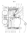
- the rolled strip 6 is withdrawn from a decoiler 31 and via a tape insertion unit 32, which consists of a first Air cushion conveyor 33, a separating knife 34, a second Air cushion conveyor 35 and a roller unit with two in Tape running direction a spaced from each other Deflection rollers 36, 37 and one arranged between them, with a third air cushion conveyor 38 combined tensioning roller 39 exists, promoted in the roll gap 14.
- the Belt insertion unit 32 is on a machine frame 40 arranged in the tape running direction a before and against Belt direction in the direction of arrow d is reversible.
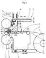
- a positioning device 41 is located on the four-high mill stand 1 for moving two nozzle bars 7, 8 for the lower and the upper work roll 2, 3 and a further nozzle bar 10 for the upper support roller 5 from the maintenance position 7a remote from the roller, 8a, 10a in the operating position 7b, 8b, 10b to the rollers 2, 3, 5 arranged.
- the positioning device 41 consists of two belt inlet side on the two roller stands 42 of the Four-high rolling mill 1 arranged in the vertical direction e, f movable walking beam 43 and two on this in a horizontal Direction g, h movable carriage 44 with cranked Support arms 45, at the lower ends 46, the two nozzle bars 7, 8 for the two work rolls 2, 3 and on the upper one Sections 47 of the nozzle bar 10 and a scraper 48 for the upper backup roller 5 are attached.
- the nozzle bar 9 for the lower support roller 4 is in the Direction of arrow a, d movable machine frame 40 of Ribbon insertion unit 32 arranged.
- pneumatically pilot-operated control valves 12 for the spray nozzles 11 can also be used as electromagnetic valves trained control valves are used.
- the nozzle bars 7-10 are via manifolds 52-54 and a main supply line 55 for the coolant with a Control valve 56 for pressure and quantity control of the coolant a feed pump, not shown, of the coolant circulation system connected.
- a roll cooling and Lubricating device arranged spray nozzles 11 according to FIGS. 8th and 9 are installed as compact units in nozzle assemblies 60, in corresponding openings 61, 62 in that of a roller facing front wall section 59a and the rear Wall portion 59b of the nozzle bar 59 from the rear the same are used against the nozzle bar 59 are sealed and penetrate the interior 63 of the same.
- the spray nozzles 11 are equipped with a nozzle head 64, the in a threaded bore 65 in the one facing a roller front end 66 of the nozzle assembly 60 is screwed in and a Has nozzle opening 67 and a prechamber 68.
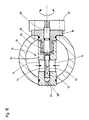
- the spray nozzles 11 are also provided with a rotary slide 69 equipped, the 70 in a central through bore Nozzle assemblies 60 about the longitudinal axis 71-71 of the spray nozzle 11 is rotatably mounted in the bore 70 of the nozzle assembly 60 is sealed and one open to the nozzle head 64 Blind hole 72 and two diametrically opposite Has inlet openings 73 in the region of the blind bore 72, 73 in the open position 11 "of the spray nozzle 11 according to FIG. 9 two corresponding toward the interior 63 of the nozzle bar 59 Cover open inlet openings 74 in the nozzle assembly 60 and in the closed position 11 'of the spray nozzle shown in FIG 11 are closed by the wall 75 of the nozzle assembly 60.
- the nozzle assembly 60 of the spray nozzle 11 is in one piece with this flange 76 formed on the outside of the rear wall portion 59b of the nozzle bar 59 around the Longitudinal axis 71 - 71 of the spray nozzle 11 is rotatably fastened to a limited extent.
- An actuator 77 for actuating the rotary valve 69 of the Spray nozzle 11 is on the mounting flange 76 of the nozzle assembly 60 removed.
- An electric actuator 77 can be used Rotary magnet, a hydraulic cylinder or a pneumatic cylinder be used. There is also the possibility of a Stepper motor for actuating the rotary valve 69 and simultaneous flow control of the coolant and lubricant to use.
- Spray nozzles 11 With a view to keeping the distance as small as possible Spray nozzles 11 across the width 78 of the rolled strip 6 can Actuators 77 for actuating the rotary slide 69 Spray nozzles 11 in the direction of the nozzle axes 71-71 and / or be staggered.
- Nozzle blocks 60 in the nozzle bar 59 for changing the spray pattern to provide the individual spray nozzles, with a rotary drive for each nozzle assembly 60 or a common rotary drive for several Nozzle sticks can be used.
- a spray nozzle 79 with rotary slide 69 is the extended one Nozzle head 64 on the front end 66 of the nozzle assembly 60 screwed on.
- the nozzle head 64 are two diametrical Opposite inlet openings 74 arranged with two Inlet openings 73 in the area of the antechamber 68 of the Nozzle head 64 open blind bore 72 of the rotary valve 69 cooperate in the prechamber 68 of the nozzle head 64 is centered.
Landscapes
- Engineering & Computer Science (AREA)
- Mechanical Engineering (AREA)
- Metal Rolling (AREA)
- Nozzles (AREA)
Abstract
Description
- Fig. 1
- eine perspektivische Darstellung eines Quartowalzgerüstes mit Düsenbalken zum Kühlen und Schmieren der Arbeitswalzen und der Stützwalzen,
- Fig. 2
- eine Vorderansicht der Düsenbalken nach Fig. 1,
- Fig. 3
- eine Schnittdarstellung einer Dreh- und Schiebelagerung eines Endes eines in der Betriebsposition befindlichen Düsenbalkens,
- Fig. 4
- eine Schnittdarstellung einer Dreh- und Schiebelagerung eines Düsenbalkens in der gegenüber der Darstellung in Fig. 3 um 180° gedrehten Wartungsposition,
- Fig. 5
- ein Quartowalzgerüst mit Düsenbalken in der Wartungsposition, einen Abwickelhaspel und Vorrichtungen zum Einführen des Walzbandes in den Walzspalt,
- Fig. 6
- ein Quartowalzgerüst entsprechend Fig. 5 mit Düsenbalken in der Betriebsposition,
- Fig. 7
- die Steuerung der Sprühdüsen bei einem Quartowalzwerk,
- Fig. 8
- eine Längsschnittdarstellung einer mit einem Drehschieber ausgerüsteten Sprühdüse in der Schließstellung,
- Fig. 9
- eine der Fig. 8 entsprechende Darstellung der Sprühdüse in der Offenstellung und
- Fig. 10
- eine abgeänderte Ausführung der Sprühdüse gemäß den Figuren 8 und 9.
Claims (4)
- Walzenkühl- und/oder Schmiervorrichtung für Kaltbandwalzwerke, insbesondere Feinband- und Folienwalzwerke, mit den einzelnen Walzen zugeordneten, an den Seitenschildern der Walzenständern eines oder mehrerer Walzgerüste angebrachten Düsenbalken, in die über die Breite der Walzen Sprühdüsen mit Steuerventilen eingebaut und die relativ zu den ihnen zugeordneten Walzen unabhängig voneinander quer zur Laufrichtung des Walzbandes in zur Bandebene parallelen Ebenen verstellbar sind, zur Regelung der Bandzugspannung über die Bandbreite durch eine Änderung des wirksamen Walzenballendurchmessers und/oder eine Beeinflussung der Walzenschmierung mit einer druck- und/oder mengen- und/oder temperaturgeregelten Zuführung von Walzöl oder Emulsionen, gekennzeichnet durch folgende Merkmale:a) Die Düsenbalken (7, 8) sind mittels eines Linearantriebs (Stellzylinder 26, 27) in Richtung ihrer Längsachse (13 - 13) quer zur Laufrichtung (a) des Walzbandes (6) verschiebbar und mittels eines Drehantriebs (29) um die Längsachse (13-13) schwenkbar.b) An dem Walzgerüst (1) bzw. den Walzgerüsten sind Positioniervorrichtungen (41) zum Verfahren der Düsenbalken (7, 8, 10) aus einer walzenfernen Wartungsposition (7a, 8a, 10a) in die Betriebsposition (7b, 8b, 10b) an die Walzen (2, 3, 5) und aus der Betriebsposition (7b, 8b, 10b) in die Wartungsposition (7a, 8a, 10a) angeordnet.c) Die zu öffnenden oder zu schließenden Steuerventile (12) der Sprühdüsen (11) werden in einer bestimmten Zeit mit einer Zeitverzögerung geschaltet.d) Die mit gleichem Abstand in die Düsenbalken (59) eingebauten Sprühdüsen (11, 79) weisen einen Düsenstock (60) auf, der in entsprechende Öffnungen (61, 62) in dem einer Walze zugewandten vorderen Wandabschnitt (59a) sowie dem rückwärtigen Wandabschnitt (59b) eines Düsenbalkens (59) eingesetzt ist, gegen den Düsenbalken (59) abgedichtet ist und den Innenraum (63) desselben durchsetzt, ferner einen Düsenkopf (64), der in eine Bohrung (65) in dem einer Walze zugewandten vorderen Ende (66) des Düsenstocks (60) eingesetzt, vorzugsweise eingeschraubt ist oder der (64) auf das vordere Ende (66) des Düsenstocks (60) aufgesetzt, vorzugsweise aufgeschraubt ist und mindestens eine Düsenöffnung (67) und eine Vorkammer (68) aufweist, einen Drehschieber (69), der in einer zentrischen Durchgangsbohrung (70) des Düsenstocks (60) um die Längsachse (71-71) der Sprühdüse (11) drehbar gelagert ist und einen zu dem Düsenkopf (64) hin offene Sackbohrung (72) und im Bereich der Sackbohrung (72) mindestens eine Eintrittsöffnung (73) aufweist, die in der Offenstellung (11") der Sprühdüse (11) eine entsprechende, zum Innenraum (63) des Düsenbalkens (59) hin offene Eintrittsöffnung (74) im Düsenstock (60) bzw. Düsenkopf (64) überdeckt und in der Schließstellung (11') der Sprühdüse (11) durch die Wand (75) des Düsenstocks (60) bzw. Düsenkopfs (64) verschlossen ist, sowie ein an dem dem Düsenkopf (64) abgelegenen Ende des Drehschiebers (69) angreifendes Stellglied (77).
- Vorrichtung nach Anspruch 1, gekennzeichnet durch an den beiden Enden (15, 16) der einzelnen Düsenbalken( 7, 8) angebrachte Adapter (17) zur drehbaren und verschiebbaren Lagerung der Düsenbalken (7, 8) um und in Richtung der Balkenlängsachse (13 - 13) auf zwei hohlen Lagerzapfen (18, 19), die in Seitenschilder (20, 21) an den beiden Walzenständern eines Walzgerüstes (1) eingebaut sind, wobei die Zuführung des Kühlmittels bzw. der Emulsionen zu den in den Düsenbalken (7, 8) eingebauten Sprühdüsen (11) und den zugehörigen Steuerventilen (12) durch eine Zuleitung (22) in einem Seitenschild (20) oder beiden Seitenschildern (20, 21), den Hohlraum (23) des in das Seitenschild (20) eingebauten Lagerzapfens (18), den Innenraum (24) des auf dem Lagerzapfen (18) sitzenden Adapters (17) und den Verteilerkanal (25) der Düsenbalken (7, 8) erfolgt, auf den beiden Lagerzapfen (18, 19) der einzelnen Düsenbalken (7, 8) angeordnete Stellzylinder (26, 27) mit an den Adaptern (17) angreifenden Stellkolben (28) zum Verschieben der Düsenbalken (7, 8) quer zur Laufrichtung (a) des Walzbandes (6) sowie einen an einem Adapter (17) der einzelnen Düsenbalken (7, 8) angreifenden Drehantrieb (29) zum Schwenken der Düsenbalken (7, 8) um ihre Längsachse (13 - 13).
- Vorrichtung nach Anspruch 1 und 2 gekennzeichnet durch bandeinlaufseitig an den beiden Walzenständern (42) eines Walzgerüstes (1) angeordnete, in vertikaler Richtung (e, f) verfahrbare Hubbalken (43) sowie auf diesen in horizontaler Richtung (g, h) verfahrbare Schlitten (44) mit Tragarmen (45) für die Düsenbalken (7, 8, 10).
- Vorrichtung nach einem der Ansprüche 1 bis 3, dadurch gekennzeichnet, daß bei einem Quartowalzgerüst (1) an den unteren Enden (46) der Tragarme (45) jeweils mindestens ein Düsenbalken (7, 8) für die untere und die obere Arbeitswalze (2, 3) sowie an den oberen Abschnitten (47) der Tragarme (45) mindestens ein Düsenbalken (10) und ein Abstreifer (48) für die obere Stützwalze (5) befestigt sind.
Applications Claiming Priority (2)
| Application Number | Priority Date | Filing Date | Title |
|---|---|---|---|
| DE20006508U DE20006508U1 (de) | 2000-04-08 | 2000-04-08 | Walzenkühl- und/oder Schmiervorrichtung für Kaltbandwalzwerke, insbesondere Feinband- und Folienwalzwerke |
| DE20006508U | 2000-04-08 |
Publications (3)
| Publication Number | Publication Date |
|---|---|
| EP1142652A2 true EP1142652A2 (de) | 2001-10-10 |
| EP1142652A3 EP1142652A3 (de) | 2004-01-02 |
| EP1142652B1 EP1142652B1 (de) | 2005-08-03 |
Family
ID=7940005
Family Applications (1)
| Application Number | Title | Priority Date | Filing Date |
|---|---|---|---|
| EP01107352A Expired - Lifetime EP1142652B1 (de) | 2000-04-08 | 2001-03-24 | Kaltbandwalzwerk, insbesondere Feinband- und Folienwalzwerk, mit einer Walzenkühl- und/oder Schmiervorrichtung |
Country Status (4)
| Country | Link |
|---|---|
| US (1) | US6450000B2 (de) |
| EP (1) | EP1142652B1 (de) |
| JP (1) | JP2001347307A (de) |
| DE (2) | DE20006508U1 (de) |
Cited By (11)
| Publication number | Priority date | Publication date | Assignee | Title |
|---|---|---|---|---|
| CN103658201A (zh) * | 2013-12-31 | 2014-03-26 | 一重集团大连设计研究院有限公司 | 夹送辊与精轧机间导位导板 |
| CN106311754A (zh) * | 2016-09-14 | 2017-01-11 | 燕山大学 | 适用于冷连轧机组的乳化液流量动态综合优化设定方法 |
| EP3251762A1 (de) | 2016-06-02 | 2017-12-06 | Primetals Technologies Austria GmbH | Schmiervorrichtung zum aufbringen eines schmiermittels beim walzen eines walzgutes |
| CN109892117A (zh) * | 2019-04-02 | 2019-06-18 | 吉林大学 | 一种弹性啮合式秸秆压缩对辊 |
| WO2019241550A1 (en) * | 2018-06-13 | 2019-12-19 | Novelis Inc. | System and method for containing viscous materials in roll processing |
| CN111250549A (zh) * | 2020-01-17 | 2020-06-09 | 一重集团大连工程技术有限公司 | 一种精密板形调控方法及其调控装置 |
| CN111687212A (zh) * | 2020-06-19 | 2020-09-22 | 松阳县景顺实业有限公司 | 一种铜带加工用可逆四辊冷轧切割一体机 |
| US10814365B2 (en) | 2018-06-13 | 2020-10-27 | Novelis Inc. | Systems and methods for cooling a roll in metal processing |
| CN112170481A (zh) * | 2020-09-17 | 2021-01-05 | 邯郸一三高研科技有限公司 | 一种高速钢筋冷轧机 |
| US11007557B2 (en) | 2018-06-13 | 2021-05-18 | Novelis Inc. | Systems and methods for removing viscous materials in metal article processing |
| CN115870870A (zh) * | 2022-12-23 | 2023-03-31 | 一重集团大连工程技术有限公司 | 工作辊在线抛光设备及轧机 |
Families Citing this family (33)
| Publication number | Priority date | Publication date | Assignee | Title |
|---|---|---|---|---|
| US20120255584A1 (en) * | 2004-10-06 | 2012-10-11 | Andreas Gramer | Method of cleaning cylinders or rolls |
| US8347682B2 (en) * | 2004-10-06 | 2013-01-08 | Sms Siemag Aktiengesellschaft | Apparatus for cleaning cylinders or rolls |
| DE102004048619A1 (de) * | 2004-10-06 | 2006-04-13 | Sms Demag Ag | Verfahren und Vorrichtung zum Reinigen von Walzen |
| JP4355280B2 (ja) * | 2004-11-22 | 2009-10-28 | 新日本製鐵株式会社 | 冷間圧延における潤滑油供給方法 |
| DE102008050392A1 (de) | 2008-06-18 | 2009-12-24 | Sms Siemag Aktiengesellschaft | Verfahren und Vorrichtung zum Schmieren von Walzen und eines Walzbandes eines Walzgerüsts |
| DE102009040876A1 (de) | 2008-11-18 | 2010-05-20 | Sms Siemag Ag | Vorrichtung zum Kühlen einer Walze in einem Walzgerüst |
| FR2943943A1 (fr) * | 2009-04-02 | 2010-10-08 | Coriolis Composites | Procede et machine pour l'application d'une bande de fibres sur des surfaces convexes et/ou avec aretes |
| JP2011025305A (ja) * | 2009-07-29 | 2011-02-10 | Nippon Steel Corp | 潤滑油供給方法及び潤滑油供給装置 |
| CH702087A1 (de) * | 2009-10-20 | 2011-04-29 | Bba Innova Ag | Walzenkühlvorrichtung. |
| CN103173793A (zh) * | 2011-12-20 | 2013-06-26 | 西安航天远征流体控制股份有限公司 | 电解铜箔设备水洗喷淋装置 |
| CN102755996B (zh) * | 2012-05-23 | 2014-10-22 | 首钢京唐钢铁联合有限责任公司 | 一种消除平辊工作辊局部磨损的方法 |
| EP2767353A1 (de) * | 2013-02-15 | 2014-08-20 | Siemens VAI Metals Technologies GmbH | Kühlstrecke mit Power Cooling und Laminarkühlung |
| EP2783766A1 (de) * | 2013-03-25 | 2014-10-01 | Siemens VAI Metals Technologies GmbH | Kühlstrecke mit unterem Spritzbalken |
| EP2842646A1 (de) * | 2013-08-29 | 2015-03-04 | Siemens Aktiengesellschaft | Verfahren und Vorrichtung zum Temperieren von Walzen |
| CN103706635B (zh) * | 2013-12-26 | 2016-08-17 | 河南万达铝业有限公司 | 一种铝带热轧系统 |
| CA2934762C (en) | 2013-12-31 | 2018-09-04 | Saint-Gobain Abrasives, Inc. | Coolant delivery system for grinding applications |
| CN104785528B (zh) * | 2015-03-27 | 2016-08-24 | 山东钢铁股份有限公司 | Ucm轧机开辊缝空载窜辊定位方法 |
| CN105327940B (zh) * | 2015-10-27 | 2019-05-17 | 山东钢铁股份有限公司 | 可调式轧辊辊槽冷却装置 |
| CN106269883B (zh) * | 2016-08-31 | 2018-07-03 | 番禺珠江钢管(连云港)有限公司 | 轧辊在机剥落的实时监控系统 |
| EP3308868B1 (de) * | 2016-10-17 | 2022-12-07 | Primetals Technologies Austria GmbH | Kühlung einer walze eines walzgerüsts |
| JP6816482B2 (ja) * | 2016-12-02 | 2021-01-20 | 日本製鉄株式会社 | 圧延油供給設備及び圧延油供給方法 |
| DE102017215851A1 (de) * | 2017-09-08 | 2019-03-14 | Sms Group Gmbh | Walzstraße zum Walzen eines metallischen Guts und Verfahren zum Betreiben einer Walzstraße |
| CN108580558A (zh) * | 2018-04-10 | 2018-09-28 | 燕山大学 | 二次冷轧机组小变形条件下轧辊工艺参数优化设定方法 |
| EP3599036B1 (de) * | 2018-07-26 | 2022-06-15 | Primetals Technologies Austria GmbH | Walzgerüst mit hybrider kühleinrichtung |
| CN112377794B (zh) * | 2020-10-16 | 2022-05-27 | 四川汇源钢建科技股份有限公司 | 一种轧机辊润滑剂喷射结构及其喷射方法 |
| CN115076170B (zh) * | 2022-06-14 | 2024-06-04 | 安徽工业大学 | 一种适用于复合件的高频冲击轧制装置 |
| CN115569991A (zh) * | 2022-09-08 | 2023-01-06 | 一重集团大连工程技术有限公司 | 喷射梁机构、轧机冷却系统及二十辊轧机 |
| CN115488168B (zh) * | 2022-09-26 | 2023-06-20 | 马鞍山延隆新材料科技有限公司 | 一种大压下量高延性冷轧带肋钢筋生产用润滑冷却装置 |
| CN115846112B (zh) * | 2022-12-23 | 2023-08-01 | 佛山市南海区佳朗卫生用品有限公司 | 一种用于纸尿裤的喷胶机构、喷胶复合装置及使用方法 |
| CN116020887B (zh) * | 2023-01-30 | 2025-11-18 | 天津炬坤金属科技有限公司 | 一种食品级包装用冷轧基板轧制液在线吹扫装置 |
| CN116422704A (zh) * | 2023-03-09 | 2023-07-14 | 中国机械总院集团北京机电研究所有限公司 | 喷雾润滑机构及楔横轧系统 |
| CN116078840B (zh) * | 2023-04-10 | 2023-07-07 | 江苏通铜新材料有限公司 | 一种铜带加工生产用冷却系统 |
| CN119926984B (zh) * | 2025-03-20 | 2026-03-03 | 常熟市龙腾特种钢有限公司 | 一种交替冷却的轧钢生产用的脱头辊道结构 |
Family Cites Families (11)
| Publication number | Priority date | Publication date | Assignee | Title |
|---|---|---|---|---|
| US4510784A (en) * | 1983-10-11 | 1985-04-16 | Kaiser Aluminum & Chemical Corporation | Rolling mill spray bar |
| DE3419261C3 (de) * | 1984-05-23 | 1994-12-15 | Achenbach Buschhuetten Gmbh | Walzenkühl- und/oder Schmiervorrichtung für Kaltbandwalzwerke, insbesondere Feinbandwalzwerke |
| GB8514598D0 (en) * | 1985-06-10 | 1985-07-10 | Davy Mckee Poole | Lubrication of rolling mills |
| GB2207373B (en) * | 1985-10-11 | 1991-04-17 | Joseph Donald Svatos | Rolling mill coolant system |
| CH675974A5 (de) * | 1987-10-23 | 1990-11-30 | Lauener Eng Ag | |
| US4912955A (en) * | 1988-12-05 | 1990-04-03 | Norandal Usa Inc. | Spray system for rolling mill |
| US5212975A (en) * | 1991-05-13 | 1993-05-25 | International Rolling Mill Consultants, Inc. | Method and apparatus for cooling rolling mill rolls and flat rolled products |
| US5460023A (en) * | 1991-09-13 | 1995-10-24 | International Rolling Mill Consultants Inc. | Roll surface restoration system and method |
| JPH0615315A (ja) * | 1992-06-30 | 1994-01-25 | Hitachi Ltd | 圧延ロールのヒートクラウン制御装置 |
| DE9418359U1 (de) * | 1994-11-17 | 1995-01-12 | Achenbach Buschhütten GmbH, 57223 Kreuztal | Walzenkühl- und/oder Schmiervorrichtung für Kaltbandwalzwerke, insbesondere Feinbandwalzwerke |
| DE19503544A1 (de) * | 1995-02-03 | 1996-08-08 | Achenbach Buschhuetten Gmbh | Walzenkühl- und/oder Schmiervorrichtung für Kaltbandwalzwerke, insbesondere Feinbandwalzwerke |
-
2000
- 2000-04-08 DE DE20006508U patent/DE20006508U1/de not_active Expired - Lifetime
-
2001
- 2001-03-24 DE DE50106935T patent/DE50106935D1/de not_active Expired - Lifetime
- 2001-03-24 EP EP01107352A patent/EP1142652B1/de not_active Expired - Lifetime
- 2001-04-05 JP JP2001107113A patent/JP2001347307A/ja not_active Withdrawn
- 2001-04-06 US US09/827,704 patent/US6450000B2/en not_active Expired - Lifetime
Cited By (18)
| Publication number | Priority date | Publication date | Assignee | Title |
|---|---|---|---|---|
| CN103658201A (zh) * | 2013-12-31 | 2014-03-26 | 一重集团大连设计研究院有限公司 | 夹送辊与精轧机间导位导板 |
| CN103658201B (zh) * | 2013-12-31 | 2015-08-26 | 一重集团大连设计研究院有限公司 | 夹送辊与精轧机间导位导板 |
| EP3251762A1 (de) | 2016-06-02 | 2017-12-06 | Primetals Technologies Austria GmbH | Schmiervorrichtung zum aufbringen eines schmiermittels beim walzen eines walzgutes |
| WO2017207622A1 (de) | 2016-06-02 | 2017-12-07 | Primetals Technologies Austria GmbH | Schmiervorrichtung zum aufbringen eines schmiermittels beim walzen eines walzgutes |
| US11440067B2 (en) | 2016-06-02 | 2022-09-13 | Primetals Technologies Austria GmbH | Lubricating device for applying a lubricant when rolling a rolling material |
| CN106311754A (zh) * | 2016-09-14 | 2017-01-11 | 燕山大学 | 适用于冷连轧机组的乳化液流量动态综合优化设定方法 |
| RU2730826C1 (ru) * | 2018-06-13 | 2020-08-26 | Новелис Инк. | Устройства и способы удерживания вязких материалов в прокатном производстве |
| WO2019241550A1 (en) * | 2018-06-13 | 2019-12-19 | Novelis Inc. | System and method for containing viscous materials in roll processing |
| JP2020528356A (ja) * | 2018-06-13 | 2020-09-24 | ノベリス・インコーポレイテッドNovelis Inc. | ロール加工において粘性材料を封じ込めるためのシステムおよび方法 |
| US10814365B2 (en) | 2018-06-13 | 2020-10-27 | Novelis Inc. | Systems and methods for cooling a roll in metal processing |
| US10953447B2 (en) | 2018-06-13 | 2021-03-23 | Novelis Inc. | Systems and methods for containing viscous materials in roll processing |
| US11007557B2 (en) | 2018-06-13 | 2021-05-18 | Novelis Inc. | Systems and methods for removing viscous materials in metal article processing |
| CN109892117A (zh) * | 2019-04-02 | 2019-06-18 | 吉林大学 | 一种弹性啮合式秸秆压缩对辊 |
| CN111250549A (zh) * | 2020-01-17 | 2020-06-09 | 一重集团大连工程技术有限公司 | 一种精密板形调控方法及其调控装置 |
| CN111250549B (zh) * | 2020-01-17 | 2021-11-05 | 一重集团大连工程技术有限公司 | 一种精密板形调控方法及其调控装置 |
| CN111687212A (zh) * | 2020-06-19 | 2020-09-22 | 松阳县景顺实业有限公司 | 一种铜带加工用可逆四辊冷轧切割一体机 |
| CN112170481A (zh) * | 2020-09-17 | 2021-01-05 | 邯郸一三高研科技有限公司 | 一种高速钢筋冷轧机 |
| CN115870870A (zh) * | 2022-12-23 | 2023-03-31 | 一重集团大连工程技术有限公司 | 工作辊在线抛光设备及轧机 |
Also Published As
| Publication number | Publication date |
|---|---|
| EP1142652A3 (de) | 2004-01-02 |
| EP1142652B1 (de) | 2005-08-03 |
| DE20006508U1 (de) | 2000-08-31 |
| JP2001347307A (ja) | 2001-12-18 |
| US20010027672A1 (en) | 2001-10-11 |
| DE50106935D1 (de) | 2005-09-08 |
| US6450000B2 (en) | 2002-09-17 |
Similar Documents
| Publication | Publication Date | Title |
|---|---|---|
| EP1142652B1 (de) | Kaltbandwalzwerk, insbesondere Feinband- und Folienwalzwerk, mit einer Walzenkühl- und/oder Schmiervorrichtung | |
| DE10043281B4 (de) | Walzenkühl- und/oder Schmiervorrichtung für Kaltbandwalzwerke, insbesondere Feinband- und Folienwalzwerke | |
| DE3419261C3 (de) | Walzenkühl- und/oder Schmiervorrichtung für Kaltbandwalzwerke, insbesondere Feinbandwalzwerke | |
| DE69224490T2 (de) | Walzwerk, Warmwalzsystem, Walzverfahren und Walzwerknachrüstverfahren | |
| EP0499704B1 (de) | Vorrichtung zum Befetten von Werkstücken in Band- oder Platinenform | |
| DE2922701A1 (de) | Mechanische entzunderungsvorrichtung | |
| EP0623401B1 (de) | Biegeblock zum Biegen der Walzen von Mehrwalzen-Walzgerüsten | |
| DE102012219722A1 (de) | Vorrichtung zum Kühlen von Walzen | |
| DE3616070A1 (de) | Walzenkuehlvorrichtung und -verfahren | |
| DE69303316T2 (de) | Düsenmesser zur Steuerung der Beschichtungsdicke eines Metallüberzugs | |
| EP3150291B1 (de) | Verfahren und vorrichtung zum kühlen einer in einem walzgerüst angeordneten walze | |
| EP1492634B1 (de) | Vorrichtung zum kühlen von walzgut innerhalb der kühlstrecke einer walzanlage | |
| DE3507846C1 (de) | Vorrichtung zum Befetten von Werkstücken bei der spanlosen Umformung und beim Walzen, insbesondere Rollenbandöler | |
| DE19934557C2 (de) | Vorrichtung zum Kühlen von auf einer Förderstrecke geförderten Metallbändern oder -blechen | |
| EP1212153B1 (de) | Walzgerüst | |
| DE69807879T2 (de) | Vorrichtung und verfahren zur beschichtung von tafel- bzw bahnförmigen artikeln | |
| EP0349840A2 (de) | Walzwerk zur Herstellung eines Walzgutes | |
| EP0049425B1 (de) | Verfahren und Anordnung zum Walzen von spannungsfreiem Walzband | |
| EP0054172A2 (de) | Verfahren und Anordnung zum Walzen von spannungsfreiem Walzband | |
| DE69300693T2 (de) | Verfahren und Vorrichtung zum Entfernen von Flüssigkeit von gewalztem Band. | |
| DE19503544A1 (de) | Walzenkühl- und/oder Schmiervorrichtung für Kaltbandwalzwerke, insbesondere Feinbandwalzwerke | |
| DE102008058513B4 (de) | Vorrichtung zum Entfernen von Flüssigkeit von der Oberfläche eines bewegten Bandes und Bandbearbeitungsanlage mit solch einer Vorrichtung | |
| WO2022058152A1 (de) | Verfahren und sprüheinrichtung zur thermischen oberflächenbehandlung eines metallischen produkts | |
| DE3607527A1 (de) | Vorrichtung zum regeln der planheit und dicke von walzband in einem mehrwalzen-bandwalzgeruest | |
| DE60111993T2 (de) | Vorrichtung und Verfahren zum Kühlen von Walzringen |
Legal Events
| Date | Code | Title | Description |
|---|---|---|---|
| PUAI | Public reference made under article 153(3) epc to a published international application that has entered the european phase |
Free format text: ORIGINAL CODE: 0009012 |
|
| AK | Designated contracting states |
Kind code of ref document: A2 Designated state(s): AT BE CH CY DE DK ES FI FR GB GR IE IT LI LU MC NL PT SE TR |
|
| AX | Request for extension of the european patent |
Free format text: AL;LT;LV;MK;RO;SI |
|
| PUAL | Search report despatched |
Free format text: ORIGINAL CODE: 0009013 |
|
| AK | Designated contracting states |
Kind code of ref document: A3 Designated state(s): AT BE CH CY DE DK ES FI FR GB GR IE IT LI LU MC NL PT SE TR |
|
| AX | Request for extension of the european patent |
Extension state: AL LT LV MK RO SI |
|
| 17P | Request for examination filed |
Effective date: 20040325 |
|
| 17Q | First examination report despatched |
Effective date: 20040803 |
|
| AKX | Designation fees paid |
Designated state(s): DE FR GB IT |
|
| GRAP | Despatch of communication of intention to grant a patent |
Free format text: ORIGINAL CODE: EPIDOSNIGR1 |
|
| RTI1 | Title (correction) |
Free format text: COLD STRIP ROLLING MILL, IN PARTICULAR FINE STRIP AND FOIL ROLLING MILL, WITH A ROLL COOLING AND/OR LUBRICATING DEVICE FO |
|
| GRAS | Grant fee paid |
Free format text: ORIGINAL CODE: EPIDOSNIGR3 |
|
| GRAA | (expected) grant |
Free format text: ORIGINAL CODE: 0009210 |
|
| AK | Designated contracting states |
Kind code of ref document: B1 Designated state(s): DE FR GB IT |
|
| REG | Reference to a national code |
Ref country code: GB Ref legal event code: FG4D Free format text: NOT ENGLISH |
|
| GBT | Gb: translation of ep patent filed (gb section 77(6)(a)/1977) |
Effective date: 20050804 |
|
| REF | Corresponds to: |
Ref document number: 50106935 Country of ref document: DE Date of ref document: 20050908 Kind code of ref document: P |
|
| ET | Fr: translation filed | ||
| PLBE | No opposition filed within time limit |
Free format text: ORIGINAL CODE: 0009261 |
|
| STAA | Information on the status of an ep patent application or granted ep patent |
Free format text: STATUS: NO OPPOSITION FILED WITHIN TIME LIMIT |
|
| 26N | No opposition filed |
Effective date: 20060504 |
|
| REG | Reference to a national code |
Ref country code: FR Ref legal event code: PLFP Year of fee payment: 16 |
|
| REG | Reference to a national code |
Ref country code: FR Ref legal event code: PLFP Year of fee payment: 17 |
|
| REG | Reference to a national code |
Ref country code: FR Ref legal event code: PLFP Year of fee payment: 18 |
|
| PGFP | Annual fee paid to national office [announced via postgrant information from national office to epo] |
Ref country code: GB Payment date: 20190325 Year of fee payment: 19 Ref country code: FR Payment date: 20190326 Year of fee payment: 19 Ref country code: IT Payment date: 20190321 Year of fee payment: 19 |
|
| PGFP | Annual fee paid to national office [announced via postgrant information from national office to epo] |
Ref country code: DE Payment date: 20190523 Year of fee payment: 19 |
|
| REG | Reference to a national code |
Ref country code: DE Ref legal event code: R119 Ref document number: 50106935 Country of ref document: DE |
|
| PG25 | Lapsed in a contracting state [announced via postgrant information from national office to epo] |
Ref country code: DE Free format text: LAPSE BECAUSE OF NON-PAYMENT OF DUE FEES Effective date: 20201001 |
|
| GBPC | Gb: european patent ceased through non-payment of renewal fee |
Effective date: 20200324 |
|
| PG25 | Lapsed in a contracting state [announced via postgrant information from national office to epo] |
Ref country code: GB Free format text: LAPSE BECAUSE OF NON-PAYMENT OF DUE FEES Effective date: 20200324 |
|
| PG25 | Lapsed in a contracting state [announced via postgrant information from national office to epo] |
Ref country code: IT Free format text: LAPSE BECAUSE OF NON-PAYMENT OF DUE FEES Effective date: 20200324 |
|
| PG25 | Lapsed in a contracting state [announced via postgrant information from national office to epo] |
Ref country code: FR Free format text: LAPSE BECAUSE OF NON-PAYMENT OF DUE FEES Effective date: 20200331 |