EP1141966B1 - Brennelement für einen siedewasser-kernreaktor - Google Patents
Brennelement für einen siedewasser-kernreaktor Download PDFInfo
- Publication number
- EP1141966B1 EP1141966B1 EP99967945A EP99967945A EP1141966B1 EP 1141966 B1 EP1141966 B1 EP 1141966B1 EP 99967945 A EP99967945 A EP 99967945A EP 99967945 A EP99967945 A EP 99967945A EP 1141966 B1 EP1141966 B1 EP 1141966B1
- Authority
- EP
- European Patent Office
- Prior art keywords
- fuel
- fuel rods
- element according
- fuel element
- spacer elements
- Prior art date
- Legal status (The legal status is an assumption and is not a legal conclusion. Google has not performed a legal analysis and makes no representation as to the accuracy of the status listed.)
- Expired - Lifetime
Links
- 239000000446 fuel Substances 0.000 title claims description 199
- XLYOFNOQVPJJNP-UHFFFAOYSA-N water Substances O XLYOFNOQVPJJNP-UHFFFAOYSA-N 0.000 title claims description 23
- 238000009835 boiling Methods 0.000 title claims description 22
- 125000006850 spacer group Chemical group 0.000 claims description 81
- 239000002826 coolant Substances 0.000 claims description 47
- 239000002184 metal Substances 0.000 claims description 18
- 230000007704 transition Effects 0.000 claims description 14
- 230000035515 penetration Effects 0.000 claims description 5
- 230000007423 decrease Effects 0.000 claims description 4
- 230000003247 decreasing effect Effects 0.000 claims 1
- 239000007788 liquid Substances 0.000 description 10
- 238000000429 assembly Methods 0.000 description 5
- 230000000712 assembly Effects 0.000 description 5
- 238000013461 design Methods 0.000 description 5
- 238000001816 cooling Methods 0.000 description 4
- 239000012071 phase Substances 0.000 description 4
- 239000000498 cooling water Substances 0.000 description 3
- 239000000203 mixture Substances 0.000 description 3
- 239000000523 sample Substances 0.000 description 3
- 230000015572 biosynthetic process Effects 0.000 description 2
- 230000002349 favourable effect Effects 0.000 description 2
- 238000005457 optimization Methods 0.000 description 2
- 230000010355 oscillation Effects 0.000 description 2
- 238000013021 overheating Methods 0.000 description 2
- 238000005204 segregation Methods 0.000 description 2
- 238000010521 absorption reaction Methods 0.000 description 1
- 230000001133 acceleration Effects 0.000 description 1
- 230000006978 adaptation Effects 0.000 description 1
- 230000009286 beneficial effect Effects 0.000 description 1
- 238000005253 cladding Methods 0.000 description 1
- 238000013016 damping Methods 0.000 description 1
- 238000011161 development Methods 0.000 description 1
- 230000018109 developmental process Effects 0.000 description 1
- 230000003292 diminished effect Effects 0.000 description 1
- 238000006073 displacement reaction Methods 0.000 description 1
- 230000000694 effects Effects 0.000 description 1
- 238000001704 evaporation Methods 0.000 description 1
- 230000008020 evaporation Effects 0.000 description 1
- 238000002474 experimental method Methods 0.000 description 1
- 230000004907 flux Effects 0.000 description 1
- 238000010438 heat treatment Methods 0.000 description 1
- 239000007791 liquid phase Substances 0.000 description 1
- 239000000463 material Substances 0.000 description 1
- 238000004904 shortening Methods 0.000 description 1
- 238000012549 training Methods 0.000 description 1
- 238000012546 transfer Methods 0.000 description 1
- 239000012808 vapor phase Substances 0.000 description 1
- 239000011800 void material Substances 0.000 description 1
Images

Classifications
-
- G—PHYSICS
- G21—NUCLEAR PHYSICS; NUCLEAR ENGINEERING
- G21C—NUCLEAR REACTORS
- G21C3/00—Reactor fuel elements and their assemblies; Selection of substances for use as reactor fuel elements
- G21C3/30—Assemblies of a number of fuel elements in the form of a rigid unit
- G21C3/32—Bundles of parallel pin-, rod-, or tube-shaped fuel elements
- G21C3/322—Means to influence the coolant flow through or around the bundles
-
- Y—GENERAL TAGGING OF NEW TECHNOLOGICAL DEVELOPMENTS; GENERAL TAGGING OF CROSS-SECTIONAL TECHNOLOGIES SPANNING OVER SEVERAL SECTIONS OF THE IPC; TECHNICAL SUBJECTS COVERED BY FORMER USPC CROSS-REFERENCE ART COLLECTIONS [XRACs] AND DIGESTS
- Y02—TECHNOLOGIES OR APPLICATIONS FOR MITIGATION OR ADAPTATION AGAINST CLIMATE CHANGE
- Y02E—REDUCTION OF GREENHOUSE GAS [GHG] EMISSIONS, RELATED TO ENERGY GENERATION, TRANSMISSION OR DISTRIBUTION
- Y02E30/00—Energy generation of nuclear origin
- Y02E30/30—Nuclear fission reactors
Definitions
- the invention relates to a fuel assembly, in particular for a Boiling water nuclear reactor, with a bottom and top open Fuel element box as a shell around a plurality of fuel rods, over each other and on the fuel element box Support spacers.
- the maximum Boiling power is the power at which the Steam formation in the fuel element is not yet a reduction the heat released to the coolant leads. Will the maximum boiling transition power exceeded, so it forms on the surface of fuel rods contained in the fuel assembly a vapor film or even a vapor layer, the one Heat transfer resistance represents.
- the generated in the fuel rod Amount of heat then temporarily no longer complete is discharged, the temperature of the fuel rod increases until a new thermal equilibrium sets in This can lead to overheating of the fuel rod and thus too a thermal overload of a fuel rod cladding tube. A Such overheating must be avoided at all costs, because They shorten the life of the fuel rod and thus of the Fuel element would result.
- the flow cross section can be increased by empty positions in the fuel rod grid (EP-B1-0 517 728). For these reasons have been so far Partial fuel rods used while doing the job waived such flags. The resulting empty positions in the upper fuel assembly area also contribute to Improvement of the shutdown behavior.
- the invention therefore provides, in the over the shorter Fuel rods lying area of the boiling water fuel element Arrange flags on the upper edges of the spacer webs and to increase the number of spacers (ie their spacing in proportion to the number of spacers, which results when the spacers at the same distance would be arranged, as in the lower part of the fuel assembly.
- the flags are so inclined in the coolant flow bent along the long fuel rods that flows they impart a swirl to this coolant flow, which causes the liquid water due to the centrifugal force on the fuel rods conducts and keeps the vapor away from the surface. Thereby the water film on the fuel rod surfaces increases, but the bent flags are not that far in the Coolant flow that they are in the room over the shorter fuel rods protrude. The rapid outflow of steam will be so practically not hindered. This leads to the characteristics of the Claim 1.
- the lower ends of all fuel rods are on one level (for example, they are based on one bottom common lower Stabhalteplatte from), however, is a part the fuel rods shortened and ends above spacers, over which advantageously still at least two spacers lie. At most support the non-shortened fuel rods on an upper bar plate from. The distance remains of the bottom and top spacers of each adjacent spacers out of consideration.
- the distances between the spacers of the upper Group B smaller from bottom to top; it can, however, already be advantageous if in the upper group two distances find that from each other and from the constant distance in the lower group are different.
- the fuel rods are in fact transversal vibrations from the coolant flow which are damped by the fact that clamped the fuel rods in the meshes of the spacers are. If this clamping takes place in planes, the constant distance have each other, but then form pronounced natural oscillations with vibrational nodes in these planes out. These natural vibrations are detuned and subdued, if the distances of the spacer planes are different are.
- the position of the spacers is advantageously determined in this way that the top of each shorter fuel rod is practical supported directly in a mesh of a spacer is.
- these natural vibrations especially in the lower range, in which only liquid water flows, and there is the friction of the fuel rods on the bars - with the risk of fuel rod damage - diminished when the fuel rods in the constant intervals the vibration node are clamped.
- the damping of the natural vibration takes place advantageously by different Distance levels in the upper part of the fuel elements, where the flowing water / steam mixture the transverse oscillations does not stimulate so violently.
- the shortened fuel rods end just above distance grids, beneficial in some Fuel rods in the transition region from the lower to upper group.
- Advantageous embodiments of the invention are that the same distances (group A) of the spacer A either 568 mm or 512 mm in size, and that the distances in Remove the top group of spacers from 400 mm to 359 mm.
- the spacers are arranged at right angles to each other, interpenetrating, almost square Mesh-forming metal strips that pass through the Mesh pushed fuel rods in the horizontal direction resilient clamp that in group B next to the penetration points the metal strip at the top edge of sheet metal flags are issued, one vertically through the spacer flowing coolant adjacent to each other Penetration points each swirl pulses around these fürdringungsstellen (preferably opposite each other Swirl impulses) mediate and that at each fürdringungsstelle the metal strip at least two (advantageously four) Sheet metal flags are provided.
- the flags are in particular of molded parts of the Sheet metal strips (spacer webs) formed.
- Fuel elements can also be realized that as Spacer webs hollow cylindrical sleeves with their side walls interconnected, and that the sleeves on carry at their upper end metal flags, one between adjacent Sleeves flowing through coolant a corresponding Impose swirl impulse.
- Fuel assemblies designed in accordance with the invention are very advantageous because they are without compromising safety and with Relatively little effort, the maximum Siedeübergangs antique Increase, without doing impermissible nuclear, thermo-hydraulic or cause mechanical stress.
- Most boiling water fuel assemblies have a square Cross-section of the fuel element box and arranged therein Spacers. It is advantageous in the center of the fuel element (cylindrical or in particular square) Coolant tube arranged, which is also in the upper range of the fuel element liquid cooling water (moderator) leads and therefore increases the density of the moderator there.
- the Fuel rods are in a regular square pattern arranged around the coolant tube, i. the spacers form stitches that have the same shape and size and whose Center points each form the vertices of squares.
- the center of the coolant tube arrangement in the direction of a diagonal of the box section be offset from the center of the box.
- the bundle of fuel rods may also be so be offset diagonally.
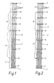
- a fuel assembly according to FIG. 1 contains a multiplicity of fuel rods 4 to 6, which are in vertical operation between a lower bar holding plate 1 and an upper bar holding plate 3 extend.
- the bar holding plates 1 and 3 are with Provided not shown coolant passages.
- the Fuel rods 4 to 6 are arranged parallel to each other and in Spacer 11 to 18 clamped. While the fuel rods normal length not or only loosely on the lower bar holding plates stand up, are the teil Siemens bars with their lower End firmly anchored in the bar plate 1.
- One below and open top fuel box 2 (only in Figures 1 and 3 partially shown) encloses the bundle of fuel rods 4 to 6, forming a closed channel for one the lower rod retaining plate 1 entering liquid coolant.
- the coolant - preferably water - will be on his Path through the fuel assembly 2 through the fuel rods 4 to 6 is heated and begins to evaporate, so that in the upper area of the fuel element is a mixture of liquid and vapor Coolant absorbs the heating power of the fuel rods.
- This mixture of liquid and vapor has a larger volume as the pure liquid.
- To still be undesirable high flow rate at low mass flow rate To avoid, it is known, some of the fuel rods shorten, so that the clear channel cross-section in the upper Area of the fuel element box 2 is greater than in the lower Area.
- the spacers 11 to 18 are design in one lower group A (12 to 15) and into an upper group B (15 divided to 18), wherein the spacings of the spacers 12 to 15 in group A are equal to each other. It can already two rod lengths (full-length and a single part-length) suffice, more advantageous (and expensive) are two Part lengths. Accordingly, the distances of the spacers 15 to 18 in the upper group B smaller than in the lower Group A, especially the smaller, the further up they are are. For more precise adaptation for optimizing the maximum Transition performance required values are the Fuel rods 5 and 6 shortens and ends differently partly over the spacer 14 and the other part directly above that the boundary between the spacer groups A and B representing spacers 15th
- FIG 2 also shows a fuel assembly with 8 spacers 11 to 18, the design in a group A and in a group B are divided. For the sake of clarity Here is the fuel assembly 2 is not shown. To one from the design situation deviating for the arrangement according to FIG. 1 to be fair, here also fuel rods 7 are provided, which are less shortened than the fuel rods 5 and 6th
- FIG 3 and 4 Further variations of inventively designed fuel assemblies show the FIG 3 and 4.
- each 9 spacers 11 to 19 are provided, wherein in 3 as in FIG 1 with three different fuel rod lengths and in FIG. 4 as in FIG. 2 with four different fuel rod lengths is expected.
- FIGS. 1 to 4 each show only one example nine to eleven consecutive fuel rod rows, the all different with fuel rods of different lengths can be equipped.
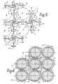
- FIG. 5 shows a greatly enlarged scale one of the spacers 11 to 19, the metal strips crossing at right angles 20 exists, which penetrate each other.
- the metal strips 20 form approximately square meshes for receiving the fuel rods 4 to 7, in the mesh through Nubs 21 and springs 22 are firmly clamped.
- Next to crossing points the metal strip 20 are each upwardly directed, laterally bent metal lugs 23 provided by each arranged next to the same crossing point 25 in the same direction to a parallel to the fuel rods. 4 to 7 flowing through the spacers 11 to 19 partial flow act of the coolant, so that this partial flow 26 a Twist pulse D receives. The rotation caused thereby generates a centrifugal acceleration in the partial flow 26, the liquid phase of the coolant against the fuel rods. 4 throws to 7 and their cooling amplified.
- the flags shown are below the topmost spacer on some (preferably all) spacers Group B, they are missing in group A or are there only much smaller. This will provide the hydraulic stability increased, because compared to the upper part may in the lower Part of the fuel assembly the pressure drop should not be too low. It is also possible for the sake of a low pressure loss in the upper part with one or more spacers (e.g., position 17 in Figures 1 to 4) on springs, nubs or to dispense with similar holding elements for the fuel rods.
- spacers e.g., position 17 in Figures 1 to 4
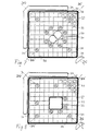
- coolant tube arrangement As a coolant tube arrangement is shown in FIG 7 in Example with two D-shaped tubes 30, 31 and in FIG 8, a single coolant pipe shown with square cross section. In both Cases this coolant tube arrangement covers several Fuel rod positions and located in the center of the fuel assembly no fuel rod.
- a corner of the fuel rod box 33 serves as Guide for a cross-shaped control rod 34, which is diametrically opposite corner is an instrumentation tube 35 for Adjacent probes.
- This arrangement of the probes and control rods in the gaps between the outer surfaces of adjacent Fuel element boxes requires a relatively large width of this water-filled columns, with the control rods leading Columns are often wider than the other columns. This leads to an uneven distribution of absorption material, Moderator and fuel and thus inhomogeneities in neutron flux and the power and burnup of the fuel rods.
- Figures 7 and 8 show some of the fuel rods 36 fuller Length and the webs of the spacers 34, which have corresponding Distance elements 38, 39, which on the outer web of the spacers are arranged, at a predetermined distance from the Inner surfaces of the fuel element box 33 are held.
- the figures 7 and 8 that advantageously already the Whole patterns of arranged around the coolant tube assembly around Fuel rods in the same eccentric arrangement are kept in the box. Accordingly, the spacer elements 38 a wider gap between the outer web of the spacer and the box inner surface before than the spacer elements 39th
- FIG 8 shows that advantageous and the shortened Fuel rods similar eccentric over the fuel assembly cross section are distributed:
- the diagonal DG denotes the direction in the coolant tube assembly and the entire pattern the fuel rods opposite the central axis of the fuel element box are offset.
- the diagonal half of the box section arranged symmetrically around the diagonal DG and the instrumentation tube 35 is adjacent (ie is bounded by the second diagonal DG 'and at least the larger part of the coolant tube arrangement contains) are located more shortened fuel rods PL and PL 'than in the other Half, which is arranged symmetrically around the diagonal DG and adjacent to the control rod 34.
- Figure 8 shows that advantageous in the limited by the diagonal DG 'half the walls of the water channel assembly 32 closer to the adjacent Fuel rods (e.g., PG ') are adjacent as the fuel rods in the other half.
- PL means fuel rods that are less are greatly shortened than the fuel rods PL ', i. the Fuel rods PL 'have the lowest fuel rod length.
Landscapes
- Physics & Mathematics (AREA)
- Engineering & Computer Science (AREA)
- Plasma & Fusion (AREA)
- General Engineering & Computer Science (AREA)
- High Energy & Nuclear Physics (AREA)
- Monitoring And Testing Of Nuclear Reactors (AREA)
- Fuel Cell (AREA)
Applications Claiming Priority (3)
| Application Number | Priority Date | Filing Date | Title |
|---|---|---|---|
| DE19858644 | 1998-12-18 | ||
| DE19858644 | 1998-12-18 | ||
| PCT/EP1999/009983 WO2000038194A1 (de) | 1998-12-18 | 1999-12-15 | Brennelement für einen siedewasser-kernreaktor |
Publications (2)
| Publication Number | Publication Date |
|---|---|
| EP1141966A1 EP1141966A1 (de) | 2001-10-10 |
| EP1141966B1 true EP1141966B1 (de) | 2005-06-01 |
Family
ID=7891688
Family Applications (1)
| Application Number | Title | Priority Date | Filing Date |
|---|---|---|---|
| EP99967945A Expired - Lifetime EP1141966B1 (de) | 1998-12-18 | 1999-12-15 | Brennelement für einen siedewasser-kernreaktor |
Country Status (7)
| Country | Link |
|---|---|
| US (1) | US6600800B2 (enExample) |
| EP (1) | EP1141966B1 (enExample) |
| JP (1) | JP2002533689A (enExample) |
| DE (1) | DE59912127D1 (enExample) |
| ES (1) | ES2243092T3 (enExample) |
| TW (1) | TW445458B (enExample) |
| WO (1) | WO2000038194A1 (enExample) |
Families Citing this family (6)
| Publication number | Priority date | Publication date | Assignee | Title |
|---|---|---|---|---|
| DE10246131A1 (de) | 2002-10-01 | 2004-04-22 | Framatome Anp Gmbh | Brennelement eines Siedewasserreaktors |
| US20050157838A1 (en) * | 2003-12-31 | 2005-07-21 | Lukas Trosman | Axially segregated part-length fuel rods in a reactor fuel bundle |
| US8559586B2 (en) * | 2003-12-31 | 2013-10-15 | Global Nuclear Fuel-Americas, Llc | Distributed clumping of part-length rods for a reactor fuel bundle |
| JP4558477B2 (ja) * | 2004-12-28 | 2010-10-06 | 株式会社グローバル・ニュークリア・フュエル・ジャパン | 沸騰水型原子炉の燃料集合体 |
| JP4573330B2 (ja) * | 2005-08-04 | 2010-11-04 | 原子燃料工業株式会社 | 沸騰水型原子炉用燃料集合体スペーサ及び燃料集合体 |
| RU2646597C1 (ru) * | 2016-09-05 | 2018-03-06 | Российская Федерация, от имени которой выступает Государственная корпорация по атомной энергии "Росатом" - Госкорпорация "Росатом" | Твэл реактора на быстрых нейтронах |
Family Cites Families (36)
| Publication number | Priority date | Publication date | Assignee | Title |
|---|---|---|---|---|
| JPS58223780A (ja) * | 1982-06-23 | 1983-12-26 | 株式会社東芝 | 燃料集合体 |
| JPS6221094A (ja) * | 1985-07-22 | 1987-01-29 | 三菱原子力工業株式会社 | スペクトルシフト用燃料集合体 |
| FR2599177B1 (fr) * | 1986-05-20 | 1991-10-18 | Fragema Framatome & Cogema | Assemblage combustible a grilles anti-corrosion |
| JPS63120292A (ja) * | 1986-11-10 | 1988-05-24 | 株式会社東芝 | 燃料集合体 |
| JPS63149592A (ja) * | 1986-12-12 | 1988-06-22 | 株式会社日立製作所 | 燃料集合体 |
| JP2768673B2 (ja) * | 1987-09-30 | 1998-06-25 | 株式会社東芝 | 燃料集合体 |
| JP2856735B2 (ja) * | 1987-07-20 | 1999-02-10 | 昭二 原 | 無機担体表面の修飾作用を有するシラン化合物とその製造法 |
| JPH01176986A (ja) * | 1988-01-06 | 1989-07-13 | Hitachi Ltd | 燃料集合体 |
| JPH01189591A (ja) * | 1988-01-23 | 1989-07-28 | Nippon Atom Ind Group Co Ltd | 燃料集合体 |
| JPH02192690A (ja) * | 1989-01-20 | 1990-07-30 | Sanyo Electric Co Ltd | 電子レンジ |
| US4957698A (en) * | 1989-02-17 | 1990-09-18 | Advanced Nuclear Fuels Corporation | Advanced boiling water reactor fuel assembly design |
| DE4006264A1 (de) | 1990-02-28 | 1991-08-29 | Siemens Ag | Siedewasserkernreaktor und kernreaktorbrennelement fuer diesen siedewasserkernreaktor |
| DE9117275U1 (de) | 1990-02-28 | 1999-05-27 | Siemens AG, 80333 München | Kernreaktor-Brennelement mit einem tragenden Kühlmittelrohr |
| DE59107094D1 (de) * | 1990-09-18 | 1996-01-25 | Siemens Ag | Brennelement mit gesicherten stabenden am fuss |
| JP2884107B2 (ja) * | 1990-09-27 | 1999-04-19 | 原子燃料工業株式会社 | 燃料集合体 |
| JPH04299283A (ja) * | 1991-03-28 | 1992-10-22 | Toshiba Corp | 原子炉の燃料集合体 |
| US5416812A (en) * | 1991-05-17 | 1995-05-16 | General Electric Company | Optimized critical power in a fuel bundle with part length rods |
| US5174949A (en) * | 1991-05-17 | 1992-12-29 | General Electric Company | Non circular water rod features |
| US5229068A (en) | 1991-05-17 | 1993-07-20 | General Electric Company | Optimized critical power in a fuel bundle with part length rods |
| JP3038266B2 (ja) * | 1991-12-09 | 2000-05-08 | 株式会社東芝 | 燃料スペーサ |
| JPH0694873A (ja) * | 1992-09-16 | 1994-04-08 | Nuclear Fuel Ind Ltd | 燃料集合体 |
| JP2804205B2 (ja) * | 1992-09-18 | 1998-09-24 | 株式会社日立製作所 | 燃料集合体及び炉心 |
| SE505285C2 (sv) * | 1993-06-30 | 1997-07-28 | Asea Atom Ab | Bränslepatron för kokarvattenreaktor, innefattande sju spridare |
| JPH08122474A (ja) * | 1994-10-28 | 1996-05-17 | Toshiba Corp | 燃料スペーサおよび燃料集合体 |
| SE9404497D0 (sv) * | 1994-12-23 | 1994-12-23 | Asea Atom Ab | Bränslepatron med korta bränsleenheter |
| SE504479C2 (sv) * | 1995-06-30 | 1997-02-17 | Asea Atom Ab | Bränslepatron för kokarvattenreaktor |
| JPH09243770A (ja) * | 1996-03-12 | 1997-09-19 | Nuclear Fuel Ind Ltd | 沸騰水型原子炉用燃料集合体 |
| SE506576C3 (sv) * | 1996-05-06 | 1998-02-05 | Asea Atom Ab | Braenslepatron foer en kokarvattenreaktor |
| JPH10142365A (ja) * | 1996-11-14 | 1998-05-29 | Toshiba Corp | 燃料集合体 |
| JPH10260281A (ja) * | 1997-03-19 | 1998-09-29 | Toshiba Corp | 燃料集合体および燃料棒スペーサ |
| US5875224A (en) * | 1997-09-02 | 1999-02-23 | General Electric Company | Swirler attachment for a spacer of a nuclear fuel bundle |
| JP4094092B2 (ja) * | 1997-10-03 | 2008-06-04 | 日立Geニュークリア・エナジー株式会社 | 沸騰水型原子炉用燃料集合体 |
| JP3990013B2 (ja) * | 1997-12-09 | 2007-10-10 | 株式会社日立製作所 | 燃料集合体及び原子炉炉心 |
| JP2931573B2 (ja) * | 1997-12-12 | 1999-08-09 | 株式会社東芝 | 燃料集合体 |
| JP3913386B2 (ja) * | 1998-02-10 | 2007-05-09 | 株式会社日立製作所 | 燃料集合体 |
| JP3788045B2 (ja) * | 1998-07-01 | 2006-06-21 | 株式会社日立製作所 | 燃料集合体 |
-
1999
- 1999-12-15 WO PCT/EP1999/009983 patent/WO2000038194A1/de not_active Ceased
- 1999-12-15 DE DE59912127T patent/DE59912127D1/de not_active Expired - Lifetime
- 1999-12-15 ES ES99967945T patent/ES2243092T3/es not_active Expired - Lifetime
- 1999-12-15 EP EP99967945A patent/EP1141966B1/de not_active Expired - Lifetime
- 1999-12-15 JP JP2000590176A patent/JP2002533689A/ja active Pending
- 1999-12-17 TW TW088122284A patent/TW445458B/zh not_active IP Right Cessation
-
2001
- 2001-06-18 US US09/883,479 patent/US6600800B2/en not_active Expired - Lifetime
Also Published As
| Publication number | Publication date |
|---|---|
| WO2000038194A1 (de) | 2000-06-29 |
| JP2002533689A (ja) | 2002-10-08 |
| TW445458B (en) | 2001-07-11 |
| US6600800B2 (en) | 2003-07-29 |
| DE59912127D1 (de) | 2005-07-07 |
| ES2243092T3 (es) | 2005-11-16 |
| US20020075987A1 (en) | 2002-06-20 |
| EP1141966A1 (de) | 2001-10-10 |
Similar Documents
| Publication | Publication Date | Title |
|---|---|---|
| DE68916570T2 (de) | Siedewasserreaktorkonstruktion mit zweistufiger Reduktion des Druckabfalls. | |
| DE69015020T2 (de) | Siedewasserreaktoranlage mit zweiphasiger Druckabfallreduktion. | |
| EP0517750B1 (de) | Siedewasserkernreaktor und kernreaktorbrennelement für diesen siedewasserkernreaktor | |
| DE69724471T2 (de) | Kerbrennstoffeinheit | |
| DE69508172T2 (de) | Kernbrennstabbündel mit vergrösserter aktiver Höhe für einen Druckwasserreaktor | |
| DE69015848T2 (de) | Halteplatte für Kernbrennstoffelementbündel. | |
| DE3139823C2 (de) | Brennstoffbündel | |
| DE4013397A1 (de) | Brennelementbuendel und distanzhalter dafuer | |
| DE69715620T2 (de) | Kernbrennstabbündel | |
| DE69718316T2 (de) | Kernbrennstoffeinheit | |
| DE69010842T2 (de) | Kernbrennstoffbündel für einen Siedewasserreaktor. | |
| DE69605361T2 (de) | Siedewasserreaktorbrennstabbündel mit variablem Brennstababstand | |
| DE69112124T2 (de) | Rohrbündel für Kernreaktor. | |
| DE69211875T2 (de) | Dampfablassrohr für Siedewasserreaktorbrennelement | |
| EP1141966B1 (de) | Brennelement für einen siedewasser-kernreaktor | |
| DE3811134A1 (de) | Brennelementkasten | |
| DE69717276T2 (de) | Kernbrennstabbündel | |
| DE3203289C2 (enExample) | ||
| DE69208730T2 (de) | Druckverlusterzeugender Abstandshalter in einem Siedewasserreaktorbrennstabbündel mit Teillängenstäben | |
| EP0587608B1 (de) | Brennelement mit einer gitterstruktur zwischen den stäben | |
| DE4432701A1 (de) | Abstandshalter und mit diesem ausgerüstetes Brennelement für einen Siedereaktor | |
| DE4122209A1 (de) | Brennstoffkassette und gitterplatte dafuer | |
| DE69923793T2 (de) | Steuerstab | |
| DE2106342A1 (de) | Brennstoffaggregat für einen Atomreaktor mit parallelen Brennstoffstäben | |
| DE69705614T2 (de) | Brennstabbündel für siedewasserreaktor |
Legal Events
| Date | Code | Title | Description |
|---|---|---|---|
| PUAI | Public reference made under article 153(3) epc to a published international application that has entered the european phase |
Free format text: ORIGINAL CODE: 0009012 |
|
| 17P | Request for examination filed |
Effective date: 20010525 |
|
| AK | Designated contracting states |
Kind code of ref document: A1 Designated state(s): AT BE CH CY DE DK ES FI FR GB GR IE IT LI LU MC NL PT SE |
|
| RBV | Designated contracting states (corrected) |
Designated state(s): DE ES SE |
|
| GRAP | Despatch of communication of intention to grant a patent |
Free format text: ORIGINAL CODE: EPIDOSNIGR1 |
|
| GRAS | Grant fee paid |
Free format text: ORIGINAL CODE: EPIDOSNIGR3 |
|
| GRAA | (expected) grant |
Free format text: ORIGINAL CODE: 0009210 |
|
| AK | Designated contracting states |
Kind code of ref document: B1 Designated state(s): DE ES SE |
|
| REG | Reference to a national code |
Ref country code: IE Ref legal event code: FG4D Free format text: LANGUAGE OF EP DOCUMENT: GERMAN |
|
| REF | Corresponds to: |
Ref document number: 59912127 Country of ref document: DE Date of ref document: 20050707 Kind code of ref document: P |
|
| REG | Reference to a national code |
Ref country code: SE Ref legal event code: TRGR |
|
| REG | Reference to a national code |
Ref country code: ES Ref legal event code: FG2A Ref document number: 2243092 Country of ref document: ES Kind code of ref document: T3 |
|
| PLBE | No opposition filed within time limit |
Free format text: ORIGINAL CODE: 0009261 |
|
| STAA | Information on the status of an ep patent application or granted ep patent |
Free format text: STATUS: NO OPPOSITION FILED WITHIN TIME LIMIT |
|
| 26N | No opposition filed |
Effective date: 20060302 |
|
| REG | Reference to a national code |
Ref country code: DE Ref legal event code: R082 Ref document number: 59912127 Country of ref document: DE Representative=s name: MOERTEL, ALFRED, DIPL.-PHYS. DR.RER.NAT., DE |
|
| REG | Reference to a national code |
Ref country code: DE Ref legal event code: R082 Ref document number: 59912127 Country of ref document: DE Representative=s name: MEISSNER BOLTE PATENTANWAELTE RECHTSANWAELTE P, DE Effective date: 20131112 Ref country code: DE Ref legal event code: R082 Ref document number: 59912127 Country of ref document: DE Representative=s name: MEISSNER BOLTE & PARTNER GBR, DE Effective date: 20131112 Ref country code: DE Ref legal event code: R082 Ref document number: 59912127 Country of ref document: DE Representative=s name: MOERTEL, ALFRED, DIPL.-PHYS. DR.RER.NAT., DE Effective date: 20131112 Ref country code: DE Ref legal event code: R081 Ref document number: 59912127 Country of ref document: DE Owner name: AREVA GMBH, DE Free format text: FORMER OWNER: AREVA NP GMBH, 91052 ERLANGEN, DE Effective date: 20131112 |
|
| REG | Reference to a national code |
Ref country code: DE Ref legal event code: R082 Ref document number: 59912127 Country of ref document: DE Representative=s name: MEISSNER BOLTE PATENTANWAELTE RECHTSANWAELTE P, DE Ref country code: DE Ref legal event code: R082 Ref document number: 59912127 Country of ref document: DE Representative=s name: MEISSNER BOLTE & PARTNER GBR, DE |
|
| REG | Reference to a national code |
Ref country code: DE Ref legal event code: R082 Ref document number: 59912127 Country of ref document: DE Representative=s name: MEISSNER BOLTE PATENTANWAELTE RECHTSANWAELTE P, DE |
|
| PGFP | Annual fee paid to national office [announced via postgrant information from national office to epo] |
Ref country code: SE Payment date: 20171221 Year of fee payment: 19 |
|
| PGFP | Annual fee paid to national office [announced via postgrant information from national office to epo] |
Ref country code: DE Payment date: 20171219 Year of fee payment: 19 Ref country code: ES Payment date: 20180105 Year of fee payment: 19 |
|
| REG | Reference to a national code |
Ref country code: DE Ref legal event code: R119 Ref document number: 59912127 Country of ref document: DE |
|
| REG | Reference to a national code |
Ref country code: SE Ref legal event code: EUG |
|
| PG25 | Lapsed in a contracting state [announced via postgrant information from national office to epo] |
Ref country code: SE Free format text: LAPSE BECAUSE OF NON-PAYMENT OF DUE FEES Effective date: 20181216 |
|
| PG25 | Lapsed in a contracting state [announced via postgrant information from national office to epo] |
Ref country code: DE Free format text: LAPSE BECAUSE OF NON-PAYMENT OF DUE FEES Effective date: 20190702 |
|
| REG | Reference to a national code |
Ref country code: ES Ref legal event code: FD2A Effective date: 20200203 |
|
| PG25 | Lapsed in a contracting state [announced via postgrant information from national office to epo] |
Ref country code: ES Free format text: LAPSE BECAUSE OF NON-PAYMENT OF DUE FEES Effective date: 20181216 |