EP1141529B1 - Zweitaktmotor mit ladungsschichtung - Google Patents
Zweitaktmotor mit ladungsschichtung Download PDFInfo
- Publication number
- EP1141529B1 EP1141529B1 EP00902568A EP00902568A EP1141529B1 EP 1141529 B1 EP1141529 B1 EP 1141529B1 EP 00902568 A EP00902568 A EP 00902568A EP 00902568 A EP00902568 A EP 00902568A EP 1141529 B1 EP1141529 B1 EP 1141529B1
- Authority
- EP
- European Patent Office
- Prior art keywords
- air
- outlet
- crankcase
- combustion chamber
- piston
- Prior art date
- Legal status (The legal status is an assumption and is not a legal conclusion. Google has not performed a legal analysis and makes no representation as to the accuracy of the status listed.)
- Expired - Lifetime
Links
- 238000002485 combustion reaction Methods 0.000 claims description 41
- 239000007789 gas Substances 0.000 claims description 33
- 239000000203 mixture Substances 0.000 claims description 25
- 239000000446 fuel Substances 0.000 claims description 24
- 238000011144 upstream manufacturing Methods 0.000 claims description 7
- 230000002093 peripheral effect Effects 0.000 claims 2
- 238000005422 blasting Methods 0.000 claims 1
- 238000007599 discharging Methods 0.000 claims 1
- 230000002000 scavenging effect Effects 0.000 claims 1
- 238000002360 preparation method Methods 0.000 description 4
- 238000011161 development Methods 0.000 description 3
- 238000013461 design Methods 0.000 description 2
- 238000011010 flushing procedure Methods 0.000 description 2
- 238000012545 processing Methods 0.000 description 2
- 230000009286 beneficial effect Effects 0.000 description 1
- 239000003344 environmental pollutant Substances 0.000 description 1
- 238000004880 explosion Methods 0.000 description 1
- 238000005461 lubrication Methods 0.000 description 1
- 239000012528 membrane Substances 0.000 description 1
- 231100000719 pollutant Toxicity 0.000 description 1
- 230000036316 preload Effects 0.000 description 1
- 230000001681 protective effect Effects 0.000 description 1
- 238000010926 purge Methods 0.000 description 1
- 238000000926 separation method Methods 0.000 description 1
- 238000013517 stratification Methods 0.000 description 1
- 238000012546 transfer Methods 0.000 description 1
Images



Classifications
-
- F—MECHANICAL ENGINEERING; LIGHTING; HEATING; WEAPONS; BLASTING
- F02—COMBUSTION ENGINES; HOT-GAS OR COMBUSTION-PRODUCT ENGINE PLANTS
- F02B—INTERNAL-COMBUSTION PISTON ENGINES; COMBUSTION ENGINES IN GENERAL
- F02B25/00—Engines characterised by using fresh charge for scavenging cylinders
- F02B25/20—Means for reducing the mixing of charge and combustion residues or for preventing escape of fresh charge through outlet ports not provided for in, or of interest apart from, subgroups F02B25/02 - F02B25/18
- F02B25/22—Means for reducing the mixing of charge and combustion residues or for preventing escape of fresh charge through outlet ports not provided for in, or of interest apart from, subgroups F02B25/02 - F02B25/18 by forming air cushion between charge and combustion residues
-
- F—MECHANICAL ENGINEERING; LIGHTING; HEATING; WEAPONS; BLASTING
- F02—COMBUSTION ENGINES; HOT-GAS OR COMBUSTION-PRODUCT ENGINE PLANTS
- F02B—INTERNAL-COMBUSTION PISTON ENGINES; COMBUSTION ENGINES IN GENERAL
- F02B63/00—Adaptations of engines for driving pumps, hand-held tools or electric generators; Portable combinations of engines with engine-driven devices
- F02B63/02—Adaptations of engines for driving pumps, hand-held tools or electric generators; Portable combinations of engines with engine-driven devices for hand-held tools
-
- F—MECHANICAL ENGINEERING; LIGHTING; HEATING; WEAPONS; BLASTING
- F02—COMBUSTION ENGINES; HOT-GAS OR COMBUSTION-PRODUCT ENGINE PLANTS
- F02B—INTERNAL-COMBUSTION PISTON ENGINES; COMBUSTION ENGINES IN GENERAL
- F02B75/00—Other engines
- F02B75/02—Engines characterised by their cycles, e.g. six-stroke
- F02B2075/022—Engines characterised by their cycles, e.g. six-stroke having less than six strokes per cycle
- F02B2075/025—Engines characterised by their cycles, e.g. six-stroke having less than six strokes per cycle two
-
- F—MECHANICAL ENGINEERING; LIGHTING; HEATING; WEAPONS; BLASTING
- F02—COMBUSTION ENGINES; HOT-GAS OR COMBUSTION-PRODUCT ENGINE PLANTS
- F02B—INTERNAL-COMBUSTION PISTON ENGINES; COMBUSTION ENGINES IN GENERAL
- F02B75/00—Other engines
- F02B75/02—Engines characterised by their cycles, e.g. six-stroke
- F02B2075/022—Engines characterised by their cycles, e.g. six-stroke having less than six strokes per cycle
- F02B2075/027—Engines characterised by their cycles, e.g. six-stroke having less than six strokes per cycle four
Definitions
- the invention relates to a two-stroke engine, in particular as a drive motor in a portable, hand-held Tool according to the preamble of claim 1.
- the invention has for its object a two-stroke engine of the generic type in such a way that the flushing losses are reduced with little design effort and thus the exhaust gas quality is improved.
- the essentially fuel-free gas flows near the outlet Area expediently close to the outlet while the necessary for the operation of the internal combustion engine fuel-rich gas expediently supplied via channels remote from the outlet becomes. This allows the fuel-free gas to exit shield like an air curtain, so that the fuel-rich gas cannot flow out through the outlet. It is essential that over the entire duration of the rinse cycle, advantageous over the entire opening time of the outlet Channel, essentially exclusively fuel-free Gas flows in and the fuel / air mixture for operation of the internal combustion engine only via the remote ones Channels overflowed from the crankcase. The above gas outflows are predominantly from the essentially fuel-free gas, which is why good exhaust gas qualities with low HC contents are achieved to let.
- the air supply ducts near the outlet are large, in volume, in particular, several times larger than those far from the outlet, designed the fuel-rich gas supply channels.
- the volume of the air supply channels is constructive provided so large that it covers the whole while volume of air flowing into the combustion chamber be able to record. In this way it will be Gas change from the crankcase into the air supply channel entering fuel / air mixture only as a driving means used to close the air supply outlet Insert the upstream air into the combustion chamber.
- a valve slot-controlled auxiliary window arranged in the cylinder wall, such that it is constantly covered by the piston skirt is.
- the pure air will flow into the area near the outlet and form a curtain shielding the outlet, an outflow of the fuel-rich flowing in far from the outlet Prevents gas.
- the channels close to the outlet are advantageously equipped with a pressure accumulator in connection, which expediently via a of fluctuating crankcase pressure driven diaphragm pump is fed with air.
- a pressure accumulator in connection, which expediently via a of fluctuating crankcase pressure driven diaphragm pump is fed with air.
- the control valve is in particular a pressure-operated one Valve slide, which is in its locked position by a spring is powered.
- the two-stroke engine shown in FIGS. 1 and 2 is in particular as a drive motor in a portable, hand-held Tools such as a motor chain saw, a power cutter, a brush cutter, hedge trimmers, a blower or the like. Can be used advantageously.
- the two-stroke engine 1 consists of a cylinder 2 trained combustion chamber 3, which forms a crankcase 4 is limited by an up and down piston 5.
- the Piston 5 is via a connecting rod 6 with one in the crankcase 4 rotatably mounted crankshaft 7 and drives this.
- the combustion chamber 3 is assigned an outlet 10 through which the Exhaust gases. That for the operation of the internal combustion engine necessary fuel / air mixture is in a mixture preparation device 8, for example one Membrane carburetor, processed and via an inlet duct 9 and an inlet 11 to the crankcase 4.
- the crankcase 4 is - as FIG. 2 shows - with at least two overflow channels 12 connected to the combustion chamber 3.
- opening inlet window 13 of the overflow channels 12 lie relative to one another with respect to an axis of symmetry 14 about diametrically opposite.
- the axis of symmetry 14 divides the outlet channel 10 in plan view of FIG. 2 in two same parts; insofar the axis of symmetry 14 corresponds to Exemplary embodiment also about the longitudinal central axis of the outlet.
- the overflow channels 12 arranged such that one in the direction of the arrow 17 inflowing fuel / air mixture in plan view Fig. 2 at an angle less than or equal to 90 ° Axis of symmetry 14 enters combustion chamber 3. That about the Channels 15 entering in the direction of arrow 18 have one Flow direction, which with the axis of symmetry 14 to the outlet 10 forms an open angle 19 which is smaller than 90 °, in particular about 60 °.
- the combustion chamber 3 thus has four supply gas channels 12 and 15 and an outlet 10. Can also be beneficial more gas supply channels can be provided, where appropriate there should be symmetry with axis 14. That too is Arrangement of a further gas channel between the overflow channels 12 expediently opposite the outlet 10.
- the invention described is for n-channel two-stroke engines can be used advantageously.
- the combustion chamber 3 becomes essentially via the channels 15 near the outlet exclusively fuel-free gas, in particular Air is supplied while via the channels remote from the outlet 12 a rich fuel / air mixture in the combustion chamber 3 occurs.
- the channels 15 are expedient towards the crankcase 4 open, in the area of the combustion chamber end, advantageous near the inlet window 16, an air intake 20 flows into.
- the air intake port opens 20 advantageously via a designed as a check valve Diaphragm valve 21 between the crankcase 4 and the inlet window 16 into the channel 15 near the outlet.
- the Volume of the channels 15 near the outlet is expedient larger, in particular several times larger than the volume of the channels 12 remote from the outlet. that the volume of the duct section of the air supply Channel 15 between its crankcase side End and the confluence of the air intake in the duct 15 about that during a gas change from the channel 15 in the overflow volume of air flowing into the combustion chamber 3 equivalent.
- the volume of the channel section is preferably larger than the overflow volume, thus ensured is that during the entire duration of a gas change, that is the opening time of the inlet window 16 in the essentially only air flows in.
- the piston 5 controls - in a known manner - the inlet 11, the outlet 10 and the inlet windows 13 and 16 of the overflow channels 12 and 15.
- the piston moves upwards 5 are all channels opening into the combustion chamber 3 closed while the inlet 11 of the mixture preparation device 8 open to the crankcase 4 becomes.
- Due to the piston 5 moving upwards Crankcase 4 a negative pressure, which is caused by suction Air / fuel mixture balanced via inlet 11 becomes.
- the channels 15 to the crankcase 4 advantageous are open causes the pending in the crankcase 4 Vacuum at the same time a suction of air over the Air intake 20 and that due to the pressure conditions now open diaphragm valves 21.
- the piston 5 After ignition in the area of top dead center in the combustion chamber 3, the piston 5 is caused by the explosion pressure drive down towards the crankcase 4, whereby - First due to the location of the inlet windows 13 and 16 the outlet 10 is opened and part of the under pressure exhaust gases are discharged. With another downward movement open the piston 5 - in the embodiment at the same time - the inlet windows 13 and 16 of the channels 12 and 15, with the overflow channels 12 exclusively Inflows fuel / air mixture.
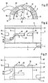
- FIGS. 6 and 7 are a schematic representation of a Partial cylinder processing and the piston 5 of a multi-channel engine shown.
- the combustion chamber 3 of the cylinder 2 has one Outlet 10 and overflow channels 12 and 15 on both sides of the Axis of symmetry 14.
- the inlet channel 9 opens out over the Inlet 11 in the crankcase 4. All in the cylinder wall 44 lying windows are slot controlled by the piston 5.
- an auxiliary window 50 is provided in the cylinder wall 44, the height clearly below the outlet 10 lies.
- the auxiliary window 50 is therefore completely in the Piston travel, that is, the auxiliary window 50 is in any position of the piston 5 covered by the piston skirt 30.
- the auxiliary window 50 lies in the circumferential direction the cylinder wall 44 between the outlet 10 and the overflow channel 15; other layers can also be advantageous his.
- auxiliary window 50 In the piston skirt 30 of the piston 5 is approximately Z-shaped Circumferential groove 31 formed, which extends in the circumferential direction extends over an angle 32 that the circumferentially measured maximum distance of the vertical edges of the outlet window 16 of the air duct 15 and the auxiliary window 50 corresponds (Fig. 5).
- the one close to the outlet Auxiliary window 50 is auxiliary channel 49 4 to 7 formed smaller in volume than the overflow channel 15. This is accordingly Auxiliary window 50 of the auxiliary channel 49 near the outlet is smaller than the entrance window 16 of the overflow duct 15.
- the auxiliary duct 49 is connected to the air intake 20 supplies pure air. The connection is expedient provided that no throttling in the near-outlet channel 15 inflowing air occurs.
- the circumferential groove 31 connects Connection channel in the piston skirt 30 approximately in the upper Dead center OT of the piston 5, the auxiliary air supply window 50 of the auxiliary channel 49 with the entrance window 16 of the the crankcase 4 connected overflow channel near the outlet 15.
- the auxiliary channels 49 are opposite the crankcase 4 closed and can, for example, with a pressure accumulator 24 be connected according to FIG. 8, so that approximately in top dead center OT air through the auxiliary duct 49 and that Auxiliary window 50 enters the circumferential groove 31 and from there via the inlet window 16 into the overflow channel 15 flows.
- the voluminous overflow channel 15 fills thus starting from the combustion chamber 3 towards the crankcase 4 essentially completely with clean air, so that - when the piston 5 towards bottom dead center UT goes down - from the crankcase 4 into the Overflow channel 15 overflowing fuel / air mixture the duct volume is upstream with pure air.
- the connection between the channels 49 and 15 is interrupted and the descending pistons 5 to increase the pressure in the crankcase 4 leads, is also that upstream in the overflow channel 15 Air volume compressed.
- the compressed Air is therefore under pressure in the combustion chamber 3 and displaced the exhaust gases from the combustion chamber 3.
- the Z-shaped connection duct intended for air storage 31 in the piston skirt 30 is designed so that the entry window 16 and 50 over their entire cross section in open the circumferential groove 31, so a throttling at Air transfer from the air intake 20 to the overflow channel 15 is largely avoided.
- the air storage in one from the crankcase 4 to the combustion chamber leading overflow duct 15 is in FIGS. 4 to 7 at Example of a four-channel motor explained.
- the inventive one Thought, towards the combustion chamber 3 pure air in one upstream overflow channel is in the same way for total three, five or more overflow channels applicable, wherein the channels close to the outlet during the entire gas exchange supply clean air to the combustion chamber.
- the Piston 5 a plurality of circumferential grooves 31 to in each to store air near the outlet. Two are useful Circumferential grooves 31 are provided, one each of which a long side of the axis of symmetry 14.
- the auxiliary channel 49 is connected to the Overflow channel 15 at a time in the crankcase Negative pressure is present. Then the crankcase 4 via the overflow duct 15, the connecting duct 31 and the Auxiliary duct 49 clean air sucked in the overflow duct 15 is upstream.
- the air intake is 20 connected to a pressure accumulator 24, the via an advantageously designed as a diaphragm pump 25 Air pump during operation of the internal combustion engine 1 is constantly being charged.
- the diaphragm pump 25 is from fluctuating crankcase pressure driven; the work space 26 of the pump 25 is for this purpose with the crankcase 4 connected.
- the pump chamber 27 is a check valve designed intake valve 28 with an air intake line and via a also designed as a check valve Pressure valve 29 connected to the pressure accumulator 24.
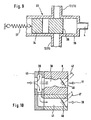
- a valve member 34 is in one Valve housing 35 is provided.
- the valve member 34 is shown in FIG Exemplary embodiment provided as a valve slide, which acts on the front side 36 with the crankcase pressure is.
- the valve member 34 is shown in FIG Locked position under power.
- On the front 36 opposite side is a spring 37 arranged against the force of the valve member 34 in the Release position is displaceable.
- the spring preload is expediently adjustable, the spring 37 one on Tension loaded coil spring can be.
- the mixture preparation device is shown in FIG. 10 in the flow direction before Venturi section 38 arranged an aperture ring 40, the has an inner circumferential groove 39 from which the air line 41 branches.
- the circumferential groove 39 is part-circular in cross section, preferably with a circumferential angle of about 270 ° trained.
- the air line 41 can directly with connected to the air intake 20 of the channels 15 near the outlet become.
- a throttle valve 46 is arranged, which is advantageous via adjusting lever 47 in no closer shown coupled to each other depending on position are.
Landscapes
- Engineering & Computer Science (AREA)
- Chemical & Material Sciences (AREA)
- Combustion & Propulsion (AREA)
- Mechanical Engineering (AREA)
- General Engineering & Computer Science (AREA)
- Cylinder Crankcases Of Internal Combustion Engines (AREA)
- Combustion Methods Of Internal-Combustion Engines (AREA)
- Electrical Control Of Air Or Fuel Supplied To Internal-Combustion Engine (AREA)
Description
- Fig. 1
- einen schematischen Schnitt durch einen bekannten Zweitaktmotor mit vier gaszuführenden Kanälen,
- Fig. 2
- einen Schnitt längs der Linie II-II in Fig. 1,
- Fig. 3
- eine schematische Darstellung der Ladungsschichtung im Brennraum des erfindungsgemäßen Zweitaktmotors,
- Fig. 4
- in schematischer Darstellung eine Ansicht auf einen erfindungsgemäßen Kolben mit einem im Kolbenhemd ausgebildeten Verbindungskanal zur Zuführung von kraftstofffreiem Gas,
- Fig. 5
- einen Teilschnitt durch einen Zylinder für einen Kolben nach Fig. 4,
- Fig. 6
- in schematischer Darstellung eine Teilabwicklung der Zylinderwand nach Fig. 5 mit im oberen Totpunkt stehenden Kolben,
- Fig. 7
- in schematischer Darstellung eine Teilabwicklung der Zylinderwand nach Fig. 5 mit im unteren Totpunkt stehenden Kolben,
- Fig. 8
- in schematischer Darstellung einen erfindungsgemäßen Verbrennungsmotor mit unter Druck zugeführter Luft für die auslaßnahen Kanäle,
- Fig. 9
- eine schematische nicht erfindungsgemäße Darstellung eines Einlaßkanals oder Überströmkanals mit einem im Kanal eingebauten Steuerventil,
- Fig. 10
- in schematischer Darstellung eine Anordnung zum Abzweigen von reiner Luft an einer Gemischaufbereitungseinrichtung.
Claims (8)
- Zweitaktmotor, insbesondere als Antriebsmotor in einem tragbaren, handgeführten Arbeitsgerät wie Motorkettensäge, Trennschleifer, Blasgerät, Freischneidegerät oder dgl., bestehend aus einem in einem Zylinder (2) ausgebildeten Brennraum (3), der von einem auf- und abgehenden Kolben (5) begrenzt ist und der Kolben (5) über ein Pleuel (6) eine in einem Kurbelgehäuse (4) drehbar gelagerte Kurbelwelle (7) antreibt, wobei der Brennraum (3) einen Auslaß (10) zum Abströmen der Abgase aufweist und zur Zufuhr eines von einer Gemischaufbereitungseinrichtung (8) bereitgestellten Kraftstoff/Luft-Gemisches und Verbrennungsluft in den Brennraum (3) mündende gaszuführende Kanäle (12, 15) vorgesehen sind, wobei während der Dauer des Spülzyklus über auslaßnahe Kanäle (15) im wesentlichen ausschließlich Luft zuströmt, und über auslaßferne Kanäle (12) im wesentlichen ausschließlich Kraftstoff/Luft-Gemisch aus dem Kurbelgehäuse (4) überströmt, wobei der luftzuführende Kanal (15) zum Kurbelgehäuse (4) hin offen ist und im Bereich seines brennraumseitigen Endes über ein Ventil (21, 33, 50) mit einem luftzuführenden Luftansaugstutzen (20) verbunden ist,
dadurch gekennzeichnet, daß das Ventil durch ein vom Kolben (5) schlitzgesteuertes Hilfsfenster (50) gebildet ist. - Zweitaktmotor nach Anspruch 1,
dadurch gekennzeichnet, daß der Kanalabschnitt des luftzuführenden Kanals (15) zwischen seinem kurbelgehäuseseitigen Ende und der Einmündung des Luftansaugstutzens (20) in den Kanal (15) ein konstruktives Volumen aufweist, welches etwa dem in einer Gaswechselphase in den Brennraum einströmenden Überströmvolumen entspricht, vorzugsweise größer als das Überströmvolumen ist. - Zweitaktmotor nach Anspruch 1 oder 2,
dadurch gekennzeichnet, daß das aus dem Kurbelgehäuse (4) in den luftzuführenden Kanal (15) eintretende Kraftstoff/Luft-Gemisch lediglich als Schubmittel zum Einbringen der vorgelagerten Luft in den Brennraum (3) dient. - Zweitaktmotor nach einem der Ansprüche 1 bis 3,
dadurch gekennzeichnet, daß das luftzuführende Hilfsfenster (50) im Zylinder (2) angeordnet und in jeder Kolbenstellung vom Kolbenmantels (30) abgedeckt ist, daß im Kolbenmantel (30) zumindest ein Verbindungskanal (31) vorgesehen ist, der in einer vorgegebenen Hubstellung des Kolbens (5) das luftzuführende Hilfsfenster (50) und das Einlaßfenster (16) eines auslaßnahen, luftzuführenden Kanals (15) miteinander verbindet. - Zweitaktmotor nach Anspruch 4,
dadurch gekennzeichnet, daß der Verbindungskanal (31) als zur Zylinderwand (44) offene Umfangsnut (31) ausgebildet ist. - Zweitaktmotor nach einem der Ansprüche 1 bis 5,
dadurch gekennzeichnet, daß der Luftansaugstutzen (20) mit einem Druckspeicher (24) in Verbindung steht. - Zweitaktmotor nach einem der Ansprüche 1 bis 6,
dadurch gekennzeichnet, daß die im auslaßnahen Bereich zugeführte Luft aus einem Druckspeicher (24) zugeführt ist, der vorzugsweise von einer vom schwankenden Kurbelgehäusedruck angetriebenen Membranpumpe (25) gespeist ist. - Zweitaktmotor nach einem der Ansprüche 1 bis 7,
dadurch gekennzeichnet, daß die dem Brennraum (3) auslaßnah zugeführte Luft über einen vor dem Venturi-Abschnitt (38) der Gemischaufbereitungseinrichtung (8) angeordneten Blendenring (40) abgezweigt und über eine Luftleitung (41) aus einer teilkreisförmigen inneren Umfangsnut (39) des Blendenringes (40) abgeführt ist.
Applications Claiming Priority (3)
| Application Number | Priority Date | Filing Date | Title |
|---|---|---|---|
| DE19900445A DE19900445A1 (de) | 1999-01-08 | 1999-01-08 | Zweitaktmotor mit Spülvorlage |
| DE19900445 | 1999-01-08 | ||
| PCT/EP2000/000067 WO2000040843A1 (de) | 1999-01-08 | 2000-01-07 | Zweitaktmotor mit ladungsschichtung |
Publications (2)
| Publication Number | Publication Date |
|---|---|
| EP1141529A1 EP1141529A1 (de) | 2001-10-10 |
| EP1141529B1 true EP1141529B1 (de) | 2003-07-30 |
Family
ID=7893776
Family Applications (1)
| Application Number | Title | Priority Date | Filing Date |
|---|---|---|---|
| EP00902568A Expired - Lifetime EP1141529B1 (de) | 1999-01-08 | 2000-01-07 | Zweitaktmotor mit ladungsschichtung |
Country Status (5)
| Country | Link |
|---|---|
| US (1) | US6571756B1 (de) |
| EP (1) | EP1141529B1 (de) |
| JP (1) | JP2002534630A (de) |
| DE (2) | DE19900445A1 (de) |
| WO (1) | WO2000040843A1 (de) |
Families Citing this family (21)
| Publication number | Priority date | Publication date | Assignee | Title |
|---|---|---|---|---|
| DE10139700B4 (de) | 2000-10-11 | 2013-01-03 | Andreas Stihl Ag & Co. | Verbrennungsmotor als Antriebsmotor in einem tragbaren, handgeführten Arbeitsgerät |
| DE10064719B4 (de) * | 2000-12-22 | 2013-12-12 | Andreas Stihl Ag & Co. | Zweitaktmotor mit Ladungsschichtung |
| DE10104445A1 (de) | 2001-02-01 | 2002-08-08 | Stihl Maschf Andreas | Verbrennungsmotor mit Membranvergaser und einstellbarem CO |
| DE10104446A1 (de) | 2001-02-01 | 2002-08-08 | Stihl Maschf Andreas | Verbrennungsmotor mit einstellbarer CO-Kennlinie |
| ATE289003T1 (de) * | 2001-11-21 | 2005-02-15 | Morini Franco Motori S P A | Verbesserte zweitakt-brennkraftmaschine |
| DE10160539B4 (de) | 2001-12-10 | 2017-06-08 | Andreas Stihl Ag & Co. | Zweitaktmotor mit Spülvorlage und einflutigem Vergaser |
| DE10201967A1 (de) | 2002-01-19 | 2003-07-31 | Stihl Maschf Andreas | Zweitaktmotor mit Spülvorlage |
| DE10223069A1 (de) * | 2002-05-24 | 2003-12-11 | Stihl Maschf Andreas | Zweitaktmotor |
| DE10223070B4 (de) * | 2002-05-24 | 2015-10-08 | Andreas Stihl Ag & Co. | Zweitaktmotor |
| FR2840019B1 (fr) * | 2002-05-24 | 2005-08-19 | Stihl Ag & Co Kg Andreas | Moteur a deux temps, avec piston mobile, a balayage ameliore |
| GB2391263A (en) * | 2002-07-30 | 2004-02-04 | Julian George Daniel Branston | Reciprocating piston engine |
| DE10241213A1 (de) * | 2002-09-06 | 2004-03-18 | Andreas Stihl Ag & Co. | Verfahren zum Betrieb eines Zweitaktmotors mit Gemischansaugung |
| DE10341230B4 (de) * | 2003-09-08 | 2022-10-13 | Andreas Stihl Ag & Co. Kg | Ansaugvorrichtung |
| DE10349641A1 (de) * | 2003-10-24 | 2005-05-19 | Man Nutzfahrzeuge Ag | Motorstaubremsvorrichtung einer 4-Takt-Hubkolbenbrennkraftmaschine |
| US7021252B2 (en) * | 2004-03-04 | 2006-04-04 | Electrolux Home Products, Inc. | Sas piston channel for optimum air scavenging |
| DE102005014575A1 (de) * | 2005-03-31 | 2006-10-05 | Andreas Stihl Ag & Co. Kg | Verbrennungsmotor mit Spülvorlage |
| US7267326B2 (en) * | 2005-05-05 | 2007-09-11 | Tecumseh Products Company | Automatic priming system |
| JP4606966B2 (ja) * | 2005-08-05 | 2011-01-05 | 株式会社やまびこ | 層状掃気2サイクル内燃エンジン |
| JP4309418B2 (ja) * | 2006-10-27 | 2009-08-05 | 株式会社共立 | 2サイクル内燃エンジン |
| US9938926B2 (en) * | 2014-10-07 | 2018-04-10 | Yamabiko Corporation | Air leading-type stratified scavenging two-stroke internal-combustion engine |
| JP6549031B2 (ja) * | 2015-12-21 | 2019-07-24 | 株式会社やまびこ | 空気先導式2ストローク空冷エンジン |
Family Cites Families (13)
| Publication number | Priority date | Publication date | Assignee | Title |
|---|---|---|---|---|
| DE2151941A1 (de) | 1971-10-19 | 1973-04-26 | Blume Geb Schroedet Helga | Gemischspuelung mit spuelvorlage |
| US4000723A (en) * | 1972-08-22 | 1977-01-04 | Performance Industries, Inc. | Engine valve means and porting |
| US4075985A (en) | 1975-06-20 | 1978-02-28 | Yamaha Hatsudoki Kabushiki Kaisha | Two cycle internal combustion engines |
| DE2650834A1 (de) | 1975-12-22 | 1977-06-30 | Thaelmann Fahrzeug Jagdwaffen | Gemischgespuelte zweitakt-brennkraftmaschine |
| GB2022699B (en) | 1978-05-12 | 1982-11-03 | Univ Belfast | Crankcase scavenged twostroke internal combustion engine |
| JPS57183520A (en) * | 1981-05-06 | 1982-11-11 | Isao Oda | Device for preventing mixture from blowing through two-cycle engine |
| US4481911A (en) | 1983-12-29 | 1984-11-13 | Brunswick Corporation | Stratified-charge cross-flow scavenged two-stroke cycle engine |
| JPS6196129A (ja) * | 1984-10-16 | 1986-05-14 | Nippon Clean Engine Res | 2サイクル内燃機関 |
| AT394755B (de) * | 1986-07-08 | 1992-06-25 | Bombardier Rotax Gmbh | Zweitakt-brennkraftmaschine mit einer kurbelkastenspuelung |
| AT397837B (de) | 1988-03-21 | 1994-07-25 | Yamaha Motor Europ | Zweitakt-brennkraftmaschine mit kurbelgehäusespülung |
| DE4219955B4 (de) * | 1992-06-18 | 2007-01-04 | Fa. Andreas Stihl | Zweitaktbrennkraftmaschine für Motorkettensägen |
| US5425346A (en) | 1993-09-14 | 1995-06-20 | Mavinahally; Nagesh S. | Performance improvement design for two-stroke engines |
| JP3024072B2 (ja) | 1996-10-17 | 2000-03-21 | 財団法人石油産業活性化センター | 層状掃気2サイクルエンジン |
-
1999
- 1999-01-08 DE DE19900445A patent/DE19900445A1/de not_active Ceased
-
2000
- 2000-01-07 US US09/889,065 patent/US6571756B1/en not_active Expired - Lifetime
- 2000-01-07 JP JP2000592526A patent/JP2002534630A/ja active Pending
- 2000-01-07 EP EP00902568A patent/EP1141529B1/de not_active Expired - Lifetime
- 2000-01-07 WO PCT/EP2000/000067 patent/WO2000040843A1/de not_active Ceased
- 2000-01-07 DE DE50003096T patent/DE50003096D1/de not_active Expired - Lifetime
Also Published As
| Publication number | Publication date |
|---|---|
| DE50003096D1 (de) | 2003-09-04 |
| WO2000040843A1 (de) | 2000-07-13 |
| EP1141529A1 (de) | 2001-10-10 |
| JP2002534630A (ja) | 2002-10-15 |
| DE19900445A1 (de) | 2000-07-13 |
| US6571756B1 (en) | 2003-06-03 |
Similar Documents
| Publication | Publication Date | Title |
|---|---|---|
| EP1141529A1 (de) | Zweitaktmotor mit ladungsschichtung | |
| DE19860391B4 (de) | Tragbares Arbeitsgerät mit einem Viertaktmotor | |
| DE10197237B4 (de) | Motor mit innerer Verbrennung und Kurbelgehäusespülung | |
| DE69231477T2 (de) | Brennkraftmaschine | |
| EP3284938B1 (de) | Kolben für einen mit spülvorlage arbeitenden zweitaktmotor und zweitaktmotor | |
| DE102007051171A1 (de) | Zweitakt-Verbrennungsmotor | |
| DE10139700B4 (de) | Verbrennungsmotor als Antriebsmotor in einem tragbaren, handgeführten Arbeitsgerät | |
| DE10064719B4 (de) | Zweitaktmotor mit Ladungsschichtung | |
| DE10321571A1 (de) | Zweitaktmotor mit Spülvorlage | |
| DE10241213A1 (de) | Verfahren zum Betrieb eines Zweitaktmotors mit Gemischansaugung | |
| DE102007054929B4 (de) | Handgeführtes Arbeitsgerät | |
| DE10009796B4 (de) | Verbrennungsmotor mit im Luftfiltergehäuse angeordneter Chokeklappe | |
| DE102010045017B4 (de) | Zweitaktmotor | |
| DE3935789A1 (de) | Hubkolben-brennkraftmaschine mit kurbelgehaeuse-ladeluftpumpen | |
| WO2003100229A1 (de) | Zweitaktmotor | |
| DE102006001570B4 (de) | Arbeitsgerät | |
| DE10211404A1 (de) | Tragbares, handgeführtes Arbeitsgerät | |
| DE102010045016B4 (de) | Handgeführtes Arbeitsgerät | |
| DE19618266A1 (de) | Zweitaktmotor mit Spülkanälen | |
| DE10128197A1 (de) | Zweitaktmotor in einem tragbaren, handgeführten Arbeitsgerät | |
| EP3715599B1 (de) | Zweitaktmotor | |
| DE10352808B4 (de) | Zweitaktmotor | |
| DE10319216A1 (de) | Zweitaktmotor | |
| DE102006001567B4 (de) | Arbeitsgerät | |
| DE102024128373B4 (de) | Zweitaktmotor |
Legal Events
| Date | Code | Title | Description |
|---|---|---|---|
| PUAI | Public reference made under article 153(3) epc to a published international application that has entered the european phase |
Free format text: ORIGINAL CODE: 0009012 |
|
| 17P | Request for examination filed |
Effective date: 20010630 |
|
| AK | Designated contracting states |
Kind code of ref document: A1 Designated state(s): AT BE CH CY DE DK ES FI FR GB GR IE IT LI LU MC NL PT SE |
|
| 17Q | First examination report despatched |
Effective date: 20020319 |
|
| GRAH | Despatch of communication of intention to grant a patent |
Free format text: ORIGINAL CODE: EPIDOS IGRA |
|
| GRAH | Despatch of communication of intention to grant a patent |
Free format text: ORIGINAL CODE: EPIDOS IGRA |
|
| GRAA | (expected) grant |
Free format text: ORIGINAL CODE: 0009210 |
|
| AK | Designated contracting states |
Designated state(s): DE FR SE |
|
| REG | Reference to a national code |
Ref country code: IE Ref legal event code: FG4D Free format text: GERMAN |
|
| REF | Corresponds to: |
Ref document number: 50003096 Country of ref document: DE Date of ref document: 20030904 Kind code of ref document: P |
|
| REG | Reference to a national code |
Ref country code: SE Ref legal event code: TRGR |
|
| REG | Reference to a national code |
Ref country code: IE Ref legal event code: FD4D |
|
| ET | Fr: translation filed | ||
| PLBE | No opposition filed within time limit |
Free format text: ORIGINAL CODE: 0009261 |
|
| STAA | Information on the status of an ep patent application or granted ep patent |
Free format text: STATUS: NO OPPOSITION FILED WITHIN TIME LIMIT |
|
| 26N | No opposition filed |
Effective date: 20040504 |
|
| REG | Reference to a national code |
Ref country code: FR Ref legal event code: PLFP Year of fee payment: 17 |
|
| PGFP | Annual fee paid to national office [announced via postgrant information from national office to epo] |
Ref country code: DE Payment date: 20160331 Year of fee payment: 17 |
|
| PGFP | Annual fee paid to national office [announced via postgrant information from national office to epo] |
Ref country code: SE Payment date: 20160129 Year of fee payment: 17 Ref country code: FR Payment date: 20160129 Year of fee payment: 17 |
|
| REG | Reference to a national code |
Ref country code: DE Ref legal event code: R119 Ref document number: 50003096 Country of ref document: DE |
|
| REG | Reference to a national code |
Ref country code: FR Ref legal event code: ST Effective date: 20170929 |
|
| PG25 | Lapsed in a contracting state [announced via postgrant information from national office to epo] |
Ref country code: FR Free format text: LAPSE BECAUSE OF NON-PAYMENT OF DUE FEES Effective date: 20170131 |
|
| PG25 | Lapsed in a contracting state [announced via postgrant information from national office to epo] |
Ref country code: SE Free format text: LAPSE BECAUSE OF NON-PAYMENT OF DUE FEES Effective date: 20170108 Ref country code: DE Free format text: LAPSE BECAUSE OF NON-PAYMENT OF DUE FEES Effective date: 20170801 |