EP1141524B1 - Rollenstössel - Google Patents
Rollenstössel Download PDFInfo
- Publication number
- EP1141524B1 EP1141524B1 EP99963347A EP99963347A EP1141524B1 EP 1141524 B1 EP1141524 B1 EP 1141524B1 EP 99963347 A EP99963347 A EP 99963347A EP 99963347 A EP99963347 A EP 99963347A EP 1141524 B1 EP1141524 B1 EP 1141524B1
- Authority
- EP
- European Patent Office
- Prior art keywords
- roller
- locking ring
- axle
- basic body
- tappet
- Prior art date
- Legal status (The legal status is an assumption and is not a legal conclusion. Google has not performed a legal analysis and makes no representation as to the accuracy of the status listed.)
- Expired - Lifetime
Links
- 238000006073 displacement reaction Methods 0.000 description 2
- 230000001419 dependent effect Effects 0.000 description 1
- 238000011161 development Methods 0.000 description 1
- 230000018109 developmental process Effects 0.000 description 1
Images
Classifications
-
- F—MECHANICAL ENGINEERING; LIGHTING; HEATING; WEAPONS; BLASTING
- F01—MACHINES OR ENGINES IN GENERAL; ENGINE PLANTS IN GENERAL; STEAM ENGINES
- F01L—CYCLICALLY OPERATING VALVES FOR MACHINES OR ENGINES
- F01L1/00—Valve-gear or valve arrangements, e.g. lift-valve gear
- F01L1/12—Transmitting gear between valve drive and valve
- F01L1/14—Tappets; Push rods
-
- F—MECHANICAL ENGINEERING; LIGHTING; HEATING; WEAPONS; BLASTING
- F01—MACHINES OR ENGINES IN GENERAL; ENGINE PLANTS IN GENERAL; STEAM ENGINES
- F01L—CYCLICALLY OPERATING VALVES FOR MACHINES OR ENGINES
- F01L2305/00—Valve arrangements comprising rollers
- F01L2305/02—Mounting of rollers
-
- Y—GENERAL TAGGING OF NEW TECHNOLOGICAL DEVELOPMENTS; GENERAL TAGGING OF CROSS-SECTIONAL TECHNOLOGIES SPANNING OVER SEVERAL SECTIONS OF THE IPC; TECHNICAL SUBJECTS COVERED BY FORMER USPC CROSS-REFERENCE ART COLLECTIONS [XRACs] AND DIGESTS
- Y10—TECHNICAL SUBJECTS COVERED BY FORMER USPC
- Y10T—TECHNICAL SUBJECTS COVERED BY FORMER US CLASSIFICATION
- Y10T74/00—Machine element or mechanism
- Y10T74/21—Elements
- Y10T74/2101—Cams
- Y10T74/2107—Follower
Definitions
- the invention relates to a roller tappet according to the preamble of claim 1.
- roller tappets are z. B. from US 5,385,124 A known.
- the backup of the roller axle takes place there over Retaining rings, which are inside the roller hubs in grooves lie.
- the invention therefore deals with the problem in generic roller tappets the axis on which the role stored in a simple manner in the hub bores too to back up.
- the main body of the plunger may well from two or more interconnected components.
- roller axle according to the invention By securing the roller axle according to the invention with Circlips lying in grooves on the outer diameter the roller tappet are introduced, processing costs saved and it is only one - but larger - circlip needed. Another advantage can be seen in the fact that only one groove stung must become.
- the circlip according to the invention does not have in axial Direction of the pestle are seen lying in a plane that the Longitudinal axis of the roller axis includes, but he can also lie above or below this level. It is sufficient, when the roller axis in a shift in the roller hub starts from the inside against the circlip. By the eccentric position of the locking ring, the length of Roll axis and thus the bearing length increased again become.
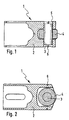
- the roller tappet 1 consists of a base body 2, a Roller axis 3 and a roller 4.
- the main body 2 has Hubs 5, in which the roller axle 3 is mounted.
- On Height of the hub center is in the main body 2 a groove screwed, in which a locking ring 6 is located.
- the Roller axle 3 is freely rotatably mounted in the hubs 5. at an axial displacement of the roller axle 3 in the hubs this runs to the radially inner surface of the locking ring on. The axial displacement of the roller axis 3 is therefore limited by the retaining ring 6.
Landscapes
- Engineering & Computer Science (AREA)
- Mechanical Engineering (AREA)
- General Engineering & Computer Science (AREA)
- Valve-Gear Or Valve Arrangements (AREA)
- Rolling Contact Bearings (AREA)
- Rolls And Other Rotary Bodies (AREA)
Description
- Fig. 1
- einen erfindungsgemäßen Rollenstößel im Querschnitt, geschnitten in Richtung Rollenachse
- Fig. 2
- einen erfindungsgemäßen Rollenstößel im Querschnitt, geschnitten quer zur Rollenachse.
Claims (2)
- Rollenstößel (1) mit einem Grundkörper (2) und einer Rolle (4) und einer im Grundkörper (2) in Naben (5) gelagerten Rollenachse (3), auf der die Rolle (4) drehbar gelagert ist und mit einem Sicherungsring (6) für die Rollenachse (3),
gekennzeichnet durch die Merkmaleder Sicherungsring (6) liegt in einer Nut in einem radial außen liegenden Bereich des Grundkörpers (2),der Sicherungsring (6) liegt in einer Ebene, die etwa senkrecht zur Längsachse des Rollenstößels (1) liegt,die Rollenachse (3) ist drehbar im Grundkörper (2) gelagert,die Länge der Rollenachse (3) sowie die Lage und der Innendurchmesser des Sicherungsrings (6) sind so aufeinander abgestimmt, daß der Sicherungsring (6) ein Austreten der Rollenachse (3) aus den Naben (5) verhindert. - Rollenstößel (1) nach Anspruch 1,
dadurch gekennzeichnet, daß der Sicherungsring (6) auf Höhe der Mittelachse der Rollenachse (3) liegt.
Applications Claiming Priority (3)
| Application Number | Priority Date | Filing Date | Title |
|---|---|---|---|
| DE19857376 | 1998-12-12 | ||
| DE19857376A DE19857376A1 (de) | 1998-12-12 | 1998-12-12 | Rollenstößel |
| PCT/EP1999/009306 WO2000036282A1 (de) | 1998-12-12 | 1999-11-30 | Rollenstössel |
Publications (2)
| Publication Number | Publication Date |
|---|---|
| EP1141524A1 EP1141524A1 (de) | 2001-10-10 |
| EP1141524B1 true EP1141524B1 (de) | 2003-04-02 |
Family
ID=7890859
Family Applications (1)
| Application Number | Title | Priority Date | Filing Date |
|---|---|---|---|
| EP99963347A Expired - Lifetime EP1141524B1 (de) | 1998-12-12 | 1999-11-30 | Rollenstössel |
Country Status (5)
| Country | Link |
|---|---|
| US (1) | US6405698B1 (de) |
| EP (1) | EP1141524B1 (de) |
| BR (1) | BR9916167A (de) |
| DE (2) | DE19857376A1 (de) |
| WO (1) | WO2000036282A1 (de) |
Families Citing this family (16)
| Publication number | Priority date | Publication date | Assignee | Title |
|---|---|---|---|---|
| US7318539B2 (en) * | 2003-04-28 | 2008-01-15 | Power Sprayer Llc | Pump drive unit for battery operated fluid dispensers |
| CN100410526C (zh) * | 2004-01-14 | 2008-08-13 | 博世株式会社 | 燃料供给泵及挺杆结构体 |
| US7497145B2 (en) * | 2005-12-28 | 2009-03-03 | Belvac Production Machinery, Inc. | Preloaded-cam follower arrangement |
| DE102006045933A1 (de) * | 2006-09-28 | 2008-04-03 | Robert Bosch Gmbh | Stößelbaugruppe für eine Hochdruckpumpe und Hochdruckpumpe mit wenigstens einer Stößelbaugruppe |
| DE102007006320A1 (de) | 2007-02-08 | 2008-08-14 | Schaeffler Kg | Mechanischer Rollenstößel für einen Verbrennungsmotor |
| US7568461B1 (en) * | 2008-06-20 | 2009-08-04 | Gm Global Technology Operations, Inc. | Tappet roller end shape for improved lubrication and combination with fuel pump and engine |
| JP2010037997A (ja) * | 2008-08-01 | 2010-02-18 | Denso Corp | 燃料供給ポンプ |
| JP5496696B2 (ja) * | 2010-01-27 | 2014-05-21 | Ntn株式会社 | ポンプ用タペット |
| DE102010019982A1 (de) * | 2010-05-10 | 2011-11-10 | Schaeffler Technologies Gmbh & Co. Kg | Rollenstößel |
| EP2853698B1 (de) | 2013-09-27 | 2016-06-01 | Aktiebolaget SKF | Ventilstössel, Einspritzpumpe und Ventilaktor mit einem solchen Ventilstössel und Herstellungsverfahren |
| EP3002424A1 (de) | 2014-09-30 | 2016-04-06 | Aktiebolaget SKF | Mechanisches System zur Bildung eines Nockenfolgers oder eines Kipphebels |
| US9863382B2 (en) | 2016-05-25 | 2018-01-09 | Hangzhou Xzb Tech Co., Ltd | High pressure oil pump roller tappet |
| US10113584B2 (en) * | 2016-09-30 | 2018-10-30 | Schaeffler Technologies AG & Co. KG | Roller finger follower having a bearing sleeve for a floating axle |
| CN107882607B (zh) * | 2017-12-14 | 2024-03-12 | 杭州新坐标科技股份有限公司 | 一种分体式杯状气门挺柱 |
| CN111749826A (zh) * | 2019-03-26 | 2020-10-09 | 罗伯特·博世有限公司 | 用于高压燃料泵的滚子挺杆 |
| DE112022006078T5 (de) * | 2021-12-21 | 2024-11-14 | Eaton Intelligent Power Limited | Pumpenaktuator mit verbesserter ermüdungslebensdauer |
Family Cites Families (4)
| Publication number | Priority date | Publication date | Assignee | Title |
|---|---|---|---|---|
| DE3618240A1 (de) * | 1986-05-30 | 1987-12-03 | Kloeckner Humboldt Deutz Ag | Hubvorrichtung |
| DE4225363A1 (de) * | 1992-07-31 | 1994-02-03 | Bosch Gmbh Robert | Kraftstoffeinspritzpumpe für Brennkraftmaschinen |
| US5385124A (en) * | 1994-05-31 | 1995-01-31 | Eaton Corporation | Roller follower axle |
| DE19527720A1 (de) * | 1995-07-31 | 1997-02-06 | Woodward Governor Germany Gmbh | Verfahren zur Veränderung des Förderbeginns von Kraftstoffeinspritzpumpen und Kraftstoffeinspritzpumpe |
-
1998
- 1998-12-12 DE DE19857376A patent/DE19857376A1/de not_active Withdrawn
-
1999
- 1999-11-30 WO PCT/EP1999/009306 patent/WO2000036282A1/de not_active Ceased
- 1999-11-30 BR BR9916167-2A patent/BR9916167A/pt not_active IP Right Cessation
- 1999-11-30 US US09/857,919 patent/US6405698B1/en not_active Expired - Lifetime
- 1999-11-30 DE DE59904889T patent/DE59904889D1/de not_active Expired - Lifetime
- 1999-11-30 EP EP99963347A patent/EP1141524B1/de not_active Expired - Lifetime
Also Published As
| Publication number | Publication date |
|---|---|
| BR9916167A (pt) | 2001-09-04 |
| DE59904889D1 (de) | 2003-05-08 |
| US6405698B1 (en) | 2002-06-18 |
| DE19857376A1 (de) | 2000-06-15 |
| EP1141524A1 (de) | 2001-10-10 |
| WO2000036282A1 (de) | 2000-06-22 |
Similar Documents
| Publication | Publication Date | Title |
|---|---|---|
| DE3346661C2 (de) | Sprengring | |
| EP1141524A1 (de) | Rollenstössel | |
| DE10217343A1 (de) | Drehzahlreduktionsgetriebe | |
| DE10333747A1 (de) | Kompakte Differentialgehäusebaugruppe | |
| DE3903676C2 (de) | ||
| DE2602499A1 (de) | Mehrstufige pumpe | |
| DE2648144C2 (de) | Mittenfreie Wälzlager-Drehverbindung | |
| EP1886035B1 (de) | Schrägscheiben-schwenklager | |
| DE2457982A1 (de) | Laufrolle mit auswechselbaren laufringen | |
| DE69203933T2 (de) | Lagerbüchse und Befestigungsschelle für Universalgelenk. | |
| DE4032953A1 (de) | Zweireihiges schraegwaelzlager | |
| EP3984764A1 (de) | Freilaufnabe mit feder aus kunststoff mit zelliger struktur | |
| DE2829792C2 (de) | ||
| DE69411466T2 (de) | Dreharm | |
| DE2808332C2 (de) | ||
| DE19824069A1 (de) | Getriebe | |
| DE2352520C2 (de) | Hydrostatische Kolbenmaschine | |
| DE4314082C2 (de) | Walzenlager für Walzen von Rotationsdruckmaschinen | |
| DE3417056A1 (de) | Spindelantrieb | |
| DE3625800A1 (de) | Rolle, insbesondere radial grosse lauf- oder riemenspannrolle | |
| DE2243138A1 (de) | Radialkolbenpumpe | |
| DE4021989C2 (de) | Mitnehmer für einen Materialförderer | |
| DE3331725C2 (de) | Stirnnockenantrieb insbesondere für Kraftstoffeinspritzpumpen | |
| EP1425519A1 (de) | Lagerung für kreuzgelenkzapfen | |
| DE3704520C2 (de) | Vorrichtung zum Dämpfen von Drehbewegungen |
Legal Events
| Date | Code | Title | Description |
|---|---|---|---|
| PUAI | Public reference made under article 153(3) epc to a published international application that has entered the european phase |
Free format text: ORIGINAL CODE: 0009012 |
|
| 17P | Request for examination filed |
Effective date: 20010525 |
|
| AK | Designated contracting states |
Kind code of ref document: A1 Designated state(s): AT BE CH CY DE DK ES FI FR GB GR IE IT LI LU MC NL PT SE |
|
| GRAG | Despatch of communication of intention to grant |
Free format text: ORIGINAL CODE: EPIDOS AGRA |
|
| 17Q | First examination report despatched |
Effective date: 20020408 |
|
| GRAG | Despatch of communication of intention to grant |
Free format text: ORIGINAL CODE: EPIDOS AGRA |
|
| GRAH | Despatch of communication of intention to grant a patent |
Free format text: ORIGINAL CODE: EPIDOS IGRA |
|
| GRAH | Despatch of communication of intention to grant a patent |
Free format text: ORIGINAL CODE: EPIDOS IGRA |
|
| GRAA | (expected) grant |
Free format text: ORIGINAL CODE: 0009210 |
|
| AK | Designated contracting states |
Designated state(s): DE FR GB IT |
|
| REG | Reference to a national code |
Ref country code: GB Ref legal event code: FG4D Free format text: NOT ENGLISH |
|
| GBT | Gb: translation of ep patent filed (gb section 77(6)(a)/1977) |
Effective date: 20030402 |
|
| REF | Corresponds to: |
Ref document number: 59904889 Country of ref document: DE Date of ref document: 20030508 Kind code of ref document: P |
|
| ET | Fr: translation filed | ||
| PLBE | No opposition filed within time limit |
Free format text: ORIGINAL CODE: 0009261 |
|
| STAA | Information on the status of an ep patent application or granted ep patent |
Free format text: STATUS: NO OPPOSITION FILED WITHIN TIME LIMIT |
|
| 26N | No opposition filed |
Effective date: 20040105 |
|
| PGFP | Annual fee paid to national office [announced via postgrant information from national office to epo] |
Ref country code: GB Payment date: 20141128 Year of fee payment: 16 |
|
| PGFP | Annual fee paid to national office [announced via postgrant information from national office to epo] |
Ref country code: DE Payment date: 20150129 Year of fee payment: 16 |
|
| REG | Reference to a national code |
Ref country code: FR Ref legal event code: PLFP Year of fee payment: 17 |
|
| PGFP | Annual fee paid to national office [announced via postgrant information from national office to epo] |
Ref country code: IT Payment date: 20151124 Year of fee payment: 17 |
|
| REG | Reference to a national code |
Ref country code: DE Ref legal event code: R119 Ref document number: 59904889 Country of ref document: DE |
|
| GBPC | Gb: european patent ceased through non-payment of renewal fee |
Effective date: 20151130 |
|
| PG25 | Lapsed in a contracting state [announced via postgrant information from national office to epo] |
Ref country code: DE Free format text: LAPSE BECAUSE OF NON-PAYMENT OF DUE FEES Effective date: 20160601 Ref country code: GB Free format text: LAPSE BECAUSE OF NON-PAYMENT OF DUE FEES Effective date: 20151130 |
|
| REG | Reference to a national code |
Ref country code: FR Ref legal event code: PLFP Year of fee payment: 18 |
|
| PG25 | Lapsed in a contracting state [announced via postgrant information from national office to epo] |
Ref country code: IT Free format text: LAPSE BECAUSE OF NON-PAYMENT OF DUE FEES Effective date: 20161130 |
|
| REG | Reference to a national code |
Ref country code: FR Ref legal event code: PLFP Year of fee payment: 19 |
|
| PGFP | Annual fee paid to national office [announced via postgrant information from national office to epo] |
Ref country code: FR Payment date: 20181129 Year of fee payment: 20 |