EP1139543A1 - Verbindungsanordnung für die Anschlüsse eines Elektromotors - Google Patents
Verbindungsanordnung für die Anschlüsse eines Elektromotors Download PDFInfo
- Publication number
- EP1139543A1 EP1139543A1 EP01106866A EP01106866A EP1139543A1 EP 1139543 A1 EP1139543 A1 EP 1139543A1 EP 01106866 A EP01106866 A EP 01106866A EP 01106866 A EP01106866 A EP 01106866A EP 1139543 A1 EP1139543 A1 EP 1139543A1
- Authority
- EP
- European Patent Office
- Prior art keywords
- section
- magnet wire
- terminal
- external connection
- wing
- Prior art date
- Legal status (The legal status is an assumption and is not a legal conclusion. Google has not performed a legal analysis and makes no representation as to the accuracy of the status listed.)
- Granted
Links
Images


Classifications
-
- H—ELECTRICITY
- H02—GENERATION; CONVERSION OR DISTRIBUTION OF ELECTRIC POWER
- H02K—DYNAMO-ELECTRIC MACHINES
- H02K3/00—Details of windings
- H02K3/46—Fastening of windings on the stator or rotor structure
- H02K3/52—Fastening salient pole windings or connections thereto
- H02K3/521—Fastening salient pole windings or connections thereto applicable to stators only
- H02K3/525—Annular coils, e.g. for cores of the claw-pole type
-
- H—ELECTRICITY
- H02—GENERATION; CONVERSION OR DISTRIBUTION OF ELECTRIC POWER
- H02K—DYNAMO-ELECTRIC MACHINES
- H02K15/00—Methods or apparatus specially adapted for manufacturing, assembling, maintaining or repairing of dynamo-electric machines
- H02K15/0056—Manufacturing winding connections
-
- H—ELECTRICITY
- H02—GENERATION; CONVERSION OR DISTRIBUTION OF ELECTRIC POWER
- H02K—DYNAMO-ELECTRIC MACHINES
- H02K15/00—Methods or apparatus specially adapted for manufacturing, assembling, maintaining or repairing of dynamo-electric machines
- H02K15/0056—Manufacturing winding connections
- H02K15/0068—Connecting winding sections; Forming leads; Connecting leads to terminals
-
- H—ELECTRICITY
- H02—GENERATION; CONVERSION OR DISTRIBUTION OF ELECTRIC POWER
- H02K—DYNAMO-ELECTRIC MACHINES
- H02K5/00—Casings; Enclosures; Supports
- H02K5/04—Casings or enclosures characterised by the shape, form or construction thereof
- H02K5/22—Auxiliary parts of casings not covered by groups H02K5/06-H02K5/20, e.g. shaped to form connection boxes or terminal boxes
- H02K5/225—Terminal boxes or connection arrangements
Definitions
- the present invention relates to a terminal structure employed in an inner rotor-type motor, and more particularly, to a terminal structure of a motor suitable for connection by welding.
- solder for welding or attaching various kinds of parts is desired to be lead-free. Accordingly, research on lead-free solder (solder containing no lead) has been actively carried out. Use of lead-free solder also for connecting ends of a magnet wire of a motor coil is being considered.
- a PM-type stepping motor after a an end part of a magnet wire from a coil is bound several turns around a terminal press-fitted into a terminal block (bobbin), the terminal is dipped in a solder bath filled with molten solder to detach an insulation coating from the magnet wire and at the same time to connect a copper lead wire as a core wire and the terminal by means of soldering, wherein the above mentioned lead-free solder is expected to be used.
- the lead-free solder is expected to be used in the connection of the end of magnet wire of the PM-type stepping motor, the molten lead-free solder suffers an intense oxidization and becomes brittle (so-called cold solder) unless placed in a reduced atmosphere of nitrogen. Thus, its reliability cannot be ensured and the lead-free solder has not been adopted.
- the lead-free solder from the viewpoint of its characteristics, is subject to various restrictions such as a method of use and its solderability with objects to be soldered, and further, compared with a conventional eutectic-type solder, has a higher melting point, is more liable to cause a problem like a poor contact, requires a higher level of soldering technique, is more difficult to use, and is more expensive as well. So, an alternative to the lead-free solder has been under consideration.
- the present invention has been made in view of the above-mentioned circumstances, and therefore has an object to provide a motor terminal having a structure which enables a coil and an external circuit to be connected securely and with a good workability, while saving material resources and increasing safety relating to environmental pollution.
- a terminal structure for a motor which comprises a stator in which a coil formed by winding a magnet wire around a bobbin made of an insulating material is inserted in a stator yoke made of a soft magnetic material and a rotor which includes a permanent magnet rotatably arranged in an inner circumference of the stator, the terminal structure characterized in that the bobbin includes a terminal for connecting the coil and an external circuit and that the terminal consists integrally of a magnet wire binding section to connect to the magnet wire of the coil, an external connection section to connect to the external circuit and a support base section to press-fit into a terminal block (bobbin) and hold the terminal onto the block.
- the terminal is structured into three sections by function.
- the first is the magnet wire binding section that does a function of a terminal to connect to the magnet wire from the coil wound around the bobbin
- the second is the external connection section that has a function of a terminal to connect to the external circuit
- the third is the support base section that press-fits into the terminal block and hold the terminal onto the block. While these three sections are adapted to be handled independently of each other, they are structured integrally so as to be handled as a single terminal.
- the reason for employing the structure of the terminal composed of three sections is as follows.
- an end of magnet wire that is, connecting, by means of fusing (plasma welding), the magnet wire bound around the magnet wire binding section to the terminal
- a discharge current resulting from plasma welding must be allowed to flow, and therefore a ground electrode of a plasma welding machine is connected to the external connection section which is electrically continuous with a welded portion, thereby enabling the welding operation and also enabling the terminal to connect externally without getting melted or deformed by the welding.
- the terminal may be so structured that a direction and position of the terminal may be settled by press-fitting a junction of the magnet wire binding section, the external connection section and the support base section, together with the support base section, into a guide hole and a groove provided in the terminal block.
- the length of the external connection section is greater than the length of the magnet wire binding section.
- the reason the length of the external connection section is set greater than that of the magnet wire bending section is, to make the connection of the ground electrode easier when connecting the magnet wire from the coil onto the magnet wire binding section by plasma welding, and make the external connection of the terminal easier.
- the length of the external connection section may be set equivalent to the length of the magnet wire binding section.
- connection of the magnet wire binding section and the magnet wire of the coil is carried out by means of fusing.
- connection of the magnet wire binding section and the magnet wire of the coil is carried out by resistance welding.
- the support base section and the external connection section are both formed in a rectangular shape and connected to each other in series longitudinally
- the magnet wire binding section is formed in a substantially L-shape with a first wing thereof joining with the junction of the support base section and the external connection section in such a manner that the first wing is perpendicular to the support base section and that a second wing thereof is parallel with the external connection section with a given distance therebetween, and the length of the second wing is set different from that of the external connection section.
- an end portion of magnet wire of the coil is bound around the second wing of the magnet wire binding section and the length of the second wing is set so that the distance from an end of the binding of the magnet wire to a tip end of the second wing falls within a range of 0.5 to 3 mm.
- the support base section and the external connection section are both formed in a rectangular shape and connected to each other in series longitudinally
- the magnet wire binding section is formed in a substantially L-shape with a first wing thereof joining with the conjunction of the support base section and the external connection section in such a manner that the first wing is perpendicular to the support base section and that a second wing thereof is parallel with the external connection section with a given distance therebetween
- the length of the external connection section is set larger than the length of the second wing
- the junction of the support base section, the external connection section and the first wing of the magnet wire binding section, as well as the support base section is adapted to press-fit into the terminal block (bobbin).
- the tip end of magnet wire of the coil is bound around the second wing of the magnet wire binding section, and the length of the second wing is set so that the distance from an end of the binding of the magnet wire to a tip end of the second wing falls within a range of 0.5 to 3 mm.
- a lead terminal for bridging the external connection section and the external circuit is connected to the external connection section by resistance welding.
- a groove into which the lead terminal fits is provided at the tip end of the external connection section.
- the lead terminal is set wider at an end joining with the external connection section, and a groove is provided at the center of the wider portion for fixing the external connection section.
- a PM-type stepping motor (inner rotor-type stepping motor) 1 includes stator yokes 2, 3, which are made of steel of a soft magnetic material and pressed to be formed in a donut-shape. On an inner circumference of the stator yokes 2, 3, pole teeth shaped like a comb (not shown) are provided.
- the stator yokes 2, 3 encase a coil 6, which is formed by winding a magnet wire 4 around a bobbin 5, and constitute a stator assembly 7 in association with the coil 6.
- Two stator assemblies 7, 7 are put together with one on another as shown in Fig. 1. There are provided two bobbins 5, 5 to mate the two stator assemblies 7, 7, respectively.
- a front plate 8 and a rear plate 9 are fixed onto the stator assemblies 7, 7 in such a manner as to cover a space defined by the inner circumference of the stator yokes 2, 3.
- a rotor 10 is provided inside the stator assemblies 7, 7.
- the rotor 10 includes a shaft 11 as a rotation axis and a permanent magnet 12 having a plurality of magnetic poles on the circumference thereof opposite to the comb-like pole teeth formed on the inner circumference of the stator yokes 2, 3.
- the shaft 11 is press-fitted into a sleeve 13.
- the permanent magnet 12 and the sleeve 13 (meaning also shaft 11) are fixedly held together with a holder 14 made of a high polymer material.
- the rear plate 9 is molded with PBT resin, a kind of high polymer, integrally with the two stator assemblies 7, 7 put together back to back.
- a hole 15 for bearing as an axis of rotation and a diameter of the inner circumference of the stator assemblies 7, 7, where the comb-like pole teeth are provided, are simultaneously formed with a same mandrel. Accordingly, its highly-precise coaxiality can be ensured.
- the bobbin 5 is made of a high polymer material such as the PBT resin.
- the bobbin 5 generally comprises, as shown in Figs. 4 and 5, a cylinder 16 and approximately annular flanges 17, 17 provided at both ends of the cylinder 16 and projecting radially outward.
- One flange 17 (lower side in Fig. 4) of the two flanges 17, 17 includes an approximately annular flange proper 18 and a terminal block 19 formed on a portion (near a terminal 23 to be described later) of the flange proper 18 and substantially rectangular in a plan view (See Fig. 5).
- the terminal block 19 projects outward in a radial direction from the flange proper 18 and is set larger in thickness than the flange proper 18. As described above, two bobbins 5 are provided, and hence two terminal blocks 19 are provided. The two terminal blocks 19 are put together, as shown in Figs. 1 and 3.
- Two terminals 23 made of phosphorous bronze and consisting integrally of a magnet wire binding section 20, an external connection section 21 and a support base section 22 are press-fitted into the terminal block 19 of the bobbin 5.
- the motor 1 is adapted to include 4 terminals 23, as shown in Fig. 3, as the motor has two bobbins 5 each including two terminals 23.
- a lead terminal 24 connecting to an external circuit is connected to each of the four terminals 23.
- Four lead terminals 24 go through a lead terminal holder 25 which projects from the front plate 8.
- the rearward projection lengths of the four lead terminals 24 from the lead terminal holder 25 are determined to the positions of the terminals 23 to be connected to.
- the magnet wire binding section 20 of the terminal 23, around which the magnet wire 4 of the coil 6 is bound several turns, is plasma welded for connection with the magnet wire 4 and for holding the same, to thereby improve the reliability of winding and the workability of handling.
- the external connection section 21 fits into a groove 26 (See Fig. 7) provided on a tip end of the lead terminal 24 to connect externally with a tip end thereof projecting from the lead terminal 24, is crimped with the lead terminal 24 and plasma-welded for connection.
- the support base section 22 is adapted to fit into a hole 27 and a groove 28 continuous therewith which are formed in the terminal block 19 of the bobbin 5, thereby supporting the terminal 23 onto the terminal block of the bobbin 5 precisely.
- the support base section 22 and the external connection section 21 are both formed in a rectangle shape, and join with each other in series (the portion is referred to as junction 29 "joining portion").
- the magnet wire binding section 20 is formed in an approximately L shape.
- One wing (first wing 20a) of the magnet wire binding section 20 joins with the junction 29 in such a manner that the first wing 20a is perpendicular to the support base section 22 and that other wing (second wing 20b) of the magnet wire binding section 20 is parallel with the external connection section 21 with a given distance therebetween.
- the length of the external connection section 21 is set larger than that of the second wing 20b of the magnet wire binding section 20 as shown in Figs. 5 and 6.
- the magnet wire 4 of the coil 6 (end of the coil 6) is bound (referred to as binding 30) several turns around the second wing 20b of the magnet wire binding section 20 upon winding.
- the length of the magnet wire of the coil 6 is set so that the distance H from the end of the binding 30 of the magnet wire 4 to the tip end of the second wing 20b falls within a range of 0.5 to 3 mm.
- the fusing connection is carried out as follows. First, the second wing 20b of the magnet wire binding section 20 is melted, and an insulating coating on the magnet wire 4 of the coil 6 is thermally peeled off with this molten metal, whereby a copper wire as a core wire is connected to the second wing 20b. If the distance between the tip end of the second wing 20b and the end of the binding 30 is too short or zero, the magnet wire 4 of the coil 6 is sublimed due to the energy of plasma (arc), and the connection is prohibited. In order to avoid this problem (failure of connection), the above-mentioned distance H is set 0.5 mm or longer.
- the distance H is set longer than 3 mm, the molten metal does not reach the magnet wire 4 of the coil 6, and thus the connection does not happen. To avoid this problem, the distance H is set 3 mm maximum.
- a widened portion 31 is formed at the end of the lead terminal 24, as shown in Fig. 7, and at the center of the widened portion 31 the groove 26 is provided for receiving the external connection section 21.
- the external connection section 21 fits into the groove 26 with its tip end projecting, is crimped with the terminal 23 and connected to the lead terminal 24 by plasma welding.
- the lead terminal 24 is grounded at the time of welding.
- the magnet wire 4 of the coil 6 is connected to the external circuit through the terminal 23 press-fitted into the terminal block 19 and the lead terminal 24.
- this PM-type stepping motor 1 the two stator assemblies 7, 7 are joined to each other back to back, and the stator formed by this joining is molded integrally with the rear plate 9 using a PBT resin (a polymer material).
- a PBT resin a polymer material
- the hole 15 for bearing as a rotation axis and the comb-like pole teeth provided on the inner circumference of the stator assemblies 7, 7 are formed simultaneously using a unitary type of mandrel.
- this PM-type stepping motor 1 guarantees a highly-precise coaxiality.
- the terminal 23 consists integrally of the magnet wire binding section 20 to connect to the magnet wire 4 of the coil 6, the external connection section 21 to connect to the external circuit, and the support base section 22 to press-fit into the terminal block 19, wherein the magnet wire 4 is plasma welded for connection through to the external connection section 21 (terminal 23), thereby carrying out the connection of the terminal of the motor 1 by means of welding (plasma welding) .
- welding plasma welding
- the lead terminal 24 and the external connection section 21 are brought into secure and stable contact. As a result, plasma welding is carried out stably. Further, since the external connection section 21 fits into the groove 26 of the lead terminal 24 whereby the external connection section 21 and the lead terminal 24 contact with each other securely and stably, an electrical continuity is ensured. In this case, after the end of the external connection section 21 fits into the groove 26 of the lead terminal 24, the tip end is crimped with the lead terminal 24. Thus the contact between the external connection section 21 and the lead terminal 24 is further secured, resulting in an improvement in its electrical continuity.
- the terminal of the motor 1 is connected by welding (plasma welding), and therefore the reduction in the workability of connecting the terminal of the motor 1 and the cost increase for the apparatus due to lead-free soldering can be avoided.
- the insulation coating of the magnet wire 4 can be peeled off effectively.
- the terminal 23 consists integrally of the magnet wire binding section 20, the external connection section 21 and the support base section 22 and since the support base section 22 press-fits into the hole 27 of the terminal block 19 (outer surface of the bobbin 5), the direction and position of the terminal 23 are settled securely, to thereby increase the stability.
- the support base section 22 fits into the hole 27 and at the same time the first wing 20a of the magnet wire binding section 20, as well as the junction 29, fits into the groove 28 thereby press-fitting the terminal 23 into the terminal block 19, so the direction and position of the terminal 23 can be settled further securely and stably.
- the distance H from the end of the binding 30 to the tip end of the second wing 20b of the magnet wire binding section 20 is set to fall within a range of 0.5 to 3 mm, it can be prevented from happening that the magnet wire 4 of the coil 6 is sublimed due to the energy of plasma (arc) and that the molten metal does not reach the magnet wire 4, leading to a failure in connection. Thus, good welding is ensured.
- the length of the external connection section 21 is set larger than that of the second wing 20b of the magnet wire binding section 20. Therefore, the external connection section 21 can be connected to the lead terminal 24 easier, and the interference thereof can be reduced to a minimum allowing the external connection section 21 to be bent at a right angle, for instance. To that extent, usage is expanded for flexible application.
- the external connection section 21 is bent as mentioned above, it may arise that the terminal 23 is too long, resulting in deterioration in the workability. In such a case, the terminal 23 is connected to the lead terminal 24 while holding the terminal 23, for instance, on a flange provided separately for stabilization, whereby the deterioration of the workability can be prevented.
- the terminal 23 is not limited to the above embodiment, but a terminal 23A (second embodiment) shown in Fig. 8, a terminal 23B (third embodiment) shown in Fig. 9 and a terminal 23C (fourth embodiment) shown in Fig. 10 may be used.
- the support base section 22 of the terminal 23A is provided with a wedge-like projection 40 that prevents the terminal 23A from pulling out from the terminal block 19, and the hole 27 in the terminal block 19 (outer surface of the bobbin 5) is provided with an engaging portion (not shown) to catch the projection 40.
- the pulling-out strength of the terminal 23A is increased due to the projection 40 being caught by the engaging portion (not shown) .
- the terminal 23A is held securely.
- a recess instead of the projection 40 may be formed at the support base section 22, and a projection as an engaging portion for the engagement with the recess may be provided on the wall of the hole 27 in the terminal block 19. Further, both a projection and a recess (not shown) are formed on the support base section 22, and an engaging portion to engage with the projection and the recess may be provided on the wall of the hole 27 in the terminal block 19.
- the width (area) of the external connection section 21 is set larger than the width (area) of the support base section 22.
- the area of the external connection section 21 contacting with the lead terminal 24 is increased, whereby the lead terminal 24 and the external connection section 21 can be welded securely and stably.
- a cutout 41 (groove) is formed at the tip end of the external connection section 21 and the tip end of the lead terminal 24 fits into the cutout 41 and crimped to make the contact therebetween secure and stable, resulting in a stable welding.
- the groove 26, which is formed at the tip end of the lead terminal 24 in the first embodiment as shown in Fig. 7, is not formed when the cutout 41 is formed at the tip end of the external connection section 21 as in the case of the fourth embodiment.
- connection between the lead terminal 24 and the external connection section 21 is carried out by plasma welding, but resistance welding may be used.
- a face of the external connection section 21 and a face of the lead terminal 24 are adapted to partly overlap each other, so the external connection section 21 and the lead terminal 24 are set a little longer for the area of overlapping. With such a setting, a stable welding is enabled.
- the terminal 23 is preferably formed of a ferrous material.
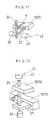
- Fig. 11 an example of the resistance welding (fifth embodiment) is shown.
- the external connection section 21 and the lead terminal 24 are positioned so as to partly overlap each other, and the overlap portion is clamped and pressed with electrodes 43, 43 of a resistance welding machine 42, then a current is applied to complete the welding.
- the external connection section 21 and the lead terminal 24 are connected.
- Such a resistance welding as illustrated in the fifth embodiment can be performed when the external connection section 21 and the lead terminal 24 are positioned so as to overlap as shown in Fig. 11.
- a resistance welding (sixth embodiment) shown in Fig. 12 can be employed to connect the external connection section 21 and the lead terminal 24.
- the lead terminal 24 is positioned with an end face thereof in contact with a face (upper face in Fig. 12) of the external connection section 21 and welded.
- a face upper face in Fig. 12
- the connection can be carried out stably even if the contact position to the lead terminal 24 varies some or less.
- the material of the terminal 23 is a phosphorous bronze, but the present invention is not limited to this material, but other materials such as a copper alloy may be used.
- a terminal consists integrally of a magnet wire binding section to connect to a magnet wire of a coil, an external connection section, and a support base section to press-fit into a terminal block.
- the support base section press-fits into the terminal block, the direction and position of the terminal are settled with the result that the stability is increased.
- a ground electrode of a plasma welding machine is connected to the external connection section, which is electrically continuous with the welding portion, whereby discharge current caused by plasma welding is allowed to flow.
- a magnet wire bound around the magnet wire binding section can be connected by means of fusing (plasma welding), with the result that the connection of the motor terminal can be carried out without using solder containing lead thereby saving material resources.
- lead is not used, the safety relating to the environmental pollution can be enhanced.
- the second aspect of the present invention since a projection and/or a recess for preventing the terminal from pulling out are provided on the support base section, the force of engaging with the terminal block is increased. As a result, the terminal can be held more stably to the terminal block.
- the length of the external connection section is set larger than that of the magnet wire binding section.
- the magnet wire binding section and the magnet wire of the coil are connected by means of fusing (plasma welding), with the result that the connection of the motor terminal is carried out without using solder containing lead.
- fusing plasma welding
- the magnet wire binding section and the magnet wire of the coil are connected by resistance welding, with the result that the connection of the motor terminal is carried out without using solder containing lead.
- material resources can be saved and the safety relating to the environmental pollution can be enhanced.
- the external connection section may be set longer than a second wing of the magnet wire binding section.
- the lead terminal and the external connection section can partly overlap and also the resistance welding thereof is made easier.
- the distance from the end of the binding of the magnet wire of the coil to the tip end of the second wing of the magnet wire binding section is set 0.5 mm or longer.
- the magnet wire of the coil can be prevented from subliming due to the energy of plasma (arc) , enabling the magnet wire of the coil to be connected to the magnet wire binding section by plasma welding.
- the distance is set 3 mm maximum, it does not happen that molten metal fails to reach the magnet wire, ensuring that the magnet wire of the coil is connected to the magnet wire binding section by plasma welding.
- a junction of the support base section, the external connection section and a first wing of the magnet wire binding section, as well as the support base section press-fits into the terminal block.
- the terminal is positioned duly and at the same time held securely, improving the workability.
- connection of the lead terminal and the external connection section is carried out by resistance welding. Therefore, material sources can be saved and welding can be done with a relatively general purpose equipment, resulting in reducing the cost of welding work and the cost of appliance.
- the lead terminal press-fits into a groove provided at the tip end of the external connection section.
- the external connection section can be guided to a groove at the widened portion of the lead terminal.
- the welding between the lead terminal and the external connection section can be carried out securely and stably.
Landscapes
- Engineering & Computer Science (AREA)
- Power Engineering (AREA)
- Manufacturing & Machinery (AREA)
- Insulation, Fastening Of Motor, Generator Windings (AREA)
- Motor Or Generator Frames (AREA)
Applications Claiming Priority (2)
| Application Number | Priority Date | Filing Date | Title |
|---|---|---|---|
| JP2000094002A JP2001286090A (ja) | 2000-03-30 | 2000-03-30 | モータ端子構造 |
| JP2000094002 | 2000-03-30 |
Publications (2)
| Publication Number | Publication Date |
|---|---|
| EP1139543A1 true EP1139543A1 (de) | 2001-10-04 |
| EP1139543B1 EP1139543B1 (de) | 2009-10-07 |
Family
ID=18609106
Family Applications (1)
| Application Number | Title | Priority Date | Filing Date |
|---|---|---|---|
| EP01106866A Expired - Lifetime EP1139543B1 (de) | 2000-03-30 | 2001-03-20 | Verbindungsanordnung für die Anschlüsse eines Elektromotors |
Country Status (4)
| Country | Link |
|---|---|
| US (1) | US6455962B2 (de) |
| EP (1) | EP1139543B1 (de) |
| JP (1) | JP2001286090A (de) |
| DE (1) | DE60140097D1 (de) |
Cited By (5)
| Publication number | Priority date | Publication date | Assignee | Title |
|---|---|---|---|---|
| EP1394922A1 (de) * | 2002-08-30 | 2004-03-03 | MINEBEA Co., Ltd. | Spule mit Abdeckung zum Schutz des magnetischen Drahtes |
| EP1583202A2 (de) * | 2004-03-30 | 2005-10-05 | MINEBEA Co., Ltd. | Schrittmotor mit doppelschichtiger Abdeckelplatte für Garnspullen |
| EP1608052A2 (de) | 2004-06-14 | 2005-12-21 | MINEBEA Co., Ltd. | Antrieb mit einer Erdungsklemme |
| EP2602871A1 (de) * | 2010-08-06 | 2013-06-12 | Traftor Technolo (Shenzhen) Co., Ltd | Drahtanschlussklemme für emaille-leiter |
| EP3614538A1 (de) * | 2018-08-21 | 2020-02-26 | Shinano Kenshi Co., Ltd. | Elektrische vorrichtung |
Families Citing this family (21)
| Publication number | Priority date | Publication date | Assignee | Title |
|---|---|---|---|---|
| JP3255164B2 (ja) * | 2000-01-28 | 2002-02-12 | 松下電器産業株式会社 | 小型偏平モータ |
| US6555937B2 (en) * | 2000-02-01 | 2003-04-29 | Denso Corporation | Vehicle alternator rectifier having L-shaped connection terminals |
| JP3617810B2 (ja) * | 2000-08-31 | 2005-02-09 | 三菱電機株式会社 | 回転電機 |
| JP2002125348A (ja) * | 2000-10-12 | 2002-04-26 | Suzuki Motor Corp | 配線接続装置 |
| JP3464444B2 (ja) * | 2000-10-30 | 2003-11-10 | 三菱電機株式会社 | 電磁機器 |
| AU2003266579A1 (en) * | 2002-09-24 | 2004-04-19 | Sawafuji Electric Co., Ltd. | Stator for outer rotor multipole generator and method of assembling the stator |
| JP2004153891A (ja) * | 2002-10-29 | 2004-05-27 | Mitsubishi Electric Corp | 回転電機 |
| JP4815299B2 (ja) * | 2006-07-31 | 2011-11-16 | 日本電産サンキョー株式会社 | モータ及びその製造方法 |
| US7495353B2 (en) * | 2006-08-01 | 2009-02-24 | Hamilton Sundstrand Corporation | Power interconnect block for an aircraft electrical component |
| TW200835118A (en) * | 2007-02-12 | 2008-08-16 | Delta Electronics Inc | Motor and stator structure thereof |
| JP5563272B2 (ja) | 2009-10-21 | 2014-07-30 | ミネベア株式会社 | ステッピングモータ |
| JP4832581B2 (ja) * | 2010-01-29 | 2011-12-07 | トヨタ自動車株式会社 | 回転電機用端子台 |
| US9819241B2 (en) | 2010-06-14 | 2017-11-14 | Black & Decker Inc. | Stator assembly for a brushless motor in a power tool |
| US8446058B2 (en) | 2010-09-20 | 2013-05-21 | General Electric Company | Electric motor terminal block assembly |
| JP5653746B2 (ja) * | 2010-12-24 | 2015-01-14 | ミネベア株式会社 | メータ用ステッピングモータ |
| JP6088762B2 (ja) * | 2012-07-30 | 2017-03-01 | ミネベアミツミ株式会社 | ステッピングモータ |
| JP6039976B2 (ja) * | 2012-09-12 | 2016-12-07 | ミネベア株式会社 | 多相コイル端子装置およびこれを備えたモータ |
| CN205081661U (zh) * | 2015-09-22 | 2016-03-09 | 大陆汽车电子(芜湖)有限公司 | 定子总成及包含该定子总成的步进驱动电机 |
| JP6334581B2 (ja) * | 2016-01-27 | 2018-05-30 | 株式会社東海理化電機製作所 | インシュレータ |
| CN110224536B (zh) * | 2018-03-02 | 2024-03-22 | 日本电产三协电子(东莞)有限公司 | 电机 |
| US11394285B2 (en) * | 2019-05-31 | 2022-07-19 | Minebea Mitsumi Inc. | Vibration actuator and electronic device |
Citations (6)
| Publication number | Priority date | Publication date | Assignee | Title |
|---|---|---|---|---|
| JPS62105409A (ja) * | 1985-11-01 | 1987-05-15 | Canon Inc | コイルボビン |
| US5004941A (en) * | 1988-12-09 | 1991-04-02 | Copal Co., Ltd. | Stepper motor with input connector array |
| JPH0564411A (ja) * | 1991-02-18 | 1993-03-12 | Seiko Epson Corp | Pm型ステツピングモータ |
| DE19534976A1 (de) * | 1994-10-13 | 1996-04-18 | Nippon Denso Co | Schrittmotor |
| EP0905860A2 (de) * | 1997-09-29 | 1999-03-31 | Sawafuji Electric Co., Ltd. | Spulenverbindungsvorrichtung für einen Ausseläufermultipolegenerator |
| US5912517A (en) * | 1996-02-21 | 1999-06-15 | Sankyo Seiki Mfg Co., Ltd. | Coil components and motor using the coil components having a terminal pin with a conducive connection member wound there around |
Family Cites Families (8)
| Publication number | Priority date | Publication date | Assignee | Title |
|---|---|---|---|---|
| JPS6294612U (de) * | 1985-12-03 | 1987-06-17 | ||
| JPS63129937U (de) * | 1987-02-18 | 1988-08-25 | ||
| KR910007671B1 (ko) * | 1988-08-17 | 1991-09-30 | 미쯔비시 덴끼 가부시끼가이샤 | 소형 전동기용 고정자 |
| JPH0354347U (de) * | 1989-09-28 | 1991-05-27 | ||
| US5264816A (en) * | 1991-01-09 | 1993-11-23 | Furnas Electric Company | Electrical winding termination structure |
| JP3102665B2 (ja) * | 1992-02-17 | 2000-10-23 | 三菱電機株式会社 | 電動機 |
| JPH0588169U (ja) * | 1992-04-22 | 1993-11-26 | マブチモーター株式会社 | 小型モータ |
| JP3421421B2 (ja) * | 1993-06-15 | 2003-06-30 | マブチモーター株式会社 | 小型モータ |
-
2000
- 2000-03-30 JP JP2000094002A patent/JP2001286090A/ja active Pending
-
2001
- 2001-03-13 US US09/803,909 patent/US6455962B2/en not_active Expired - Lifetime
- 2001-03-20 DE DE60140097T patent/DE60140097D1/de not_active Expired - Fee Related
- 2001-03-20 EP EP01106866A patent/EP1139543B1/de not_active Expired - Lifetime
Patent Citations (6)
| Publication number | Priority date | Publication date | Assignee | Title |
|---|---|---|---|---|
| JPS62105409A (ja) * | 1985-11-01 | 1987-05-15 | Canon Inc | コイルボビン |
| US5004941A (en) * | 1988-12-09 | 1991-04-02 | Copal Co., Ltd. | Stepper motor with input connector array |
| JPH0564411A (ja) * | 1991-02-18 | 1993-03-12 | Seiko Epson Corp | Pm型ステツピングモータ |
| DE19534976A1 (de) * | 1994-10-13 | 1996-04-18 | Nippon Denso Co | Schrittmotor |
| US5912517A (en) * | 1996-02-21 | 1999-06-15 | Sankyo Seiki Mfg Co., Ltd. | Coil components and motor using the coil components having a terminal pin with a conducive connection member wound there around |
| EP0905860A2 (de) * | 1997-09-29 | 1999-03-31 | Sawafuji Electric Co., Ltd. | Spulenverbindungsvorrichtung für einen Ausseläufermultipolegenerator |
Non-Patent Citations (2)
| Title |
|---|
| PATENT ABSTRACTS OF JAPAN vol. 11, no. 312 (E - 548) 12 October 1987 (1987-10-12) * |
| PATENT ABSTRACTS OF JAPAN vol. 17, no. 383 (E - 1400) 19 July 1993 (1993-07-19) * |
Cited By (10)
| Publication number | Priority date | Publication date | Assignee | Title |
|---|---|---|---|---|
| EP1394922A1 (de) * | 2002-08-30 | 2004-03-03 | MINEBEA Co., Ltd. | Spule mit Abdeckung zum Schutz des magnetischen Drahtes |
| US6897592B2 (en) | 2002-08-30 | 2005-05-24 | Minebea Co., Ltd. | Bobbin provided with cover for protecting magnet wire |
| EP1583202A2 (de) * | 2004-03-30 | 2005-10-05 | MINEBEA Co., Ltd. | Schrittmotor mit doppelschichtiger Abdeckelplatte für Garnspullen |
| EP1583202A3 (de) * | 2004-03-30 | 2007-02-28 | MINEBEA Co., Ltd. | Schrittmotor mit doppelschichtiger abdeckelplatte für Garnspullen |
| EP1608052A2 (de) | 2004-06-14 | 2005-12-21 | MINEBEA Co., Ltd. | Antrieb mit einer Erdungsklemme |
| EP1608052A3 (de) * | 2004-06-14 | 2007-05-09 | MINEBEA Co., Ltd. | Antrieb mit einer Erdungsklemme |
| EP2602871A1 (de) * | 2010-08-06 | 2013-06-12 | Traftor Technolo (Shenzhen) Co., Ltd | Drahtanschlussklemme für emaille-leiter |
| EP2602871A4 (de) * | 2010-08-06 | 2014-04-30 | Traftor Technology Shenzhen Co Ltd | Drahtanschlussklemme für emaille-leiter |
| US8951077B2 (en) | 2010-08-06 | 2015-02-10 | Traftor Technology (Shenzhen) Co., Ltd | Wire connecting terminal for enameled wires |
| EP3614538A1 (de) * | 2018-08-21 | 2020-02-26 | Shinano Kenshi Co., Ltd. | Elektrische vorrichtung |
Also Published As
| Publication number | Publication date |
|---|---|
| US20010026103A1 (en) | 2001-10-04 |
| DE60140097D1 (de) | 2009-11-19 |
| EP1139543B1 (de) | 2009-10-07 |
| JP2001286090A (ja) | 2001-10-12 |
| US6455962B2 (en) | 2002-09-24 |
Similar Documents
| Publication | Publication Date | Title |
|---|---|---|
| US6455962B2 (en) | Terminal structure of a motor | |
| KR910007562Y1 (ko) | 브러시레스 모터 | |
| US6369474B1 (en) | Alternating current generator for vehicle | |
| EP1404007A1 (de) | Vorrichtung und Verfahren zum Anschliessen eines Drehmelders | |
| EP1739809A1 (de) | Eine zentrale Energieverteilungsanordnung für einen bürstenlosen Motor, ein bürstenloser Motor damit und ein Verfahren zur Herstellung dafür | |
| US11605996B2 (en) | Electrical distribution member | |
| EP1126579B1 (de) | Stator eines Wechselstromgenerators | |
| US6853108B2 (en) | Rotor for small-sized motor and method of manufacturing same | |
| JPH07177694A (ja) | 小型モータ及びこの小型モータの端子装置の接続方法 | |
| CN110474461B (zh) | 马达的定子及其制造方法 | |
| KR20090007221A (ko) | 모터 | |
| CA2470712A1 (en) | Electric motor | |
| CN112787451A (zh) | 旋转电机以及旋转电机的制造方法 | |
| JP2002262520A (ja) | 小型モータの回転子及びその製造方法 | |
| US6611077B2 (en) | Motor having a commutator | |
| JP2000232746A (ja) | 圧縮機用電動機の固定子および電動圧縮機 | |
| CN110291698B (zh) | 旋转电机及其制造方法 | |
| US4975739A (en) | Electromagnetic relay | |
| US7414344B2 (en) | Commutator and an armature | |
| EP1021814B1 (de) | Elektromagnetisches Relais | |
| EP0201129B2 (de) | Methode zur Herstellung eines Teils einer elektrischen Maschine | |
| JPH09185933A (ja) | 電磁継電器の構造及び点溶接機 | |
| WO2023176339A1 (ja) | 回転電機のステータ、回転電機、回転電機のステータの製造方法、および、回転電機の製造方法 | |
| JP4572625B2 (ja) | モータ | |
| JPH06275446A (ja) | ボビン端子及びボビン端子付コイル装置 |
Legal Events
| Date | Code | Title | Description |
|---|---|---|---|
| PUAI | Public reference made under article 153(3) epc to a published international application that has entered the european phase |
Free format text: ORIGINAL CODE: 0009012 |
|
| AK | Designated contracting states |
Kind code of ref document: A1 Designated state(s): AT BE CH CY DE DK ES FI FR GB GR IE IT LI LU MC NL PT SE TR |
|
| AX | Request for extension of the european patent |
Free format text: AL;LT;LV;MK;RO;SI |
|
| 17P | Request for examination filed |
Effective date: 20020306 |
|
| AKX | Designation fees paid |
Free format text: DE FR |
|
| GRAP | Despatch of communication of intention to grant a patent |
Free format text: ORIGINAL CODE: EPIDOSNIGR1 |
|
| GRAS | Grant fee paid |
Free format text: ORIGINAL CODE: EPIDOSNIGR3 |
|
| GRAA | (expected) grant |
Free format text: ORIGINAL CODE: 0009210 |
|
| AK | Designated contracting states |
Kind code of ref document: B1 Designated state(s): DE FR |
|
| REF | Corresponds to: |
Ref document number: 60140097 Country of ref document: DE Date of ref document: 20091119 Kind code of ref document: P |
|
| PLBE | No opposition filed within time limit |
Free format text: ORIGINAL CODE: 0009261 |
|
| STAA | Information on the status of an ep patent application or granted ep patent |
Free format text: STATUS: NO OPPOSITION FILED WITHIN TIME LIMIT |
|
| 26N | No opposition filed |
Effective date: 20100708 |
|
| PG25 | Lapsed in a contracting state [announced via postgrant information from national office to epo] |
Ref country code: DE Free format text: LAPSE BECAUSE OF NON-PAYMENT OF DUE FEES Effective date: 20101001 |
|
| REG | Reference to a national code |
Ref country code: FR Ref legal event code: PLFP Year of fee payment: 16 |
|
| REG | Reference to a national code |
Ref country code: FR Ref legal event code: PLFP Year of fee payment: 17 |
|
| REG | Reference to a national code |
Ref country code: FR Ref legal event code: PLFP Year of fee payment: 18 |
|
| PGFP | Annual fee paid to national office [announced via postgrant information from national office to epo] |
Ref country code: FR Payment date: 20200214 Year of fee payment: 20 |