EP1137031A2 - Kontaktanordnung für elektromagnetische Schaltgeräte, insbesondere für Schütze - Google Patents
Kontaktanordnung für elektromagnetische Schaltgeräte, insbesondere für Schütze Download PDFInfo
- Publication number
- EP1137031A2 EP1137031A2 EP00121939A EP00121939A EP1137031A2 EP 1137031 A2 EP1137031 A2 EP 1137031A2 EP 00121939 A EP00121939 A EP 00121939A EP 00121939 A EP00121939 A EP 00121939A EP 1137031 A2 EP1137031 A2 EP 1137031A2
- Authority
- EP
- European Patent Office
- Prior art keywords
- contact
- housing
- abutment
- pressure spring
- contactors
- Prior art date
- Legal status (The legal status is an assumption and is not a legal conclusion. Google has not performed a legal analysis and makes no representation as to the accuracy of the status listed.)
- Withdrawn
Links
- 238000005452 bending Methods 0.000 claims description 2
- 230000005284 excitation Effects 0.000 description 3
- 238000004519 manufacturing process Methods 0.000 description 3
- 238000000034 method Methods 0.000 description 1
- 238000000926 separation method Methods 0.000 description 1
Images


Classifications
-
- H—ELECTRICITY
- H01—ELECTRIC ELEMENTS
- H01H—ELECTRIC SWITCHES; RELAYS; SELECTORS; EMERGENCY PROTECTIVE DEVICES
- H01H50/00—Details of electromagnetic relays
- H01H50/54—Contact arrangements
- H01H50/546—Contact arrangements for contactors having bridging contacts
Definitions
- the present invention relates to a contact arrangement for electromagnetic Switchgear, especially for contactors, with a housing, with in Housing arranged stationary and can be brought into and out of engagement with them, movable contact pieces, with one through the armature of the electromagnetic Drive longitudinally movable contact bridge carrier, in its window-like opening the movable contact piece with one on one housing-connected abutment supporting contact pressure spring can be moved longitudinally is arranged guided.
- From DE-A1-3440229 is a contact arrangement of the type mentioned known. This arrangement is used for the movable contact piece to achieve a constant lifting force characteristic.
- the contact pressure spring of the movable contact piece not as previously known on Contact carrier, but supported on a housing-connected abutment.
- the electromagnetic switching device To be able to mount the abutment is for the electromagnetic switching device a two-part housing is provided. By closing the housing halves the abutment is caught, the correct position of the abutment only accessible through special, expensive guide surfaces in the housing is. The abutment is uncontrolled when the housing halves are closed between these.
- the object of the present invention is to provide a contact arrangement for electromagnetic Develop switchgear, especially for contactors, at which the contact pressure spring of the movable contact piece is supported on the housing is economical in terms of production and also automated assembly is advantageous.
- the task is solved in that the housing is transverse to the direction the contact movement is formed in one piece and that the one for the contact pressure spring provided abutment provided centering through the window-like
- the opening of the contact bridge carrier is inserted under the contact pressure spring and is held in the housing by positive connections.
- the one-piece design of the housing is simple to manufacture and spares an assembly of housing halves.
- the abutment is proportionate to the simple and also automatable assembly under the contact pressure spring inserted and in the housing by positive connections held.
- the abutment can rest on the housing with both ends.
- the two-sided Support of the abutment is sufficient, especially for switchgear with a large housing advantageous.
- the abutment can also be designed like a console and only with its one End area in the housing be secured against bending.
- the console-like training the abutment can be especially in the case of relatively smaller housings Switchgear bring advantages.
- the electromagnetic switching device shown in section in Figure 1, or Schütz has one composed of an upper part 1 and a lower part 2 Housing on.
- the upper part 1 of the housing contains the fastened therein stationary contact pieces 3, 4.
- the arranged on a contact bridge 5 movable contact pieces 6, 7 are with the fixed contact pieces 3, 4 in and disengageable.
- the contact bridge 5 is in a window-like Opening 8 of the contact bridge support 9 and can be in the switching direction be moved.
- the contact bridge support 9 is connected to the armature 10 of the Electromagnets of the electromagnetic drive coupled, as in the EP-A2-0739021.
- the contact bridge 5 is at a by excitation of the electromagnetic Drive causes the switching device to switch off via a towing connection brought with the contact bridge support 9 in the off position.
- the contact bridge 5 In the event of an interruption in the excitation of the electromagnetic drive caused switch-on movement of the switching device, the contact bridge 5 from by a spring moving contact bridge carrier 9 in the switch-on direction Cut. The contact bridge 5 is then in 11 by the contact pressure spring brought the switch on.
- the contact pressure spring 11 is on a housing-connected abutment 12 a centering point 13 formed thereon.
- This abutment 12 is in FIG. 2 from above and in FIG. 3 from below, on a different scale shown.
- the abutment 12 is bar-shaped and lies with its two End areas on the upper part 1 of the housing. Because the top part 1 of the housing transversely to the direction of the contact movement, the abutment 12 at the assembly of the contactor from the side through the window-like opening 8 of the Contact bridge support 9 pushed under the contact pressure spring 11. In the Operating position is the abutment 12 by positive connections in the held in the correct position.
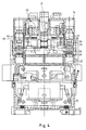
- FIG. 4 shows another electromagnetic switching device in section. Also at this switching device is the housing of an upper part 14 and a lower part 15 composed. Both the upper part and the lower part 15 are formed in one piece transversely to the direction of the contact movement.
- the fixed contact pieces 16, 17 are attached to the housing.
- the one Contact bridge 18 arranged movable contact pieces 19, 20 are with the stationary contact pieces 16, 17 can be disengaged by the contact bridge carrier 21 moved by the armature 22 of the electromagnetic drive becomes.
- the contact bridge 18 lies in a window-like opening 23 of the contact bridge support 21 and can be in the direction of movement of the armature 22 be moved.
- the contact bridge 18 is over when the switching device is switched off a towing connection with the contact bridge carrier 21 against the force of Contact pressure spring 24 brought into the off position.
- the separation of the movable contact pieces 19, 20 of the fixed contact pieces 16, 17 takes place.
- the contact pressure spring 24 is on a housing-connected abutment 25 a centering point 26 formed thereon is supported.
- This abutment 25 is shown in perspective in a different scale in FIG.
- the abutment 25 is formed like a console and only with its one end region in the upper part 14 attached to the housing.
- the upper part 14 of the housing is transverse to the direction of the Contact movement in one piece.
- the abutment 25 must therefore when installing the Switching device inserted from the side under the contact pressure spring 24 become.
- For holding the abutment 25 are in the upper part 14 of the housing positive connections molded.
Landscapes
- Physics & Mathematics (AREA)
- Electromagnetism (AREA)
- Contacts (AREA)
Abstract
Description
- Fig.1
- ein elektromagnetisches Schaltgerät im Schnitt mit einem beidseitig im Gehäuse abgestützten Widerlager für die Kontaktdruckfeder und
- Fig.2
- das Widerlager allein von oben her gesehen,
- Fig.3
- das Widerlager allein von unten her gesehen,
- Fig.4
- ein weiteres elektromagnetisches Schaltgerät im Schnitt mit einem mit seinem einen Ende im Gehäuse befestigten konsolenartigen Widerlager für die Kontaktdruckfeder,
- Fig.5
- dieses Widerlager in perspektivischer Darstellung.
Claims (3)
- Kontaktanordnung für elektromagnetische Schaltgeräte, insbesondere für Schütze, mit einem Gehäuse (1, 2, 14, 15), mit im Gehäuse (1, 2, 14, 15) angeordneten ortsfesten und mit diesen in und ausser Eingriff bringbaren, beweglichen Kontaktstücken (3, 4, 16, 17, 6, 7, 19, 20), mit einem durch den Anker (10, 22) des elektromagnetischen Antriebes längsverschiebbaren Kontaktbrückenträger (9, 21), in dessen fensterartiger Oeffnung (8, 23) das bewegliche Kontaktstück (6, 7, 19, 20) mit einer sich an einem gehäuseverbundenen Widerlager (12, 25) abstützenden Kontaktdruckfeder (11, 24) längsverschiebbar geführt angeordnet ist, dadurch gekennzeichnet, dass das Gehäuse (1, 2, 14, 15) quer zur Richtung der Kontaktbewegung einteilig ausgebildet ist und dass das eine für die Kontaktdruckfeder (11, 24) vorgesehene Zentrierstelle (13, 26) aufweisende Widerlager (12, 25) durch die fensterartige Oeffnung (8, 23) des Kontaktbrückenträgers (9, 21) unter die Kontaktdruckfeder (11, 24) eingeschoben und im Gehäuse (1, 2, 14, 15) durch formschlüssige Verbindungen gehalten ist.
- Kontaktanordnung nach Anspruch 1, dadurch gekennzeichnet, dass das Widerlager (12) mit beiden Enden am Gehäuse (1, 2) aufliegt.
- Kontaktanordnung nach Anspruch 1, dadurch gekennzeichnet, dass das Widerlager (25) konsolenartig ausgebildet ist und nur mit seinem einen Endbereich im Gehäuse (14, 15) biegefest befestigt ist.
Applications Claiming Priority (2)
| Application Number | Priority Date | Filing Date | Title |
|---|---|---|---|
| CH5672000 | 2000-03-24 | ||
| CH5672000 | 2000-03-24 |
Publications (2)
| Publication Number | Publication Date |
|---|---|
| EP1137031A2 true EP1137031A2 (de) | 2001-09-26 |
| EP1137031A3 EP1137031A3 (de) | 2004-01-02 |
Family
ID=4520659
Family Applications (1)
| Application Number | Title | Priority Date | Filing Date |
|---|---|---|---|
| EP00121939A Withdrawn EP1137031A3 (de) | 2000-03-24 | 2000-10-09 | Kontaktanordnung für elektromagnetische Schaltgeräte, insbesondere für Schütze |
Country Status (2)
| Country | Link |
|---|---|
| EP (1) | EP1137031A3 (de) |
| JP (1) | JP2001307608A (de) |
Families Citing this family (1)
| Publication number | Priority date | Publication date | Assignee | Title |
|---|---|---|---|---|
| JP5134657B2 (ja) * | 2010-07-27 | 2013-01-30 | 富士電機機器制御株式会社 | 接点機構及びこれを使用した電磁接触器 |
Family Cites Families (3)
| Publication number | Priority date | Publication date | Assignee | Title |
|---|---|---|---|---|
| JPS6070625A (ja) * | 1983-09-27 | 1985-04-22 | 三菱電機株式会社 | 電磁開閉器の接点装置 |
| DD220846B5 (de) * | 1984-01-31 | 1994-05-05 | Oppach Schaltelektronik | Schaltsystemanordnung fuer elektromagnetische Schaltgeraete |
| JP3338216B2 (ja) * | 1994-12-13 | 2002-10-28 | 三菱電機株式会社 | 切換スイッチ |
-
2000
- 2000-10-09 EP EP00121939A patent/EP1137031A3/de not_active Withdrawn
-
2001
- 2001-03-22 JP JP2001083411A patent/JP2001307608A/ja active Pending
Also Published As
| Publication number | Publication date |
|---|---|
| JP2001307608A (ja) | 2001-11-02 |
| EP1137031A3 (de) | 2004-01-02 |
Similar Documents
| Publication | Publication Date | Title |
|---|---|---|
| EP0719395B1 (de) | Modulares ventil für strömende medien | |
| EP1968083B1 (de) | Relais | |
| EP2131377A1 (de) | Relais mit Doppel-Ankerwippe | |
| EP2009665B1 (de) | 2-poliges Relais | |
| EP1843377B1 (de) | Magnetantrieb für ein Relais | |
| EP0134293B1 (de) | Schaltvorrichtung, insbesondere für Endschalter oder Grenztaster | |
| DE69300185T2 (de) | Lichtbogenkammern begrenzendes Teil. | |
| EP0739021A2 (de) | Elektromagnetisches Schaltgerät, insbesondere Schütz | |
| DE102012201967A1 (de) | Schaltkontaktbaugruppe sowie Bausatz und Montageverfahren hierfür | |
| EP1137031A2 (de) | Kontaktanordnung für elektromagnetische Schaltgeräte, insbesondere für Schütze | |
| DE2118633B2 (de) | Klappankerschütz mit Wechselkontaktsätzen | |
| WO2002027739A1 (de) | Schaltkontaktanordnung eines niederspannungs-leistungsschalters mit kontaktkraftfedern | |
| DE2142464C3 (de) | Anordnung zur gelenkigen Verbindung des Ankers eines elektromagnetischen Schaltgerätes mit dem Kontaktbrückenträger | |
| EP0015228B1 (de) | Fernsteuerbare Antriebsvorrichtung für Schutzschalter mit einem Elektromagneten | |
| EP3055872B1 (de) | Kontaktschiebereinheit für eine schalteinheit | |
| DE1614837B2 (de) | Elektromagnetisches schuetz | |
| DE2416152A1 (de) | Leistungsschalter | |
| AT208449B (de) | Schaltvorrichtung für elektrische Schalter | |
| DE19956885B4 (de) | Befehlsgerät | |
| DE19904623C2 (de) | Schalter, vorzugsweise Relais | |
| DE1140261B (de) | Brueckenkontaktanordnung fuer elektrische Schaltgeraete | |
| DE2702851B2 (de) | Bimetallgesteuerter Schalter | |
| DE449401C (de) | Schalter mit einer Anzahl hintereinander geschalteter Kontaktglieder im Nebenkontaktweg | |
| DE1615838C (de) | Relaiskontaktanordnung | |
| DE19948695B4 (de) | Niederspannungs-Leistungsschalter mit einem bewegbaren Kontaktträger mit Endlagen-Haltefeder |
Legal Events
| Date | Code | Title | Description |
|---|---|---|---|
| PUAI | Public reference made under article 153(3) epc to a published international application that has entered the european phase |
Free format text: ORIGINAL CODE: 0009012 |
|
| AK | Designated contracting states |
Kind code of ref document: A2 Designated state(s): AT BE CH CY DE DK ES FI FR GB GR IE IT LI LU MC NL PT SE |
|
| AX | Request for extension of the european patent |
Free format text: AL;LT;LV;MK;RO;SI |
|
| PUAL | Search report despatched |
Free format text: ORIGINAL CODE: 0009013 |
|
| AK | Designated contracting states |
Kind code of ref document: A3 Designated state(s): AT BE CH CY DE DK ES FI FR GB GR IE IT LI LU MC NL PT SE |
|
| AX | Request for extension of the european patent |
Extension state: AL LT LV MK RO SI |
|
| STAA | Information on the status of an ep patent application or granted ep patent |
Free format text: STATUS: THE APPLICATION HAS BEEN WITHDRAWN |
|
| 18W | Application withdrawn |
Effective date: 20040119 |