EP1136860A2 - Connecteur multifibre, outil d'installation et méthodes associées pour validation de la continuité d'une fibre optique - Google Patents
Connecteur multifibre, outil d'installation et méthodes associées pour validation de la continuité d'une fibre optique Download PDFInfo
- Publication number
- EP1136860A2 EP1136860A2 EP20010107178 EP01107178A EP1136860A2 EP 1136860 A2 EP1136860 A2 EP 1136860A2 EP 20010107178 EP20010107178 EP 20010107178 EP 01107178 A EP01107178 A EP 01107178A EP 1136860 A2 EP1136860 A2 EP 1136860A2
- Authority
- EP
- European Patent Office
- Prior art keywords
- fiber
- optical
- optical field
- fibers
- optical fiber
- Prior art date
- Legal status (The legal status is an assumption and is not a legal conclusion. Google has not performed a legal analysis and makes no representation as to the accuracy of the status listed.)
- Withdrawn
Links
- 239000013307 optical fiber Substances 0.000 title claims abstract description 192
- 238000000034 method Methods 0.000 title claims abstract description 42
- 238000009434 installation Methods 0.000 title abstract description 85
- 239000000835 fiber Substances 0.000 claims abstract description 375
- 230000003287 optical effect Effects 0.000 claims abstract description 223
- 230000007246 mechanism Effects 0.000 claims abstract description 46
- 238000002788 crimping Methods 0.000 claims description 7
- 238000012544 monitoring process Methods 0.000 claims description 5
- 238000011156 evaluation Methods 0.000 claims description 4
- 238000004140 cleaning Methods 0.000 claims 2
- 238000012360 testing method Methods 0.000 abstract description 32
- 238000010200 validation analysis Methods 0.000 abstract description 3
- LGDAGYXJBDILKZ-UHFFFAOYSA-N [2-methyl-1,1-dioxo-3-(pyridin-2-ylcarbamoyl)-1$l^{6},2-benzothiazin-4-yl] 2,2-dimethylpropanoate Chemical compound CC(C)(C)C(=O)OC=1C2=CC=CC=C2S(=O)(=O)N(C)C=1C(=O)NC1=CC=CC=N1 LGDAGYXJBDILKZ-UHFFFAOYSA-N 0.000 description 23
- 230000008569 process Effects 0.000 description 8
- 238000003780 insertion Methods 0.000 description 7
- 230000037431 insertion Effects 0.000 description 7
- 239000000428 dust Substances 0.000 description 4
- 241000723418 Carya Species 0.000 description 2
- 239000004593 Epoxy Substances 0.000 description 2
- 239000000853 adhesive Substances 0.000 description 2
- 230000001070 adhesive effect Effects 0.000 description 2
- 230000003247 decreasing effect Effects 0.000 description 2
- 238000012986 modification Methods 0.000 description 2
- 230000004048 modification Effects 0.000 description 2
- LFQSCWFLJHTTHZ-UHFFFAOYSA-N Ethanol Chemical compound CCO LFQSCWFLJHTTHZ-UHFFFAOYSA-N 0.000 description 1
- 230000000712 assembly Effects 0.000 description 1
- 238000000429 assembly Methods 0.000 description 1
- 230000008901 benefit Effects 0.000 description 1
- 230000008859 change Effects 0.000 description 1
- 238000007796 conventional method Methods 0.000 description 1
- 238000013461 design Methods 0.000 description 1
- 230000000694 effects Effects 0.000 description 1
- 238000004519 manufacturing process Methods 0.000 description 1
- 238000012956 testing procedure Methods 0.000 description 1
- 238000003466 welding Methods 0.000 description 1
Images


Classifications
-
- G—PHYSICS
- G02—OPTICS
- G02B—OPTICAL ELEMENTS, SYSTEMS OR APPARATUS
- G02B6/00—Light guides; Structural details of arrangements comprising light guides and other optical elements, e.g. couplings
- G02B6/24—Coupling light guides
- G02B6/36—Mechanical coupling means
- G02B6/38—Mechanical coupling means having fibre to fibre mating means
- G02B6/3807—Dismountable connectors, i.e. comprising plugs
-
- G—PHYSICS
- G02—OPTICS
- G02B—OPTICAL ELEMENTS, SYSTEMS OR APPARATUS
- G02B6/00—Light guides; Structural details of arrangements comprising light guides and other optical elements, e.g. couplings
- G02B6/24—Coupling light guides
- G02B6/26—Optical coupling means
-
- G—PHYSICS
- G02—OPTICS
- G02B—OPTICAL ELEMENTS, SYSTEMS OR APPARATUS
- G02B6/00—Light guides; Structural details of arrangements comprising light guides and other optical elements, e.g. couplings
- G02B6/24—Coupling light guides
- G02B6/36—Mechanical coupling means
- G02B6/38—Mechanical coupling means having fibre to fibre mating means
- G02B6/3807—Dismountable connectors, i.e. comprising plugs
- G02B6/3833—Details of mounting fibres in ferrules; Assembly methods; Manufacture
- G02B6/3846—Details of mounting fibres in ferrules; Assembly methods; Manufacture with fibre stubs
-
- G—PHYSICS
- G02—OPTICS
- G02B—OPTICAL ELEMENTS, SYSTEMS OR APPARATUS
- G02B6/00—Light guides; Structural details of arrangements comprising light guides and other optical elements, e.g. couplings
- G02B6/24—Coupling light guides
- G02B6/36—Mechanical coupling means
- G02B6/38—Mechanical coupling means having fibre to fibre mating means
- G02B6/3807—Dismountable connectors, i.e. comprising plugs
- G02B6/3869—Mounting ferrules to connector body, i.e. plugs
-
- G—PHYSICS
- G02—OPTICS
- G02B—OPTICAL ELEMENTS, SYSTEMS OR APPARATUS
- G02B6/00—Light guides; Structural details of arrangements comprising light guides and other optical elements, e.g. couplings
- G02B6/24—Coupling light guides
- G02B6/36—Mechanical coupling means
- G02B6/38—Mechanical coupling means having fibre to fibre mating means
- G02B6/3807—Dismountable connectors, i.e. comprising plugs
- G02B6/3898—Tools, e.g. handheld; Tuning wrenches; Jigs used with connectors, e.g. for extracting, removing or inserting in a panel, for engaging or coupling connectors, for assembling or disassembling components within the connector, for applying clips to hold two connectors together or for crimping
-
- G—PHYSICS
- G02—OPTICS
- G02B—OPTICAL ELEMENTS, SYSTEMS OR APPARATUS
- G02B6/00—Light guides; Structural details of arrangements comprising light guides and other optical elements, e.g. couplings
- G02B6/46—Processes or apparatus adapted for installing or repairing optical fibres or optical cables
- G02B6/47—Installation in buildings
- G02B6/475—Mechanical aspects of installing cables in ducts or the like for buildings
-
- G—PHYSICS
- G02—OPTICS
- G02B—OPTICAL ELEMENTS, SYSTEMS OR APPARATUS
- G02B6/00—Light guides; Structural details of arrangements comprising light guides and other optical elements, e.g. couplings
- G02B6/24—Coupling light guides
- G02B6/36—Mechanical coupling means
- G02B6/38—Mechanical coupling means having fibre to fibre mating means
- G02B6/3801—Permanent connections, i.e. wherein fibres are kept aligned by mechanical means
- G02B6/3806—Semi-permanent connections, i.e. wherein the mechanical means keeping the fibres aligned allow for removal of the fibres
-
- G—PHYSICS
- G02—OPTICS
- G02B—OPTICAL ELEMENTS, SYSTEMS OR APPARATUS
- G02B6/00—Light guides; Structural details of arrangements comprising light guides and other optical elements, e.g. couplings
- G02B6/24—Coupling light guides
- G02B6/36—Mechanical coupling means
- G02B6/38—Mechanical coupling means having fibre to fibre mating means
- G02B6/3807—Dismountable connectors, i.e. comprising plugs
- G02B6/3833—Details of mounting fibres in ferrules; Assembly methods; Manufacture
- G02B6/3834—Means for centering or aligning the light guide within the ferrule
- G02B6/3843—Means for centering or aligning the light guide within the ferrule with auxiliary facilities for movably aligning or adjusting the fibre within its ferrule, e.g. measuring position or eccentricity
-
- G—PHYSICS
- G02—OPTICS
- G02B—OPTICAL ELEMENTS, SYSTEMS OR APPARATUS
- G02B6/00—Light guides; Structural details of arrangements comprising light guides and other optical elements, e.g. couplings
- G02B6/24—Coupling light guides
- G02B6/36—Mechanical coupling means
- G02B6/38—Mechanical coupling means having fibre to fibre mating means
- G02B6/3807—Dismountable connectors, i.e. comprising plugs
- G02B6/3873—Connectors using guide surfaces for aligning ferrule ends, e.g. tubes, sleeves, V-grooves, rods, pins, balls
- G02B6/3885—Multicore or multichannel optical connectors, i.e. one single ferrule containing more than one fibre, e.g. ribbon type
-
- G—PHYSICS
- G02—OPTICS
- G02B—OPTICAL ELEMENTS, SYSTEMS OR APPARATUS
- G02B6/00—Light guides; Structural details of arrangements comprising light guides and other optical elements, e.g. couplings
- G02B6/44—Mechanical structures for providing tensile strength and external protection for fibres, e.g. optical transmission cables
- G02B6/4439—Auxiliary devices
- G02B6/4457—Bobbins; Reels
- G02B6/4458—Coiled, e.g. extensible helix
Definitions
- the present invention relates generally to the connectorization of optical fibers and, more particularly, to multifiber connectors, installation tools and associated methods for validating optical fiber continuity during the connectorization process.
- fiber optic connectors can generally be most efficiently and reliably mounted upon the end portions of optical fibers in a factory setting during the production of fiber optic cable, many fiber optic connectors must be mounted upon the end portions of optical fibers in the field. As such, a number of fiber optic connectors have been specifically developed to facilitate field installation.
- One advantageous type of fiber optic connector that is specifically designed to facilitate field installation is the UNICAM® family of fiber optic connectors provided by Siecor Corporation of Hickory, North Carolina.
- the UNICAM family of fiber optic connectors includes a number of common features including a common splicing technique
- the UNICAM family of fiber optic connectors has several different styles of connectors including UNICAM connectors adapted to be mounted upon a single optic fiber and UNICAM connectors adapted to be mounted upon two or more optical fibers, such as the MT-RJ UNICAM connector.
- UNICAM connectors adapted to be mounted upon a single optic fiber
- UNICAM connectors adapted to be mounted upon two or more optical fibers such as the MT-RJ UNICAM connector.
- Figure 1 depicts an MT-RJ UNICAM® connector 10.
- the connector generally includes a ferrule 12 defining one or more bores for receiving respective optical fiber stubs.
- the optical fiber stubs are preferably sized such that one end of the optic fiber stubs extends rearwardly beyond the ferrule.
- the MT-RJ UNICAM® connector also includes splice components, at least one of which defines a groove for receiving an end portion of each optical field fiber upon which the fiber optic connector is to be mounted.
- the splice components are positioned proximate the rear end of the ferrule, such that the end portions of the optical fibers stubs that extend rearwardly beyond the ferrule are disposed within the respective grooves defined by the splice components. Thereafter, end portions of the optical field fibers can also be inserted into the respective grooves defined by the splice components. By inserting the optical field fibers into the grooves defined by the splice components until respective end portions of the optical fiber stubs and the optical field fibers make contact, optical connections can be established between respective pairs of the optical fiber stubs and the optical field fibers.
- the contact between the end portions of the optical fiber stubs and the optical field fibers establishes optical continuity between respective pairs of the optical fiber stubs and the optical field fibers.
- the splice components can then be actuated, such as by means of a cam member 20 , in order to force the splice components together and to secure the end portions of the optical fiber stubs and the optical field fiber in position within the respective grooves defined by the splice components.
- U.S. Patent No. 5,040,867 to Michael de Jong et al. and U.S. Patent No. 5,261,020 to Michael de Jong et al. describe installation tools for facilitating the connectorization of optical fibers in the field.
- a UNICAM® installation tool kit is provided by Siecor Corporation of Hickory, North Carolina, to facilitate the mounting of the UNICAM® family of connectors upon the end portions of optical field fibers in the field.
- An installation tool holds a number of components of the fiber optic connector including the ferrule and the splice components while the optical field fibers are inserted into the fiber optic connector and aligned with the respective optical fiber stubs.
- one conventional installation tool includes a base and a tool housing mounted upon the base.
- the installation tool also includes an adapter disposed within the tool housing.
- the adapter has a first end for engaging the fiber optic connector that is to be mounted upon the optical field fibers and an opposed second end that is a dust cap.
- the installation tool also includes a bias member mounted within the tool housing that engages a shoulder defined between the first and second ends of the adapter in order to secure the adapter in position within the tool housing.
- the bias member includes a slide member slidably connected to the tool housing and a biasing element, such as a spring, for urging the slide member into engagement with the shoulder defined by the adapter.
- the slide member generally includes an engagement portion having a U-shape through which the second end of the adapter extends.
- a conventional slide member includes a base portion disposed between the tool housing and the base and connected to the engagement portion by means of a connecting element that extends through a lengthwise extending slot defined by the tool housing.
- the fiber optic connector In order to mount the fiber optic connector upon the end portions of the optical field fibers, the fiber optic connector is mounted within the installation tool.
- the forward end of the fiber optic connector is engaged by the first end of the adapter which, in turn, is secured within the tool housing once the slide member is biased into engagement with the shoulder defined by the adapter.
- the end portions of the optical field fibers are then inserted into the rear end of the fiber optic connector and the splice components are subsequently actuated, such as by being cammed together, in order to secure the optical field fibers relative to respective optical fiber stubs.
- the crimp tube 24 of the fiber optic connector is then crimped about the optical field fibers and, in some applications, a crimp band 26 is crimped to the strength members surrounding the optical field fibers in order to provide strain relief and otherwise protect the splice connections of the optical field fibers and the optical fiber stubs.
- the resulting fiber optic cable assembly is preferably tested end-to-end.
- this testing is designed to insure that optical continuity has been established between the optical fiber stubs and respective optical field fibers.
- fiber optic cables can be tested in different manners, one test involves the introduction of light having a predetermined intensity into each optical fiber stub. By measuring the light following its propagation through the fiber optic cable assembly and, more particularly, by measuring the insertion loss and back reflectance onto each optical fiber stub with a power meter, the continuity of each optical field fiber and the respective optical fiber stub can be determined.
- the technician must either scrap the entire fiber optic cable assembly or, more commonly, replace one or both fiber optic connectors in an attempt to establish the desired continuity.
- a technician In order to replace the fiber optic connectors, a technician generally removes, i.e., cuts off, one of the fiber optic connectors and repeats the connectorization process described above by mounting a new fiber optic connector within the installation tool and inserting the optical field fibers into the new fiber optic connector. Once the new fiber optic connector has been mounted upon the end portions of the optical field fibers, the new fiber optic connector is removed from the installation tool and the fiber optic cable assembly is again tested. If the optical fibers are still not sufficiently continuous, the fiber optic connector mounted upon the other end of the fiber optic cable assembly is typically removed and replaced as described above, prior to further testing of the resulting fiber optic cable assembly.
- the reconnectorization of one or both ends of a fiber optic cable assembly is particularly troublesome for fiber optic cable assemblies that include a plurality of optical field fibers.
- the testing indicates a discontinuity involving any one of the optical field fibers
- the fiber optic connectors mounted upon one or both ends of the fiber optic cable assembly must generally be replaced, even if the other optical field fibers and the optical fiber stubs have the desired continuity.
- Siecor Corporation In order to facilitate continuity testing while the fiber optic connector remains mounted within the installation tool, Siecor Corporation previously developed a modified installation tool for a single fiber CamLiteTM ST connector that permitted continuity testing.
- the installation tool included an adapter having opposed first and second ends, the first end of which was adapted to engage a single fiber CamLite ST connector.
- a laser such as an HeNe gas laser
- This other ST connector was, in turn, inserted into the second end of the adapter such that the red light was delivered to the optical fiber stub of the single fiber CamLite ST connector.
- the technician could determine when contact was established between the optical fiber stub and the optical field fiber based upon the dissipation of the glow, i.e., continuity is presumed to have been established once the glow dissipates. Thereafter, the cam member of the single fiber CamLite ST connector could be actuated to fix the relative positions of the optical field fiber and the optical fiber stub prior to making a final check of continuity.
- the modified installation tool developed by Siecor Corporation was only capable of mounting a fiber optic connector upon a single optical fiber and, more particularly, mounting a CamLite ST connector upon a single optical fiber and did not permit multifiber connectors to be mounted upon the end portions of a plurality of optical field fibers.
- improved techniques for mounting multifiber connectors upon optical field fibers in the field and for testing the resulting fiber optic cable assembly are desired in order to reduce the overall time required for the mounting and testing procedures and to correspondingly reduce the cost of the resulting fiber optic cable assembly.
- the fiber optic connector can be mounted upon an optical field fiber by actuating a cam mechanism to secure the optical field fiber in position relative to an optical fiber stub. If subsequent evaluation indicates that the continuity of the optical field fiber and the optical fiber stub is unacceptable, the cam mechanism can be deactuated, the optical field fiber can be repositioned and the cam mechanism can be reactuated without having to remove and replace the fiber optic connector.
- a method is also provided that introduces light into at least one of each pair of optical field fibers and optical fiber stubs and that only secures the position of each optical field fiber relative to the respective optical fiber stub once the glow associated with each pair of optical field fibers and optical fiber stubs dissipates, which dissipation indicates the establishment of continuity.
- An improved multifiber connector and installation tool are also provided to facilitate the establishment and validation of the continuity of optical field fibers and optical fiber stubs in order to reduce the time and cost required to connectorize optical field fibers in the field.
- the fiber optic connector includes a ferrule defining at least one bore extending between opposed front and rear faces, an optical fiber stub extending through the bore and beyond the rear face of the ferrule, and a cam mechanism.
- an optical field fiber is advanced into the fiber optic connector while light is introduced into at least one of the optical field fiber and the optical fiber stub. So long as the optical field fiber and the optical fiber stub are discontinuous, a glow will emanate from an end portion of the optical field fiber or the optical fiber stub into which light is introduced.
- the glow is monitored while the optical field fiber is advanced into the fiber optic connector and further advancement of the optical field fiber is halted once the glow dissipates.
- the cam mechanism is then actuated to secure the optical field fiber in position relative to the optional fiber stub. Once the cam mechanism has been actuated, the continuity of the optical field fiber and the optical fiber stub is evaluated, preferably while the fiber optic connector remains within the installation tool. If the continuity of the optical field fiber and the optical fiber stub is unacceptable, the cam mechanism is deactuated. The optical field fiber is then repositioned relative to the optical fiber stub. In this regard, the optical field fiber is typically cleaved and cleaned prior to the repositioning to improve the resulting connection.
- the cam mechanism is reactuated.
- the evaluation of the continuity of the optical field fiber and the optical fiber stub as well as any necessary deactuation of the cam mechanism, repositioning of the optical field fiber and reactuation of the cam mechanism can be repeated as necessary to achieve continuity.
- the fiber optic connector can be crimped onto the optical field fibers and, more typically, to the strength members surrounding the optical field fibers.
- the method of this embodiment prevents otherwise acceptable fiber optic connectors from being replaced in an attempt to establish continuity between optical field fibers and optical fiber stubs.
- the total time required to mount the fiber optic connectors upon the optical field fibers and to validate the resulting continuity of the optical fibers is decreased according to the method of this embodiment of the present invention.
- the cost of the resulting fiber optic cable assembly is also decreased since fewer fiber optic connectors are removed and scrapped.
- a multifiber connector is also provided according to another embodiment of the present invention.
- the multifiber connector of this embodiment includes a multifiber ferrule extending lengthwise between opposed front and rear faces for receiving a plurality of optical fiber stubs.
- the multifiber connector also includes splice components positioned proximate the rear face of the multifiber ferrule for aligning a plurality of optical field fibers with respective ones of the plurality of optical fibers stubs.
- the multifiber connector also includes a cam mechanism for urging the splice components together to operably interconnect respective pairs of the optical field fibers and the optical fibers stubs.
- At least one of the cam mechanism and the splice components is translucent such that the glow emanating from therewithin that is indicative of a discontinuity between at least one pair of optical field fibers and optical fibers stubs is externally visible.
- the cam mechanism of the multifiber connector includes a sleeve in which the splice components are disposed.
- the sleeve of this embodiment also defines a window through which the splice components are exposed.
- the cam mechanism of this embodiment includes a cam member disposed upon the sleeve for engaging the splice components via the window defined by the sleeve. As such, movement of the cam member relative to the sleeve urges the splice components together.
- the cam member is typically translucent.
- the multifiber connector of this embodiment of the present invention permits the connectorization process to be monitored to ensure that continuity is established between each optical field fiber and the respective optical fiber stubs prior to actuating the cam mechanism to secure the optical field fibers in position relative to the respective optical fiber stubs.
- An installation tool is also provided according to another embodiment of the present invention for mounting the fiber optic connector upon one or more optical field fibers.
- the installation tool of this embodiment is capable of being converted between a first configuration that facilitates validation of the continuity of the optical fibers and a second configuration in which the continuity of the optical fibers is untested.
- the installation tool includes a tool housing extending lengthwise between first and second opposed ends.
- the installation tool also include first and second adapters capable of being alternately mounted within the tool housing to configure the installation tool in the first and second configurations, respectively.
- the first adapter has a first end adapted to engage the fiber optic connector that is being mounted upon the optical field fiber and an opposed second end adapted to engage a fiber optic connector that is mounted upon another optical fiber that delivers light for continuity testing.
- the second adapter also has a first end adapted to engage the fiber optic connector that is mounted upon the optical field fiber, the second end of the second adapter serves as a dust cap.
- Each adapter further defines a shoulder between the opposed first and second ends.
- the installation tool of this embodiment of the present invention also includes first and second bias members capable of being alternately mounted within the tool housing to configure the installation tool in the first and second configurations, respectively.
- the bias members are adapted to be biased into engagement with the shoulder defined by the respective adapter to thereby secure the respective adapter in position within the tool housing.
- the first and second adapters and the first and second bias members can be interchanged to convert the installation tool between the first and second configurations without otherwise disassembling the installation tool.
- the first adapter and the first bias member can be mounted within the tool housing such that the installation tool has the first configuration that permits testing of the continuity of the optical fibers upon which the fiber optic connector is mounted.
- the second adapter and the second bias member can be mounted within the tool housing such that the installation tool has the second configuration that does not support continuity testing, but appears and functions in the same manner as a conventional installation tool.
- each bias member preferably includes a slide member and a biasing element for urging the respective slide member into engagement with the shoulder defined by the respective adapter to thereby secure the respective adapter and connector in position within the tool housing.
- each slide member can include an engagement portion capable of being disposed within the tool housing for engaging the shoulder defined by the respective adapter and a base portion disposed on the opposite side of the tool housing from the engagement portion.
- each slide member can include a removable connector interconnecting the engagement portion and the base portion. The removable connector extends through a slot defined by the tool housing such that the removable connector rides within the slot as the slide member moves relative to the tool housing.
- Each slide member preferably includes a common base portion. As such, by removing the removable connector, the engagement portions of the first and second adapters can be interchanged and mounted to the common base portion without otherwise disassembling the installation tool.
- the installation tool can be configured to support continuity testing of a fiber optic connector that remains mounted within the installation tool.
- the installation tool can be configured as a conventional installation tool that does not support continuity testing.
- the installation tool of this embodiment of the present invention further facilitates the rapid repositioning of the optical field fibers relative to the optical fiber stubs in order to achieve continuity without having to scrap the fiber optic connector as required by conventional techniques.
- a method for validating the continuity of one or more optical field fibers with respective optical fiber stubs carried by a fiber optic connector mounted upon end portions of the optical field fibers. While the method of the present invention can be utilized to perform continuity testing following the mounting of a variety of different fiber optic connectors upon the end portions of the optical field fibers, the method will be hereinafter described by way of example, and not of limitation, in conjunction with continuity testing performed following the mounting of a MT-RJ UNICAM® connector upon the end portions of a pair of optical field fibers.
- an MT-RJ UNICAM connector 10 is a multifiber connector having a multifiber ferrule 12.
- a number of optical fiber stubs extend through and are secured within the multifiber ferrule.
- the optical fiber stubs can be either multi-mode or single mode optical fiber stubs.
- the ferrule defines a plurality of bores that open through a front face of the ferrule for receiving respective optical fiber stubs.
- the multifiber ferrule of the illustrated embodiment includes two bores
- the multifiber ferrule can include any number of bores depending upon the number of optical field fibers upon which the fiber optic connector is to be mounted.
- the optical fiber stubs are preferably secured within the multifiber ferrule and, more particularly, within respective bores defined by the ferrule by means of an epoxy or other adhesive.
- the front face of the multifiber ferrule including the end portions of the optical fiber stubs that are exposed via the bores opening through the front face of the ferrule, is precision polished.
- the optical fiber stubs are preferably secured within the multifiber ferrule and the front face of the multifiber ferrule are preferably polished in the factory.
- the optical fiber stubs also preferably extend rearwardly beyond the rear face of the multifiber ferrule. In this regard, the ends of the optical fiber stubs that extend rearwardly beyond the rear face of the multifiber ferrule have typically been precision cleaved in order to facilitate subsequent splicing to respective optical field fibers.
- the multifiber connector 10 also generally includes a sleeve 22, typically termed a ferrule holder, defining a lengthwise extending passageway for at least partially receiving the ferrule 12.
- a sleeve 22 typically termed a ferrule holder, defining a lengthwise extending passageway for at least partially receiving the ferrule 12.
- the second end of the ferrule is typically secured within one end of the passageway defined by the ferrule holder by means of an epoxy or other adhesive or by means of ultrasonic welding or the like.
- the multifiber connector also includes splice components disposed within the ferrule holder. As described in copending U.S. Patent Application Serial No. 09/108,451, the splice components are commonly formed of first and second splice portions or splice halves which are urged together to securely engage end portions of the optical fiber stubs and the optical field fibers. In this regard, at least one of the splice components defines grooves for receiving the end portions of the optical
- the ferrule holder 22 secures the splice components within the lengthwise extending passageway such that the insertion of the rear end of the multifiber ferrule 12 into the passageway correspondingly inserts the end portions of the optical fiber stubs that extend beyond the rear face of the multifiber ferrule into respective grooves defined by the splice components.
- the assembled components of the fiber optic connector 10 can then be inserted into a housing 30.
- the fiber optic connector can include a spring 32 and an annular spring push member 34 that are mounted upon the ferrule holder and that engage the housing in order to resiliently bias the ferrule forwardly in a longitudinal direction relative to the housing.
- the fiber optic connector may also include a pin keeper 16 that retains a pair of guide pins 18.
- the forward end of the ferrule can be extended through an opening defined by the pin keeper prior to inserting the ferrule and the ferrule holder into the housing.
- the guide pins are positioned in respective guide pin passageways 14 defined by the ferrule and extend beyond the front face of the housing.
- the end portions of the optical field fibers can also be inserted into respective grooves from the opposite end of the splice components so as to be aligned with and optically connected with respective optical fibers stubs.
- the multifiber connector 10 can also include a crimp tube 24 through which the end portions of the optical field fibers are extended prior to insertion into respective grooves defined by the splice components, thereby facilitating the insertion of the optical field fibers into the respective grooves defined by the splice components.
- the ferrule holder 22 preferably defines a window (not shown) and the splice components preferably include a keel.
- the splice components can be disposed within the passageway defined by the ferrule holder such that the keel is positioned within the window defined by the ferrule holder and is exposed through the window for facilitating actuation of the splice components.
- the multifiber connector also includes a cam member 20 that is mounted upon the ferrule holder. The cam member is designed to engage the keel of the splice components that is exposed through the window defined by the ferrule holder.
- the cam member is adapted to actuate the splice components, such as by urging the first and second portions of the splice components toward one another as the cam member is rotated relative to the ferrule holder from a first unactuated position to a second actuated position.
- the end portions of the optical fiber stubs and the optical field fibers are mechanically coupled or spliced.
- the crimp tube 24 can be crimped about the optical field fibers and the remainder of the components of the fiber optic connector 10 can be assembled.
- the fiber optic connector can include an annular crimp band 26 that is mounted over the crimp tube and upon the end portion of the ferrule holder 22 proximate the cam member 20.
- the crimp band can also be crimped inwardly in order to engage strength members associated with the optical field fibers that are positioned between the crimp band and the ferrule holder.
- a boot 36 that has that been previously mounted upon the optical field fibers can also be inserted into the rear end of the housing 30 so as to provide strain relief for the optical field fibers.
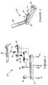
- an installation tool 40 is provided according to one embodiment of the present invention to facilitate mounting of the fiber optic connector upon the end portions of the optical field fibers.
- Figures 2 and 3 depict an exploded perspective view and an assembled perspective view, respectively, of an installation tool.
- the installation tool typically includes a base 42. Mounted to the base, typically by means of set screws 44, are a fiber holder 46 for holding the optical field fibers, an anvil 48 for facilitating the crimping of crimp tube 24 during assembly of the fiber optic connector, and a tool housing 50.
- the installation tool also includes a wrench 52 mounted to the tool housing for engaging the cam member 20 of the fiber optic connector and permitting actuation thereof.
- the installation tool further includes an adapter 54 that is mounted within the tool housing and a bias member 57 that is also mounted within the tool housing for securing the adapter in position therewithin.
- the adapter 54 has opposed first and second ends 56, 58 and defines a shoulder 60 therebetween.
- the first end of the adapter is designed to engage the fiber optic connector 10 that is being mounted upon the end portions of the optical field fibers.
- the first end of the adapter is designed to engage the housing 30 of the MT-RJ UNICAM connector, such as by being sized and shaped to receive the housing of the MT-RJ UNICAM connector and defining windows for receiving and engaging corresponding tabs that extend outwardly from the housing.
- the installation tool 40 includes first and second adapters 54 that can be alternately mounted within the tool housing 50 to configure the installation tool to have first and second configurations, respectively.
- the second end 58 of the first adapter is also sized and shaped to engage another fiber optic connector, typically of the same type engaged by the first end 56 of the adapter.
- the fiber optic connector engaged by the second end of the first adapter is mounted upon the end portion of an optical fiber that serves to deliver light for testing the continuity of the optical fiber stubs and the optical field fibers.
- first and second ends of the first adapter are both typically designed to engage the same type of fiber optic connectors
- first and second ends of the first adapter are preferably sized differently so as to thereby define a shoulder 60 that can be engaged by the bias member 57.
- the second adapter is of a more conventional design and has a closed second end that functions as a dust cap. Since the second end of the second adapter is not designed to engage another fiber optic connector, the second adapter is generally smaller than the first adapter.
- the installation tool 40 of the present invention can be differently configured depending upon its application.
- the first adapter can be mounted within the tool housing 50 in order to facilitate continuity testing of the optical fiber stubs and the optical field fibers while the fiber optic connector 10 is mounted within the installation tool as will be described in more detail hereinafter.
- the installation tool of the present invention can operate in a more conventional manner by facilitating the mounting of the fiber optic connector upon the end portions of the optical field fibers without permitting continuity testing of the optical fiber stubs and the optical field fibers.
- the second adapter could be used if the light source is attached to the optical field fibers rather than the optical fiber stubs.
- the installation tool 40 of the present invention also generally provides first and second bias members 57 adapted to engage the first and second adapters, respectively.
- each bias member generally has a U-shape and defines a channel 67 through which the respective adapter extends.
- the channel defined by the first bias member is preferably larger than the channel defined by the second bias member since the first adapter is also generally larger than the second adapter.
- Each bias member 57 includes a slide member 62 capable of being mounted within the tool housing 50 and a biasing element 64 for urging the respective slide member into engagement with the shoulder 60 defined by the respective adapter 54.
- each slide member typically includes an engagement portion 66 disposed within the tool housing for engaging the shoulder of the respective adapter.
- the engagement portion is generally U-shaped and defines the channel through which the second end 58 of the respective adapter extends.
- Each slide member also includes a base portion 68 disposed on the opposite side of the tool housing from the engagement portion. In this regard, the base portion is typically disposed between the tool housing and the base 42.
- each slide member includes a removable connector 70 interconnecting the engagement portion and the base portion.
- the tool housing preferably defines a lengthwise extending slot 72.
- the removable connector can extend through the slot defined by the tool housing in order to connect the engagement portion and the base portion and can ride within the slot as the slide member moves lengthwise relative to the tool housing.
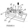
- the biasing element 64 typically engages the base portion 68 of each slide member 62 so as to bias or urge the slide member in a predetermined direction, such as to the right in Figure 4.
- the adapter 54 can be secured in position between an upstanding portion of the tool housing and the slide member.
- the slide member depicted in Figure 4 can be moved to the left by a technician and an adapter inserted between the slide member and an upstanding portion of the tool housing. Once the slide member is released by the technician, the biasing element urges the slide member to the right and into contact with the shoulder 60 of the adapter, thereby securing the adapter and connector housing 30 against the upstanding portion of the tool housing.
- the installation tool 40 can be readily converted between the first and second configurations without substantially disassembling the installation tool.
- the first adapter 54 is removed from the installation tool and the removable connector 70 is removed in order to disconnect the engagement portion 66 and the base portion 68.
- the engagement portion of the first bias member 57 is then replaced with the engagement portion of the second bias member and the removable connector is reinserted.
- the second adapter is inserted into the tool housing 50 to complete the reconfiguration process. By reversing these steps, the installation tool can also be easily converted from the second . configuration to the first configuration, if so desired.
- the installation tool need not be disassembled, such as by removing the tool housing, or any other component from the base 42 , in order to be reconfigured.
- the same installation tool can function as a conventional installation tool in the second configuration in which a dust cover is mounted to the fiber optic connector 10 that is being mounted upon the end portions of the optical field fibers and which does not support continuity testing while the fiber optic connector is mounted within the installation tool, as well as a modified installation tool in the first configuration which permits continuity testing to be performed while the fiber optic connector is mounted within the installation tool, as described in more detail below.
- the fiber optic connector 10 In order to test the continuity of the optical field fibers and the optical fiber stubs during the process of mounting a fiber optic connector 10 , such as a MT-RJ UNICAM® connector, upon the end portions of the optical field fibers, at least portions of the fiber optic connector are initially mounted within the installation tool 40 that is assembled to have the first configuration. See block 80 of Figure 6.
- the fiber optic connector with the exception of the crimp band 26 and the boot 36 are assembled and the forward end of the housing 30 is inserted into the first end 56 of the adapter 54 for engagement therewith. While the crimp band and the boot are not assembled to the remainder of the fiber optic connector, the crimp band and the boot are mounted upon the optical field fibers prior to inserting the optical field fibers into the fiber optic connector.
- the wrench 52 of the installation tool engages the cam member 20 of the fiber optic connector that has previously been mounted upon the ferrule holder 22.
- a light source such as a diode laser, for producing light signals having predetermined characteristics, such as a predetermined intensity and/or wavelength.
- the light produced by the light source is introduced into at least one of each pair of the optical fiber stubs and the optical field fibers. See block 82.
- the light is typically introduced into the optical fiber stubs.
- the light source can include a separate source for providing the light that is introduced into each optical fiber stub, a single light source is typically utilized with the light generated thereby being split prior to its introduction into the respective optical fiber stubs.
- the light produced by the light source is typically delivered to the optical fiber stubs by means of one or more optical fiber jumpers upon which a fiber optic connector is mounted.
- the fiber optic connector that is mounted upon the optical fiber jumpers from the light source is typically of the same type as the fiber optic connector 10 to be mounted upon the optical field fibers, such as an MT-RJ UNICAM® connector.
- the fiber optic connector associated with the optical fiber jumpers can therefore be inserted into the second end 58 of the adapter 54, i.e., the first adapter, such that light generated by the light source is introduced into each optical fiber stub of the fiber optic connector to be mounted to the optical field fibers.
- the light source could be introduced from the opposite end of the optical field fibers, rather than from the connector end. In this manner, the light would emanate from the ends of the optical field fibers rather than the optical fiber stubs. With the light emanating from the optical field fibers, either of the adapters 54 could be used.
- the optical field fibers are inserted into the rear end of the fiber optic connector 10 and advanced therethrough until contact is established with the respective optical fiber stubs. See block 84.
- the end portions of the optical field fibers are inserted through the crimp tube 24 and into respective grooves defined by the splice components. While the end portions of the optical field fibers are spaced apart from the optical fiber stubs, the light introduced into the optical fiber stubs generates a glow that emanates from the end portions of the optical fiber stubs within the splice components.
- the glow will dissipate since the light will be transmitted from the optical fiber stubs to respective optical field fibers.
- the glow emanating from the end portions of the optical fiber stubs is preferably monitored as the optical field fibers are advanced into the fiber optic connector since the glow provides an indication of optical continuity.
- at least one of the cam mechanism and the splice components of the multifiber connector is translucent.
- the multifiber connector of one advantageous embodiment includes a cam member 20 , a ferrule holder 22 and splice components that are each translucent to permit the technician to monitor the glow emanating from the end portions of each optical fiber stub.
- optical field fibers Once the optical field fibers appear to have made optical contact with the respective optical fiber stubs as indicated by the dissipation of the glow associated with each optical fiber stub, the optical field fibers are no longer advanced and the cam mechanism is actuated to secure the optical field fibers in position relative to the optical fiber stubs. See blocks 86 and 88.
- the cam mechanism is actuated by rotating the cam member 20 relative to the ferrule holder 22 which, in turn, actuates the splice components and forces the splice components together,
- the outwardly extending handle of the wrench 52 can be grasped by the technician and moved so as to rotate the cam member relative to the ferrule holder.
- the fiber optic connector 10 is evaluated to determine if the glow that previously emanated from the optical fiber stubs completely disappears, thereby indicating that the optical field fibers and the optical fiber stubs are continuous. See block 90. If the glow has not been extinguished and the continuity is therefore unacceptable, the cam mechanism is deactuated. See block 92.
- the cam member 20 of an MT-RJ UNICAM® connector can be rotated relative to the ferrule holder 22 in order to deactuate the splice components by returning the wrench 52 to its original position. Thereafter, the optical field fibers can be repositioned relative to the optical fiber stubs.
- the optical field fibers can be withdrawn from the fiber optic connector, recleaved and cleaned prior to being reinserted into the fiber optic connector and repositioned. See block 94 .
- the optical field fibers are generally cleaned of any index matching gel prior to being recleaved and thereafter recleaned with alcohol or the like.
- the glow emanating from the end portions of the optical fiber stubs is again monitored to determine when continuity appears to have been established between each of the optical field fibers and the optical fiber stubs.
- the cam mechanism can be reactuated to secure the optical field fibers in position relative to the optical fiber stubs.
- the fiber optic connector 10 can then again be inspected to determine if the glow has been completely extinguished.
- the repositioning and retesting of the continuity of the optical field fibers and the optical fiber stubs can be repeated as many times as necessary in order to obtain acceptable continuity between each pair of optical field fibers and optical fiber stubs.
- the fiber optic connector 10 can be physically secured to the optical field fibers.
- the crimp tube 24 is generally crimped about the optical fibers and, more commonly, about the buffer tubes.
- the installation tool can include an arm 78 pivotally connected to the tool housing. By rotating the arm downwardly, the crimp tube can be compressed between the underside of the arm and the anvil 48, thereby crimping the crimp tube radially inward about the ferrule holder and securing the strength members therebetween. See block 96.
- a crimp band 26 is then typically slid over the optical field fibers and the crimp tube and about the rear end of the ferrule holder 22 such that the strength members that extend lengthwise along with the optical field fibers are positioned between the crimp band and the ferrule holder. Once properly positioned, the crimp band is crimped radially inward so as to securely couple the strength members of the fiber optic cable and the fiber optic connector. See block 100. The boot 36 is then slid along the optical field fibers and inserted into the rear end of the housing so as to provide strain relief for the optical field fibers. See block 102.
- the continuity of the optical field fibers and the optical fiber stubs is confirmed by the extinguishment of the glow emanating from the optical fiber stubs, the continuity of the optical field fibers and the optical fiber stubs can be further and/or alternatively evaluated by an additional test.
- the fiber optic connector 10 is removed from the installation tool 40 after the cam mechanism has been actuated to secure the optical field fibers and the optical fiber stubs, but prior to crimping the crimp tube 24 about the optical fibers.
- the fiber optic connector is removed from the installation tool by disengaging the housing 30 and the adapter 54 from the slide member 62.
- the continuity of the optical field fibers and the optical fiber stubs can then be evaluated in a conventional manner.
- a power meter such as a JDS power meter
- a power meter can be connected to the fiber optic connector through adapter 54 (functioning as a regular connector adapter) in order to introduce light into each pair of optical fiber stubs and optical field fibers and to measure attenuation of the light, typically by measuring the insertion loss and the back reflectance. If the insertion loss is unacceptably high or if the back reflectance is unacceptably low, it will generally be determined that the optical fiber stubs and the optical field fibers are not sufficiently continuous. Alternatively, if the insertion loss is relatively low and the back reflectance is relatively high, the testing will confirm that optical field fibers and the optical fiber stubs are continuous.
- the fiber optic connector 10 is then remounted within the installation tool 40 such as by inserting the housing 30 at least partially within the first end 56 of the first adapter 54. If the continuity of the optical field fibers and the optical fiber stubs is unacceptable, the cam mechanism can be deactuated and the optical field fibers can be repositioned as described above and as shown in blocks 92 and 94. If the continuity of the optical field fibers and the optical fiber stubs is acceptable, however, the crimp tube 24 is crimped about the optical fibers prior to removing the fiber optic connector from the installation tool and completing the assembly process as also described above and depicted in blocks 96-102.
- a technician can visually determine when continuity appears to have been established between each of the optical field fibers and the respective optical fiber stubs.
- the continuity can be validated and, if it is determined that continuity has not actually been established between one or more of the optical field fibers and their respective optical fiber stubs, the cam mechanism can be deactuated, the optical field fibers can be repositioned, the cam mechanism reactuated and the process repeated until continuity is confirmed between each optical field fiber and the respective optical fiber stub.
- the method and associated multifiber connector and installation tool 40 of the present invention reduce the time required to mount fiber optic connectors upon optical field fibers in the field and to test the continuity of the resulting optical connection.
- the method and the associated multifiber connector and installation tool of the present invention reduce the number of fiber optic connectors that must be scrapped, thereby reducing the overall costs associated with the connectorization of optical field fibers in the field.
Landscapes
- Physics & Mathematics (AREA)
- General Physics & Mathematics (AREA)
- Optics & Photonics (AREA)
- Engineering & Computer Science (AREA)
- Civil Engineering (AREA)
- Structural Engineering (AREA)
- Mechanical Coupling Of Light Guides (AREA)
Applications Claiming Priority (2)
| Application Number | Priority Date | Filing Date | Title |
|---|---|---|---|
| US532722 | 2000-03-22 | ||
| US09/532,722 US6816661B1 (en) | 2000-03-22 | 2000-03-22 | Multifiber connector, installation tool and associated methods of validating optical fiber continuity |
Publications (1)
| Publication Number | Publication Date |
|---|---|
| EP1136860A2 true EP1136860A2 (fr) | 2001-09-26 |
Family
ID=24122880
Family Applications (1)
| Application Number | Title | Priority Date | Filing Date |
|---|---|---|---|
| EP20010107178 Withdrawn EP1136860A2 (fr) | 2000-03-22 | 2001-03-22 | Connecteur multifibre, outil d'installation et méthodes associées pour validation de la continuité d'une fibre optique |
Country Status (2)
| Country | Link |
|---|---|
| US (5) | US6816661B1 (fr) |
| EP (1) | EP1136860A2 (fr) |
Cited By (12)
| Publication number | Priority date | Publication date | Assignee | Title |
|---|---|---|---|---|
| WO2005096050A3 (fr) * | 2004-03-24 | 2006-02-16 | Corning Cable Sys Llc | Connecteur a fibres optiques pouvant etre monte en usine |
| US7011454B2 (en) | 2003-08-25 | 2006-03-14 | Panduit Corp. | Reversible fiber optic stub fiber connector |
| WO2007078551A2 (fr) | 2005-12-15 | 2007-07-12 | Corning Cable Systems Llc | Appareil et procédés servant à contrôler qu'une terminaison d'epissure est acceptable |
| WO2007089432A1 (fr) * | 2006-01-26 | 2007-08-09 | Corning Cable Systems Llc | Outil d'installation équipé d'un indicateur d'erreur visuel intégré pour raccord mécanique montable sur place |
| EP1868018A2 (fr) | 2006-06-13 | 2007-12-19 | Panduit Corporation | Outil d'activation pour un connecteur de fibre optique |
| JP2007334353A (ja) * | 2006-06-13 | 2007-12-27 | Panduit Corp | 可逆的光ファイバコネクタ |
| EP2259110A2 (fr) | 2004-11-04 | 2010-12-08 | Panduit Corporation | Un assemblage de connecteur optique LC et un outil de terminaison à came |
| WO2011025637A1 (fr) * | 2009-08-31 | 2011-03-03 | Corning Cable Systems Llc | Outil de raccordement et procédés associés |
| WO2013152106A1 (fr) * | 2012-04-05 | 2013-10-10 | Corning Cable Systems Llc | Outil d'installation de fibre optique ayant un élément d'éclairage passif |
| CN103703398A (zh) * | 2011-05-25 | 2014-04-02 | 泰科电子公司 | 无需工具的夹持机构 |
| US8981961B2 (en) | 2013-01-21 | 2015-03-17 | International Business Machines Corporation | Validation of mechanical connections |
| US10790645B1 (en) * | 2016-04-04 | 2020-09-29 | Andrew Scott Long | Tool for removing a splice from a power line |
Families Citing this family (113)
| Publication number | Priority date | Publication date | Assignee | Title |
|---|---|---|---|---|
| AU6255101A (en) | 2000-06-12 | 2001-12-24 | Krone Gmbh | Assembly and method for use in terminating an optical fibre or fibres |
| US20060115219A1 (en) * | 2004-11-29 | 2006-06-01 | Mudd Ronald L | Optical fiber connector |
| CA2531263C (fr) * | 2004-12-22 | 2015-11-03 | Tyco Electronics Corporation | Appareil de raccordement de fibres optiques, elements d'etancheification de l'entree et methodes d'utilisation connexes |
| US7359613B2 (en) * | 2005-05-27 | 2008-04-15 | Tyco Electronics Corporation | Optical fiber termination apparatus for taut sheath splicing and method for using the same |
| US8054314B2 (en) | 2005-05-27 | 2011-11-08 | Ati Technologies, Inc. | Applying non-homogeneous properties to multiple video processing units (VPUs) |
| US7356237B2 (en) * | 2005-07-25 | 2008-04-08 | Tyco Electronics Corporation | Optical fiber cable termination apparatus |
| US7192195B2 (en) | 2005-07-29 | 2007-03-20 | Corning Cable Systems Llc | Methods and apparatus for estimating optical insertion loss |
| JP3987078B2 (ja) * | 2005-08-31 | 2007-10-03 | 日本電信電話株式会社 | 光コネクタ |
| WO2007050470A1 (fr) * | 2005-10-24 | 2007-05-03 | 3M Innovative Properties Company | Connecteur optique, unité de distribution de fibres, et plate-forme de terminaison de fibres pour connecteurs optiques |
| JP4942327B2 (ja) * | 2005-10-28 | 2012-05-30 | スリーエム イノベイティブ プロパティズ カンパニー | 光コネクタ |
| JP4660351B2 (ja) * | 2005-10-31 | 2011-03-30 | スリーエム イノベイティブ プロパティズ カンパニー | 光コネクタ |
| US20070133926A1 (en) * | 2005-12-13 | 2007-06-14 | Semmler Scott E | Flexible cam member for fiber optic mechanical splice connector |
| CA2633301A1 (fr) * | 2005-12-16 | 2007-06-21 | Exfo Electro-Optical Engineering Inc. | Estimation de la perte d'epissures mecaniques connectant des fibres optiques entre elles et outil d'installation de connecteur |
| US7329049B2 (en) * | 2005-12-27 | 2008-02-12 | Corning Cable Systems Llc | Splice connector for verifying an acceptable splice termination |
| US7194179B1 (en) * | 2005-12-27 | 2007-03-20 | 3M Innovative Properties Company | Assembly tool and optical connector assembly method |
| US7756372B2 (en) * | 2006-02-22 | 2010-07-13 | Tyco Electronics Corporation | Fiber optic cable systems and kits and methods for terminating the same |
| US7658553B2 (en) * | 2006-03-14 | 2010-02-09 | Corning Cable Systems Llc | Mechanical splice connector with sequential splice and strain relief |
| US7264410B1 (en) * | 2006-03-16 | 2007-09-04 | Corning Cable Systems Llc | Dual function splice component for mechanical splice connector |
| US7572064B2 (en) * | 2006-07-24 | 2009-08-11 | Corning Cable Systems Llc | Optical fiber mechanical splice connector |
| US20080085090A1 (en) * | 2006-10-10 | 2008-04-10 | Meek David W | Crimp and crimp mechanism for fiber optic connector |
| KR100846740B1 (ko) * | 2006-12-13 | 2008-07-17 | 노바옵틱스 (주) | 광커넥터 조립장치 |
| US7520677B2 (en) * | 2007-01-12 | 2009-04-21 | Corning Cable Systems Llc | Non-physical contact visual fault locator coupler |
| US7668432B2 (en) * | 2007-01-31 | 2010-02-23 | Tyco Electronics Corporation | Multi-drop closure systems and methods for fiber optic cabling |
| US7467899B2 (en) | 2007-01-31 | 2008-12-23 | The Furukawa Electric Co., Ltd. | Ferrule transfer method and ferrule holder |
| US7435009B1 (en) | 2007-05-21 | 2008-10-14 | At&T Intellectual Property I, L.P. | Optical fiber connection system |
| US8798427B2 (en) | 2007-09-05 | 2014-08-05 | Corning Cable Systems Llc | Fiber optic terminal assembly |
| ES2567083T3 (es) * | 2008-04-25 | 2016-04-19 | 3M Innovative Properties Company | Conector óptico de formato LC terminable en el campo con elemento de empalme |
| EP2344915A4 (fr) * | 2008-10-09 | 2015-01-21 | Corning Cable Sys Llc | Terminal à fibre optique ayant un panneau adaptateur portant à la fois les fibres d'entrée et de sortie provenant d'un diviseur optique |
| US8879882B2 (en) | 2008-10-27 | 2014-11-04 | Corning Cable Systems Llc | Variably configurable and modular local convergence point |
| US20100124394A1 (en) * | 2008-11-19 | 2010-05-20 | David Wayne Meek | Process for connecting fibers and connected optical assembly |
| US9459783B2 (en) | 2009-01-09 | 2016-10-04 | Hillcrest Laboratories, Inc. | Zooming and panning widget for internet browsers |
| JP2012515936A (ja) | 2009-01-19 | 2012-07-12 | コーニング ケーブル システムズ リミテッド ライアビリティ カンパニー | 光ファイバ接続のための成端システム |
| WO2010104611A1 (fr) | 2009-03-11 | 2010-09-16 | Exxonmobil Chemical Patents Inc. | Revêtements intérieurs de pneus dotés de propriétés améliorées aux températures froides |
| US8646989B2 (en) | 2009-05-19 | 2014-02-11 | Adc Telecommunications, Inc. | Mechanical interface between a fiber optic cable and a fiber optic connector |
| USD619100S1 (en) | 2009-10-21 | 2010-07-06 | 3M Innovative Properties Company | Latch for an optical fiber connector |
| WO2011087944A1 (fr) | 2010-01-15 | 2011-07-21 | Corning Cable Systems Llc | Connecteur de fibre optique d'un système de terminaison de connexion par fibre optique |
| EP2354824A1 (fr) * | 2010-01-29 | 2011-08-10 | CCS Technology Inc. | Connecteur hybride |
| CN102906613A (zh) | 2010-03-10 | 2013-01-30 | 康宁光缆系统有限公司 | 允许单/多路接头的光纤尾端组件 |
| US9547144B2 (en) | 2010-03-16 | 2017-01-17 | Corning Optical Communications LLC | Fiber optic distribution network for multiple dwelling units |
| US8792767B2 (en) | 2010-04-16 | 2014-07-29 | Ccs Technology, Inc. | Distribution device |
| AU2011317244A1 (en) | 2010-10-19 | 2013-05-23 | Corning Cable Systems Llc | Transition box for multiple dwelling unit fiber optic distribution network |
| CN203825234U (zh) | 2010-11-30 | 2014-09-10 | 康宁光缆系统有限责任公司 | 可现场组装的机械接合连接器 |
| US9052468B2 (en) * | 2011-03-04 | 2015-06-09 | Corning Cable Systems Llc | Fiber optic adapter mount |
| US8639082B2 (en) * | 2011-04-19 | 2014-01-28 | Tyco Electronics Corporation | Fiber optic cable assembly |
| US8876405B2 (en) | 2011-06-27 | 2014-11-04 | 3M Innovative Properties Company | Field terminable optical connector with splice element for jacketed cable |
| CN102854575B (zh) * | 2011-07-01 | 2016-04-06 | 泰科电子(上海)有限公司 | 光纤连接器 |
| US9110266B2 (en) | 2011-07-29 | 2015-08-18 | Corning Cable Systems Llc | Fiber optic cables seal and/or strain relief members, and related assemblies and methods |
| US9219546B2 (en) | 2011-12-12 | 2015-12-22 | Corning Optical Communications LLC | Extremely high frequency (EHF) distributed antenna systems, and related components and methods |
| US8842962B2 (en) | 2012-01-27 | 2014-09-23 | Corning Cable Systems Llc | Fiber optic cable strain relief device and method |
| US8692984B2 (en) | 2012-01-31 | 2014-04-08 | Fluke Corporation | Field tester for topologies utilizing array connectors and multi-wavelength field tester for topologies utilizing array connectors |
| US9103994B2 (en) | 2012-01-31 | 2015-08-11 | Corning Cable Systems Llc | Optical fiber guide apparatuses for splice connector installation tools, and related assemblies and methods |
| US20130195415A1 (en) | 2012-01-31 | 2013-08-01 | Brandon A. Barnes | Detachable optical fiber guides for splice connector installation tools, and related assemblies and methods |
| US8620123B2 (en) | 2012-02-13 | 2013-12-31 | Corning Cable Systems Llc | Visual tracer system for fiber optic cable |
| US10110307B2 (en) | 2012-03-02 | 2018-10-23 | Corning Optical Communications LLC | Optical network units (ONUs) for high bandwidth connectivity, and related components and methods |
| US9004778B2 (en) | 2012-06-29 | 2015-04-14 | Corning Cable Systems Llc | Indexable optical fiber connectors and optical fiber connector arrays |
| US9049500B2 (en) | 2012-08-31 | 2015-06-02 | Corning Cable Systems Llc | Fiber optic terminals, systems, and methods for network service management |
| US8909019B2 (en) | 2012-10-11 | 2014-12-09 | Ccs Technology, Inc. | System comprising a plurality of distribution devices and distribution device |
| HUE041644T2 (hu) | 2012-10-15 | 2019-05-28 | Corning Optical Communications LLC | Ragasztókészítmények beleértve részlegesen keresztkötött gyantákat és azok felhasználási eljárásait |
| US9568686B2 (en) | 2012-10-15 | 2017-02-14 | Corning Optical Communications LLC | Optical connector and ferrule adhesion system including adhesive composition, and related methods |
| EP2725396B1 (fr) | 2012-10-26 | 2016-09-14 | CCS Technology, Inc. | Dispositif de réduction de tension et dispositif de distribution à fibres optiques |
| JP6235124B2 (ja) * | 2013-05-03 | 2017-11-22 | モレックス エルエルシー | 光ファイバーアセンブリ |
| US8702322B1 (en) | 2013-06-03 | 2014-04-22 | Corning Cable Systems Llc | Optical connector with adhesive material |
| US9588303B2 (en) | 2013-06-03 | 2017-03-07 | Corning Optical Communications LLC | Optical connector with adhesive material |
| US9429731B2 (en) | 2013-08-12 | 2016-08-30 | Corning Optical Communications LLC | Optical fiber cable assembly comprising optical tracer fiber |
| US20150063756A1 (en) * | 2013-08-29 | 2015-03-05 | Coring Cable Systems Llc | System for terminating one or more optical fibers and fiber optic connector holder used in same |
| WO2015031655A1 (fr) * | 2013-08-29 | 2015-03-05 | Adc Telecommunications, Inc. | Test de performances de fibres optiques dans le champ |
| US9488793B2 (en) | 2013-09-10 | 2016-11-08 | Corning Optical Communications LLC | Combined optical fiber and power cable |
| US9086548B2 (en) | 2013-09-30 | 2015-07-21 | Corning Cable Systems Llc | Optical connectors with inorganic adhesives and methods for making the same |
| US10379309B2 (en) | 2014-11-18 | 2019-08-13 | Corning Optical Communications LLC | Traceable optical fiber cable and filtered viewing device for enhanced traceability |
| US9304278B1 (en) | 2015-03-31 | 2016-04-05 | Corning Optical Communications LLC | Traceable cable with side-emitting optical fiber and method of forming the same |
| US10228526B2 (en) | 2015-03-31 | 2019-03-12 | Corning Optical Communications LLC | Traceable cable with side-emitting optical fiber and method of forming the same |
| US10101553B2 (en) | 2015-05-20 | 2018-10-16 | Corning Optical Communications LLC | Traceable cable with side-emitting optical fiber and method of forming the same |
| CN107850737A (zh) | 2015-07-17 | 2018-03-27 | 康宁光电通信有限责任公司 | 用于跟踪电缆的系统和方法以及用于此类系统和方法的电缆 |
| EP3325876A1 (fr) | 2015-07-17 | 2018-05-30 | Corning Optical Communications LLC | Systèmes et procédés pour câbles traçables |
| US10101545B2 (en) | 2015-10-30 | 2018-10-16 | Corning Optical Communications LLC | Traceable cable assembly and connector |
| WO2017176825A1 (fr) | 2016-04-08 | 2017-10-12 | Corning Optical Communications LLC | Ensemble de câble à point d'extrémité traçable |
| US10107983B2 (en) | 2016-04-29 | 2018-10-23 | Corning Optical Communications LLC | Preferential mode coupling for enhanced traceable patch cord performance |
| US10295771B2 (en) | 2016-05-03 | 2019-05-21 | Corning Optical Communications LLC | Telecommunications terminal with removable modules |
| JP7084910B2 (ja) | 2016-07-21 | 2022-06-15 | ザ・シーモン・カンパニー | 光ファイバ成端工具 |
| US10984519B2 (en) | 2016-08-03 | 2021-04-20 | Panduit Corp. | Method for evaluating the optical insertion loss of a mechanical splice joint of two optical fibers |
| US10317314B2 (en) | 2016-08-23 | 2019-06-11 | Panduit Corp. | Fiber optic connector termination tool |
| US10222561B2 (en) | 2016-12-21 | 2019-03-05 | Corning Research & Development Corporation | Light launch device for transmitting light into a traceable fiber optic cable assembly with tracing optical fibers |
| US10234614B2 (en) | 2017-01-20 | 2019-03-19 | Corning Research & Development Corporation | Light source assemblies and systems and methods with mode homogenization |
| USD856280S1 (en) | 2017-05-25 | 2019-08-13 | Panduit Corp. | Termination tool |
| US12271040B2 (en) | 2017-06-28 | 2025-04-08 | Corning Research & Development Corporation | Fiber optic extender ports, assemblies and methods of making the same |
| US10359577B2 (en) | 2017-06-28 | 2019-07-23 | Corning Research & Development Corporation | Multiports and optical connectors with rotationally discrete locking and keying features |
| US11668890B2 (en) | 2017-06-28 | 2023-06-06 | Corning Research & Development Corporation | Multiports and other devices having optical connection ports with securing features and methods of making the same |
| EP3646092B1 (fr) | 2017-06-28 | 2021-11-24 | Corning Research & Development Corporation | Connecteurs de fibres optiques compacts |
| US11187859B2 (en) | 2017-06-28 | 2021-11-30 | Corning Research & Development Corporation | Fiber optic connectors and methods of making the same |
| USD846414S1 (en) | 2017-06-28 | 2019-04-23 | Panduit Corp. | Fiber connector termination tool |
| US11300746B2 (en) | 2017-06-28 | 2022-04-12 | Corning Research & Development Corporation | Fiber optic port module inserts, assemblies and methods of making the same |
| US10514511B2 (en) | 2017-11-02 | 2019-12-24 | Panduit Corp. | Optical fiber termination using a reference source |
| US10539747B2 (en) | 2017-12-05 | 2020-01-21 | Corning Research & Development Corporation | Bend induced light scattering fiber and cable assemblies and method of making |
| US10539758B2 (en) | 2017-12-05 | 2020-01-21 | Corning Research & Development Corporation | Traceable fiber optic cable assembly with indication of polarity |
| MX2021006211A (es) | 2018-11-29 | 2021-08-11 | Corning Res & Dev Corp | Multipuertos y otros dispositivos que tienen puertos de conexion optica con accionadores giratorios y metodos de fabricacion de los mismos. |
| HRP20241645T1 (hr) | 2018-12-28 | 2025-02-14 | Corning Research & Development Corporation | Sklopovi s više priključaka koji uključuju značajke za montažu ili čepove za prašinu |
| US10908364B2 (en) | 2019-02-08 | 2021-02-02 | Corning Research & Development Corporation | Fiber optic connectors with at least one field-installable termini |
| MX2021014427A (es) | 2019-05-31 | 2022-03-04 | Corning Res & Dev Corp | Multipuertos y otros dispositivos que tienen puertos de conexion optica con accionadores deslizantes y metodos para elaborar los mismos. |
| US11294133B2 (en) | 2019-07-31 | 2022-04-05 | Corning Research & Development Corporation | Fiber optic networks using multiports and cable assemblies with cable-to-connector orientation |
| US11079553B2 (en) | 2019-08-22 | 2021-08-03 | Cotsworks, Llc | Field installable rugged optical terminus |
| US11487073B2 (en) | 2019-09-30 | 2022-11-01 | Corning Research & Development Corporation | Cable input devices having an integrated locking feature and assemblies using the cable input devices |
| EP3805827B1 (fr) | 2019-10-07 | 2025-07-30 | Corning Research & Development Corporation | Terminaux à fibres optiques et réseaux à fibres optiques ayant des coupleurs à rapport variable |
| EP4045957B1 (fr) | 2019-10-18 | 2023-12-13 | Corning Research & Development Corporation | Multiports ayant des ports de connexion optiques avec des éléments de fixation fournissant des forces de retenue stables |
| US11650388B2 (en) | 2019-11-14 | 2023-05-16 | Corning Research & Development Corporation | Fiber optic networks having a self-supporting optical terminal and methods of installing the optical terminal |
| US11536921B2 (en) | 2020-02-11 | 2022-12-27 | Corning Research & Development Corporation | Fiber optic terminals having one or more loopback assemblies |
| CA3184578A1 (fr) | 2020-06-29 | 2022-01-06 | Michael De Jong | Bornes ayant un orifice de connexion optique multifibre qui empeche un endommagement a partir de connecteurs a monofibre |
| US11604320B2 (en) | 2020-09-30 | 2023-03-14 | Corning Research & Development Corporation | Connector assemblies for telecommunication enclosures |
| CN116601834A (zh) | 2020-10-30 | 2023-08-15 | 康宁研究与开发公司 | 具有防风雨套环的光纤连接器 |
| US11880076B2 (en) | 2020-11-30 | 2024-01-23 | Corning Research & Development Corporation | Fiber optic adapter assemblies including a conversion housing and a release housing |
| US11686913B2 (en) | 2020-11-30 | 2023-06-27 | Corning Research & Development Corporation | Fiber optic cable assemblies and connector assemblies having a crimp ring and crimp body and methods of fabricating the same |
| US11994722B2 (en) | 2020-11-30 | 2024-05-28 | Corning Research & Development Corporation | Fiber optic adapter assemblies including an adapter housing and a locking housing |
| US11927810B2 (en) | 2020-11-30 | 2024-03-12 | Corning Research & Development Corporation | Fiber optic adapter assemblies including a conversion housing and a release member |
| US11947167B2 (en) | 2021-05-26 | 2024-04-02 | Corning Research & Development Corporation | Fiber optic terminals and tools and methods for adjusting a split ratio of a fiber optic terminal |
Family Cites Families (44)
| Publication number | Priority date | Publication date | Assignee | Title |
|---|---|---|---|---|
| JPS5244207B2 (fr) | 1974-07-17 | 1977-11-05 | ||
| US4257674A (en) | 1979-04-23 | 1981-03-24 | Gte Products Corporation | Elastomeric fiber optic splice |
| US4621754A (en) * | 1983-01-03 | 1986-11-11 | Switchcraft, Inc. | Tool and method for cleaving optical fibers |
| FR2582048B1 (fr) | 1985-05-15 | 1988-09-16 | Elf Aquitaine | Dispositif de commande et de surveillance d'une tete de puits immergee dans un liquide |
| FR2593294B1 (fr) | 1986-01-23 | 1990-01-05 | Alsthom Cgee | Connecteur pour fibres optiques |
| US4964688A (en) | 1988-09-22 | 1990-10-23 | Northern Telecom Limited | Fiber optic connector element and method for its use |
| US4877303A (en) | 1988-09-22 | 1989-10-31 | Northern Telecom Limited | Fiber optic connector element & method for its use |
| US4923274A (en) | 1989-06-26 | 1990-05-08 | Siecor Corporation | Connector for optical fibers |
| US5125549A (en) * | 1990-01-25 | 1992-06-30 | E. I. Du Pont De Nemours And Company | Method and apparatus for scoring and breaking an optical fiber |
| US5040867A (en) | 1990-03-21 | 1991-08-20 | Siecor Corporation | Slide fit optical connector having end cap to prevent rotation |
| US5077880A (en) * | 1990-12-21 | 1992-01-07 | Siecor Corporation | Tool for closing optical connectors having locking rings |
| US5261020A (en) * | 1992-11-05 | 1993-11-09 | Siecor Corporation | Optical fiber connector assembly tool |
| CA2110940C (fr) | 1993-12-08 | 1998-08-18 | Kevin G. Caldwell | Epissure mecanique de fibres optiques |
| US5442724A (en) * | 1994-09-30 | 1995-08-15 | The Whitaker Corporation | Tool for terminating a fiber optic cable to a connector |
| US5720907A (en) * | 1995-04-24 | 1998-02-24 | Lucent Technologies Inc. | Method for manufacturing an optical connector assembly |
| US5555332A (en) * | 1995-06-08 | 1996-09-10 | Siecor Corporation | Applicator and associated method for inserting guide pins in a fiber optic connector |
| US5768409A (en) * | 1995-08-02 | 1998-06-16 | Lucent Technologies Inc. | Automatic inspection method for contactlessly measuring an offset of a central feature of an object |
| JP3778995B2 (ja) | 1996-06-28 | 2006-05-24 | 株式会社フジクラ | 光ファイバ調心構造 |
| JP3725210B2 (ja) | 1995-08-24 | 2005-12-07 | 株式会社フジクラ | 光ファイバ接続器 |
| JP3784446B2 (ja) | 1996-01-22 | 2006-06-14 | 株式会社フジクラ | 光ファイバ接続器 |
| JP3813219B2 (ja) | 1995-11-30 | 2006-08-23 | 株式会社フジクラ | 光ファイバ接続器 |
| JP3813220B2 (ja) | 1995-12-14 | 2006-08-23 | 株式会社フジクラ | 開放ピース付き光ファイバ接続器および作業治具 |
| JP3725214B2 (ja) | 1995-09-21 | 2005-12-07 | 株式会社フジクラ | 光ファイバ接続器 |
| JP3725215B2 (ja) | 1995-09-29 | 2005-12-07 | 株式会社フジクラ | 光ファイバ接続器 |
| JP3751061B2 (ja) | 1996-01-22 | 2006-03-01 | 株式会社フジクラ | 光ファイバ接続器 |
| KR100442975B1 (ko) | 1995-08-24 | 2004-12-03 | 가부시끼가이샤 후지꾸라 | 광섬유접속기 |
| JP3620121B2 (ja) | 1995-10-31 | 2005-02-16 | 住友電気工業株式会社 | 光コネクタ及び組立方法 |
| US5731893A (en) * | 1996-02-21 | 1998-03-24 | Dominique; Jeffrey M. | Portable microscope for inspecting fiber optic cable |
| JP3540096B2 (ja) | 1996-05-30 | 2004-07-07 | 株式会社フジクラ | 光ファイバ接続器 |
| JP3515677B2 (ja) | 1996-10-09 | 2004-04-05 | 住友電気工業株式会社 | 光コネクタおよびその取付方法 |
| JP3515305B2 (ja) | 1997-01-16 | 2004-04-05 | 株式会社フジクラ | 光コネクタ |
| US5724127A (en) * | 1997-02-27 | 1998-03-03 | Ciena Corporation | System and method for inspecting an end of a fiber optic |
| US5813902A (en) * | 1997-04-14 | 1998-09-29 | Minnesota Mining And Manufacturing Company | Optical fiber end-face preparation and connector assembly |
| US5940561A (en) * | 1997-04-23 | 1999-08-17 | Siecor Corporation | Adapter assembly for precise alignment of fiber optic connectors |
| US6022150A (en) * | 1997-04-30 | 2000-02-08 | The Whitaker Corporation | Fiber optic connector |
| JP3602339B2 (ja) | 1997-06-16 | 2004-12-15 | 株式会社フジクラ | 光コネクタ |
| TW493093B (en) | 1997-06-16 | 2002-07-01 | Fujikura Ltd | Optical connector |
| US5915055A (en) * | 1997-06-30 | 1999-06-22 | Siecor Corporation | Method and apparatus for connectorizing fiber optic cable |
| US6173097B1 (en) * | 1998-07-01 | 2001-01-09 | Siecor Operations, Llc | Field installable multifiber connector |
| US6210045B1 (en) * | 1998-12-29 | 2001-04-03 | Siecor Operations, Llc | Alignment sleeve for aligning ferrules and associated assembly method |
| GB9912089D0 (en) | 1999-05-25 | 1999-07-28 | British Nuclear Fuels Plc | A container for nuclear fuel elements |
| US6238101B1 (en) * | 1999-07-08 | 2001-05-29 | Molex Incorporated | Tunable fiber optic connector |
| US6442318B1 (en) * | 1999-11-23 | 2002-08-27 | Schott Fiber Optics, Inc. | Prefabricated optical fiber ribbon cable for connectorizing with a terminal connector and methods of connectorizing and fabricating the same |
| US6439780B1 (en) | 2000-08-31 | 2002-08-27 | Corning Cable Systems Llc | Field-installable fiber optic ribbon connector and installation tool |
-
2000
- 2000-03-22 US US09/532,722 patent/US6816661B1/en not_active Ceased
-
2001
- 2001-03-22 EP EP20010107178 patent/EP1136860A2/fr not_active Withdrawn
-
2004
- 2004-09-13 US US10/939,715 patent/US6931193B2/en not_active Expired - Lifetime
-
2005
- 2005-11-30 US US11/291,018 patent/USRE42094E1/en not_active Ceased
-
2012
- 2012-07-10 US US13/545,804 patent/USRE45482E1/en not_active Expired - Lifetime
-
2015
- 2015-01-29 US US14/609,136 patent/USRE46270E1/en not_active Expired - Lifetime
Cited By (41)
| Publication number | Priority date | Publication date | Assignee | Title |
|---|---|---|---|---|
| US8702324B2 (en) | 2003-08-25 | 2014-04-22 | Panduit Corp. | Reversible fiber optic stub clamping mechanism |
| US7011454B2 (en) | 2003-08-25 | 2006-03-14 | Panduit Corp. | Reversible fiber optic stub fiber connector |
| US7722262B2 (en) | 2003-08-25 | 2010-05-25 | Panduit Corp. | Reversible fiber optic stub clamping mechanism |
| US8256971B2 (en) | 2003-08-25 | 2012-09-04 | Panduit Corp. | Reversible fiber optic stub clamping mechanism |
| US9274286B2 (en) | 2003-08-25 | 2016-03-01 | Panduit Corp. | Reversible fiber optic stub clamping mechanism |
| US7568845B2 (en) | 2003-08-25 | 2009-08-04 | Panduit Corp. | Reversible fiber optic stub clamping mechanism |
| AU2011200715B2 (en) * | 2004-03-24 | 2012-09-06 | Corning Cable Systems Llc | Optical fiber connector and method |
| AU2005228025B2 (en) * | 2004-03-24 | 2011-03-17 | Corning Cable Systems Llc | Field installable optical fiber connector |
| CN100501473C (zh) * | 2004-03-24 | 2009-06-17 | 康宁光缆系统有限责任公司 | 可现场安装的光纤连接器 |
| WO2005096050A3 (fr) * | 2004-03-24 | 2006-02-16 | Corning Cable Sys Llc | Connecteur a fibres optiques pouvant etre monte en usine |
| CN101504475A (zh) * | 2004-03-24 | 2009-08-12 | 康宁光缆系统有限责任公司 | 光纤连接器 |
| US7104702B2 (en) | 2004-03-24 | 2006-09-12 | Corning Cable Systems Llc | Field installable optical fiber connector |
| EP1655627B1 (fr) * | 2004-11-04 | 2011-10-26 | Panduit Corporation | Un assemblage de connecteur optique LC et un outil de terminaison à came |
| EP2259110A3 (fr) * | 2004-11-04 | 2011-04-13 | Panduit Corporation | Un assemblage de connecteur optique LC et un outil de terminaison à came |
| EP2259110A2 (fr) | 2004-11-04 | 2010-12-08 | Panduit Corporation | Un assemblage de connecteur optique LC et un outil de terminaison à came |
| EP1960815A4 (fr) * | 2005-12-15 | 2013-03-27 | Corning Cable Sys Llc | Appareil et procédés servant à contrôler qu'une terminaison d'epissure est acceptable |
| EP2940498A1 (fr) * | 2005-12-15 | 2015-11-04 | Corning Cable Systems LLC | Appareil et procédés pour vérifier un raccordement de joint acceptable |
| WO2007078551A2 (fr) | 2005-12-15 | 2007-07-12 | Corning Cable Systems Llc | Appareil et procédés servant à contrôler qu'une terminaison d'epissure est acceptable |
| US8094988B2 (en) | 2005-12-15 | 2012-01-10 | Corning Cable Systems Llc | Apparatus and methods for verifying an acceptable splice termination |
| JP2009524848A (ja) * | 2006-01-26 | 2009-07-02 | コーニング ケーブル システムズ リミテッド ライアビリティ カンパニー | 現場取付け可能なメカニカルスプライス型コネクタ用一体形視覚的障害点測定器付き取付け工具 |
| AU2007210221B2 (en) * | 2006-01-26 | 2013-05-23 | Corning Cable Systems Llc | Installation tool with integrated visual fault indicator for field-installable mechanical splice connector |
| EP2259112A1 (fr) * | 2006-01-26 | 2010-12-08 | Corning Cable Systems LLC | Outil d'installation équipé d'un indicateur d'erreur visuel intégré pour raccord mécanique montable sur place |
| WO2007089432A1 (fr) * | 2006-01-26 | 2007-08-09 | Corning Cable Systems Llc | Outil d'installation équipé d'un indicateur d'erreur visuel intégré pour raccord mécanique montable sur place |
| US8718433B2 (en) | 2006-01-26 | 2014-05-06 | Corning Cable Systems Llc | Installation tool with integrated visual fault indicator for field-installable mechanical splice connector |
| US7680384B2 (en) | 2006-01-26 | 2010-03-16 | Corning Cable Systems Llc | Installation tool with integrated visual fault indicator for field-installable mechanical splice connector |
| JP2007334354A (ja) * | 2006-06-13 | 2007-12-27 | Panduit Corp | 光ファイバコネクタ用の作動工具 |
| US7466891B2 (en) | 2006-06-13 | 2008-12-16 | Panduit Corp. | Activation tool for a fiber optic connector |
| JP2012226376A (ja) * | 2006-06-13 | 2012-11-15 | Panduit Corp | 可逆成端可能な光ファイバコネクタ |
| EP1868018A2 (fr) | 2006-06-13 | 2007-12-19 | Panduit Corporation | Outil d'activation pour un connecteur de fibre optique |
| US7639917B2 (en) | 2006-06-13 | 2009-12-29 | Panduit Corp. | Activation tool for a fiber optic connector |
| JP2007334353A (ja) * | 2006-06-13 | 2007-12-27 | Panduit Corp | 可逆的光ファイバコネクタ |
| EP1868018A3 (fr) * | 2006-06-13 | 2010-06-23 | Panduit Corporation | Outil d'activation pour un connecteur de fibre optique |
| US8005336B2 (en) | 2006-06-13 | 2011-08-23 | Panduit Corp. | Activation tool for a fiber optic connector |
| WO2011025637A1 (fr) * | 2009-08-31 | 2011-03-03 | Corning Cable Systems Llc | Outil de raccordement et procédés associés |
| CN103703398A (zh) * | 2011-05-25 | 2014-04-02 | 泰科电子公司 | 无需工具的夹持机构 |
| CN103703398B (zh) * | 2011-05-25 | 2015-11-25 | 泰科电子公司 | 无需工具的夹持机构 |
| WO2013152106A1 (fr) * | 2012-04-05 | 2013-10-10 | Corning Cable Systems Llc | Outil d'installation de fibre optique ayant un élément d'éclairage passif |
| US9004733B2 (en) | 2012-04-05 | 2015-04-14 | Corning Cable Systems Llc | Optical fiber installation tool having a passive illumination feature |
| US8981961B2 (en) | 2013-01-21 | 2015-03-17 | International Business Machines Corporation | Validation of mechanical connections |
| US9947204B2 (en) | 2013-01-21 | 2018-04-17 | International Business Machines Corporation | Validation of mechanical connections |
| US10790645B1 (en) * | 2016-04-04 | 2020-09-29 | Andrew Scott Long | Tool for removing a splice from a power line |
Also Published As
| Publication number | Publication date |
|---|---|
| USRE42094E1 (en) | 2011-02-01 |
| US6816661B1 (en) | 2004-11-09 |
| US6931193B2 (en) | 2005-08-16 |
| USRE46270E1 (en) | 2017-01-10 |
| US20050031285A1 (en) | 2005-02-10 |
| USRE45482E1 (en) | 2015-04-21 |
Similar Documents
| Publication | Publication Date | Title |
|---|---|---|
| US6816661B1 (en) | Multifiber connector, installation tool and associated methods of validating optical fiber continuity | |
| CA2635563C (fr) | Connecteur bout-a-bout pour verifier un raccordement de joint acceptable | |
| CN100485431C (zh) | 可现场安装的光纤连接器 | |
| EP1977279B1 (fr) | Outil d'installation équipé d'un indicateur d'erreur visuel intégré pour raccord mécanique montable sur place | |
| CN100501473C (zh) | 可现场安装的光纤连接器 | |
| JP5199883B2 (ja) | 許容スプライス成端接続を検証する装置及び方法 | |
| US20050249466A1 (en) | Single-use fiber optic cable | |
| WO2015031223A1 (fr) | Système d'essai pour vérifier une connexion par épissage entre un connecteur de fibre optique et une ou plusieurs fibres optiques | |
| US7192195B2 (en) | Methods and apparatus for estimating optical insertion loss | |
| CN100580492C (zh) | 用于光波导体插接连接器的内壳 | |
| JP6684461B2 (ja) | 光可視化フィルタ及びそれを用いた通信光可視化装置 | |
| WO2019043049A1 (fr) | Dispositif de serrage pour fibre optique | |
| JPH09197157A (ja) | 光ファイバ接続器および光ファイバの接続方法 | |
| JP2005115285A (ja) | 光ファイバ接続部材及び光ファイバ接続方法 | |
| MX2008007660A (es) | Aparato y metodos para verificar una terminacion de empalme aceptable |
Legal Events
| Date | Code | Title | Description |
|---|---|---|---|
| PUAI | Public reference made under article 153(3) epc to a published international application that has entered the european phase |
Free format text: ORIGINAL CODE: 0009012 |
|
| AK | Designated contracting states |
Kind code of ref document: A2 Designated state(s): AT BE CH CY DE DK ES FI FR GB GR IE IT LI LU MC NL PT SE TR |
|
| AX | Request for extension of the european patent |
Free format text: AL;LT;LV;MK;RO;SI |
|
| STAA | Information on the status of an ep patent application or granted ep patent |
Free format text: STATUS: THE APPLICATION IS DEEMED TO BE WITHDRAWN |
|
| 18D | Application deemed to be withdrawn |
Effective date: 20031001 |