EP1136747A1 - Eclairage encastrable dans un plafond en béton - Google Patents
Eclairage encastrable dans un plafond en béton Download PDFInfo
- Publication number
- EP1136747A1 EP1136747A1 EP00810244A EP00810244A EP1136747A1 EP 1136747 A1 EP1136747 A1 EP 1136747A1 EP 00810244 A EP00810244 A EP 00810244A EP 00810244 A EP00810244 A EP 00810244A EP 1136747 A1 EP1136747 A1 EP 1136747A1
- Authority
- EP
- European Patent Office
- Prior art keywords
- housing
- reflector
- opening
- lamp
- recessed
- Prior art date
- Legal status (The legal status is an assumption and is not a legal conclusion. Google has not performed a legal analysis and makes no representation as to the accuracy of the status listed.)
- Withdrawn
Links
Images


Classifications
-
- F—MECHANICAL ENGINEERING; LIGHTING; HEATING; WEAPONS; BLASTING
- F21—LIGHTING
- F21V—FUNCTIONAL FEATURES OR DETAILS OF LIGHTING DEVICES OR SYSTEMS THEREOF; STRUCTURAL COMBINATIONS OF LIGHTING DEVICES WITH OTHER ARTICLES, NOT OTHERWISE PROVIDED FOR
- F21V29/00—Protecting lighting devices from thermal damage; Cooling or heating arrangements specially adapted for lighting devices or systems
- F21V29/50—Cooling arrangements
- F21V29/70—Cooling arrangements characterised by passive heat-dissipating elements, e.g. heat-sinks
- F21V29/83—Cooling arrangements characterised by passive heat-dissipating elements, e.g. heat-sinks the elements having apertures, ducts or channels, e.g. heat radiation holes
-
- F—MECHANICAL ENGINEERING; LIGHTING; HEATING; WEAPONS; BLASTING
- F21—LIGHTING
- F21V—FUNCTIONAL FEATURES OR DETAILS OF LIGHTING DEVICES OR SYSTEMS THEREOF; STRUCTURAL COMBINATIONS OF LIGHTING DEVICES WITH OTHER ARTICLES, NOT OTHERWISE PROVIDED FOR
- F21V29/00—Protecting lighting devices from thermal damage; Cooling or heating arrangements specially adapted for lighting devices or systems
- F21V29/50—Cooling arrangements
- F21V29/60—Cooling arrangements characterised by the use of a forced flow of gas, e.g. air
-
- F—MECHANICAL ENGINEERING; LIGHTING; HEATING; WEAPONS; BLASTING
- F21—LIGHTING
- F21S—NON-PORTABLE LIGHTING DEVICES; SYSTEMS THEREOF; VEHICLE LIGHTING DEVICES SPECIALLY ADAPTED FOR VEHICLE EXTERIORS
- F21S8/00—Lighting devices intended for fixed installation
- F21S8/02—Lighting devices intended for fixed installation of recess-mounted type, e.g. downlighters
-
- F—MECHANICAL ENGINEERING; LIGHTING; HEATING; WEAPONS; BLASTING
- F21—LIGHTING
- F21V—FUNCTIONAL FEATURES OR DETAILS OF LIGHTING DEVICES OR SYSTEMS THEREOF; STRUCTURAL COMBINATIONS OF LIGHTING DEVICES WITH OTHER ARTICLES, NOT OTHERWISE PROVIDED FOR
- F21V15/00—Protecting lighting devices from damage
- F21V15/01—Housings, e.g. material or assembling of housing parts
-
- F—MECHANICAL ENGINEERING; LIGHTING; HEATING; WEAPONS; BLASTING
- F21—LIGHTING
- F21V—FUNCTIONAL FEATURES OR DETAILS OF LIGHTING DEVICES OR SYSTEMS THEREOF; STRUCTURAL COMBINATIONS OF LIGHTING DEVICES WITH OTHER ARTICLES, NOT OTHERWISE PROVIDED FOR
- F21V19/00—Fastening of light sources or lamp holders
- F21V19/0075—Fastening of light sources or lamp holders of tubular light sources, e.g. ring-shaped fluorescent light sources
- F21V19/0095—Fastening of light sources or lamp holders of tubular light sources, e.g. ring-shaped fluorescent light sources of U-shaped tubular light sources, e.g. compact fluorescent tubes
-
- F—MECHANICAL ENGINEERING; LIGHTING; HEATING; WEAPONS; BLASTING
- F21—LIGHTING
- F21V—FUNCTIONAL FEATURES OR DETAILS OF LIGHTING DEVICES OR SYSTEMS THEREOF; STRUCTURAL COMBINATIONS OF LIGHTING DEVICES WITH OTHER ARTICLES, NOT OTHERWISE PROVIDED FOR
- F21V21/00—Supporting, suspending, or attaching arrangements for lighting devices; Hand grips
- F21V21/02—Wall, ceiling, or floor bases; Fixing pendants or arms to the bases
- F21V21/04—Recessed bases
-
- F—MECHANICAL ENGINEERING; LIGHTING; HEATING; WEAPONS; BLASTING
- F21—LIGHTING
- F21V—FUNCTIONAL FEATURES OR DETAILS OF LIGHTING DEVICES OR SYSTEMS THEREOF; STRUCTURAL COMBINATIONS OF LIGHTING DEVICES WITH OTHER ARTICLES, NOT OTHERWISE PROVIDED FOR
- F21V23/00—Arrangement of electric circuit elements in or on lighting devices
- F21V23/02—Arrangement of electric circuit elements in or on lighting devices the elements being transformers, impedances or power supply units, e.g. a transformer with a rectifier
-
- F—MECHANICAL ENGINEERING; LIGHTING; HEATING; WEAPONS; BLASTING
- F21—LIGHTING
- F21Y—INDEXING SCHEME ASSOCIATED WITH SUBCLASSES F21K, F21L, F21S and F21V, RELATING TO THE FORM OR THE KIND OF THE LIGHT SOURCES OR OF THE COLOUR OF THE LIGHT EMITTED
- F21Y2103/00—Elongate light sources, e.g. fluorescent tubes
- F21Y2103/30—Elongate light sources, e.g. fluorescent tubes curved
- F21Y2103/37—U-shaped
Definitions
- the invention relates to a recessed light for a concrete ceiling.
- Such lights already require the manufacture of the concrete ceiling
- Appropriate measures so that the lamp is complete is integrated into the concrete ceiling, including the electrical Line pipes must be concreted in beforehand.
- Recessed luminaires of the same type are already available for Various types of lamps are known, but in particular for low-voltage halogen lamps.
- DE-U-91 02 903.1 describes a concrete installation pot, its open end by means of a cover plate can be closed with a circular opening.
- CH-A-687 564 a recessed light for halogen lamps is described in which the transformer and the lamp holder can be detached in one concreted housing are held and by the room side Lamp opening are removable from the housing.
- Ballasts have so far not been a satisfactory installation solution known.
- the lights are largely in hollow ceilings of rooms that are ventilated via the hollow ceiling.
- a common installation option for direct installation in Concrete ceilings consist of being relatively voluminous and always to pour in two parts of the existing, closed housing. This creates a cavity in the concrete ceiling that is practically comparable to a hollow ceiling. In this case an opening is then cut depending on the configuration of the luminaire, to install the lamp with the ballast.
- This method of installation is very complex and labor-intensive the actual attachment of the lamp in the housing is unsatisfactory is solved.
- the relatively large housing claims already a lot of space for storage and they also weaken the Concrete floor.
- This task is solved with a recessed lamp, which has the features in the claim 1 has.
- the pot-like housing is directly part of the Luminaire and not only serves to create a cavity in the Concrete floor.
- the entire built-in module can be attached to the connection means consisting of lamp holder, ballast and reflector with simple means and without improvisation from the side of the housing opening be releasably attached here.
- the preferred side Lamp opening in the reflector allows a horizontal lamp position and therefore a particularly small installation depth.
- the Installation module can also be used for storage purposes when not installed be attached in the housing, the latter the sensitive Protects parts of the lamp from external influences. Through the compact design, the total height of the lamp can be from 12 to 14 cm can be reduced, which means installation in concrete ceilings of approx. 20 cm thickness allowed.
- connection means are preferably in one piece with the housing trained stops, for example in the form of at least three stud bolts arranged on the housing base.
- the housing can be used together with the connection means made of plastic material, for example from a glass fiber reinforced plastic material be produced particularly easily and inexpensively.
- the lamp holder can be arranged on a holding plate, which is screwed to the connection means, the reflector in turn with a screw connection on the holding plate is attached.
- the holding plate can be in the area of Lamp opening have a bend on the lamp holder is fixed.
- the reflector is advantageously attached via a threaded bolt attached to the holding plate, which penetrates an opening in the center of the reflector, wherein the reflector is held by a nut. To remove of the reflector or the entire built-in module only has to the fluorescent lamp is unplugged from the lamp holder, whereupon the individual connections can be released.
- the ballast is also preferably on the bottom of the housing facing side of the holding plate attached to this. Conceivable would also be an attachment to the connection means.
- the annular gap between the outer edge of the housing opening and the The outer edge of the reflector is preferably provided with ventilation openings provided end ring covered by the Outer edge of the reflector is pressed against the housing.
- the end ring is the only component of the Recessed light that is visible from the outside. It serves among other things also covering the transition between the room side of the Concrete ceiling and the housing, which for technical reasons is not can always be designed to exact dimensions.
- the graduation ring can be made of different materials and it can be different Show colors.
- the preferred ventilation openings serve the ventilation of the through the reflector delimited interior of the housing. Because the finishing ring through pressed the reflector against the housing or against the concrete ceiling no additional connecting means are required. There is also a limited eccentric shift of the end ring possible.
- the housing has a mounting flange at the housing opening on which it is on the formwork of the concrete ceiling can be fixed, with at least two nail sleeves on the ceiling side are arranged on the mounting flange and the side wall one indentation of the housing in the area of the nail sleeves having.
- the housing can also have at least one Ventilation pipe connected, which is also laid beforehand and through which an air flow can be maintained through the housing is.
- the ventilation pipe preferably has a slightly larger cross section than the conduit. It can be with a fan or with an if necessary existing ventilation system in the building. The ventilation in the case also contributes to the dimensions can be kept very small without heat build-up can form.
- An adjustable flap can be provided for exhaust air is easily accessible after removing the reflector.
- a recessed light 1 for installation in a concrete ceiling 2 essentially from a housing 3 and from a built-in module with a lamp holder 7, with a ballast 8 and with a reflector 10.
- the housing 3 is part of the recessed light, is however, concreted in before inserting the built-in module.
- the housing base 4 Stud 6 integrally connected to the housing.
- the stud bolts are directed against the housing opening 5 and for an increase the bending stiffness with reinforcing wings.
- the Stud bolts serve as connection means for fastening the Built-in module.
- a holding plate 12 the floor plan of Figure 3 can be seen by means of screws 25 on the end faces the stud bolt 6 screwed.
- the holding plate is on one Side with a bend 13 on which a lamp holder 7 is attached. In the present case it is about a twin socket for two fluorescent lamps 9, the lamp position being horizontal.
- ballast 8 On the side of the holding plate 12 facing the housing base 4 is the ballast 8 also preferably by means of screws attached.
- the ballast is within the four Stud 6, but it could also be offset laterally behind the Reflector 10 may be arranged.
- a threaded bolt 14 is arranged in the center. This penetrates an opening in the center of the reflector 10, the latter screwed against the holding plate by means of a nut 15 can be.
- the reflector has a side lamp opening 11, which is arranged such that the lamp holder 7 is easily accessible.
- the reflector 10 also has in the area of the housing opening 5 over an angled outer edge 27. This overlaps one End ring 16, which has elongated ventilation openings 24 is provided. When the reflector is screwed tight, the end ring 16 with its angled outer edge 26 against the housing 3 or pressed against the concrete ceiling 2.
- the housing wall 20 a light suit at an angle ⁇ .
- the side wall 20 are also the side openings 28 for the line pipes 22 or arranged for a ventilation pipe 23.
- the side openings can be designed in such a way that they can be used on different Pages can be broken out.
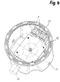
- the housing 3 also has in the region of the housing opening 5 via a mounting flange 17. As can be seen from FIG. 5 there are a total of four nail sleeves 19 on this ceiling side arranged. There are also indentations in the area of these nail sleeves 21 arranged, which increases with increasing distance from expand the nail sleeves.
- the housings are attached to the nail sleeves 3 fastened to the formwork 18 before concreting the ceiling, by striking a nail 29 through a nail sleeve.
- the Indentations 21 obviously facilitate the unhindered Guide the hammer. After the concrete ceiling has hardened, the Formwork 18 removed and the then still protruding nail ends are pinched off.
- connection of the ballast 8 to the electrical lines is obviously relatively simple because of the lines are easily accessible before inserting the reflector. Subsequently the reflector is used and the fluorescent lamp 9 inserted into the lamp holder 7.
- the recessed luminaire with integrated ventilation is continuous Air flow in the direction of the arrow a) through the ventilation pipe 23. Depending on the ventilation conditions, the Air flow can also be reversed, allowing fresh air through the lamp housing is blown into the room.
- Flap 30 To control the amount of air for the supply or exhaust air is one Flap 30 is provided, which manually to a certain open position is set. The flap is after the removal of the reflector easily accessible. But it would also be conceivable to design the end ring for the control of the air volume, that by turning the end ring the ventilation openings can be enlarged or reduced.
Priority Applications (1)
| Application Number | Priority Date | Filing Date | Title |
|---|---|---|---|
| EP00810244A EP1136747A1 (fr) | 2000-03-22 | 2000-03-22 | Eclairage encastrable dans un plafond en béton |
Applications Claiming Priority (1)
| Application Number | Priority Date | Filing Date | Title |
|---|---|---|---|
| EP00810244A EP1136747A1 (fr) | 2000-03-22 | 2000-03-22 | Eclairage encastrable dans un plafond en béton |
Publications (1)
| Publication Number | Publication Date |
|---|---|
| EP1136747A1 true EP1136747A1 (fr) | 2001-09-26 |
Family
ID=8174611
Family Applications (1)
| Application Number | Title | Priority Date | Filing Date |
|---|---|---|---|
| EP00810244A Withdrawn EP1136747A1 (fr) | 2000-03-22 | 2000-03-22 | Eclairage encastrable dans un plafond en béton |
Country Status (1)
| Country | Link |
|---|---|
| EP (1) | EP1136747A1 (fr) |
Cited By (9)
| Publication number | Priority date | Publication date | Assignee | Title |
|---|---|---|---|---|
| WO2007088119A1 (fr) * | 2006-01-31 | 2007-08-09 | Patent-Treuhand-Gesellschaft für elektrische Glühlampen mbH | Appareil d'alimentation et boitier de phare dote d'un appareil d'alimentation |
| FR2936858A1 (fr) * | 2008-10-07 | 2010-04-09 | Luc Philippe Lucien Robichon | Dispositif d'aeration pour systemes lumineux encastres dans un plafond ou un faux plafond. |
| FR2981729A1 (fr) * | 2011-10-24 | 2013-04-26 | Marc Joseph Soudat | Systeme de ventilation thermo-regule d'un luminaire encastre dans un plafond recouvert d'isolant |
| DE202014101536U1 (de) * | 2014-04-01 | 2015-07-06 | Zumtobel Lighting Gmbh | Deckeneinbauleuchte sowie Gehäuse für eine Deckeneinbauleuchte |
| US9574788B2 (en) | 2011-06-02 | 2017-02-21 | Cary Products Co., Inc. | Headliner vent housing |
| CN108561809A (zh) * | 2018-06-05 | 2018-09-21 | 东莞市绿电光电科技有限公司 | 一种照明角度可调的壁灯 |
| USD836048S1 (en) | 2016-10-26 | 2018-12-18 | Cary Products Co., Inc. | Three vane louver |
| US20230167956A1 (en) * | 2021-11-26 | 2023-06-01 | Brilliant Factors Inc. | Recessed concrete luminaire and method of installation thereof |
| CN108561809B (zh) * | 2018-06-05 | 2024-04-23 | 东莞市绿电光电科技有限公司 | 一种照明角度可调的壁灯 |
Citations (6)
| Publication number | Priority date | Publication date | Assignee | Title |
|---|---|---|---|---|
| US3693530A (en) * | 1971-12-29 | 1972-09-26 | Birger Larkfeldt | Ventilated fluorescent tube fixture |
| DE9102903U1 (fr) | 1991-03-11 | 1992-02-06 | Schaetz, Peter, 8021 Baierbrunn, De | |
| US5440471A (en) * | 1994-06-06 | 1995-08-08 | Amp Plus, Inc. | Florescent light fixture assembly |
| US5584575A (en) * | 1995-01-30 | 1996-12-17 | Scientific Nrg. Inc. | Lighting fixture with streamline ballast and method of installation |
| CH687564A5 (de) | 1994-01-25 | 1996-12-31 | Adolf Stoeri | Halogenlampe zum Eingiessen in eine Betondecke und Betondecke mit wenigstens einer derartigen Halogenlampe. |
| US5778625A (en) * | 1995-10-13 | 1998-07-14 | Bega/Us, Inc. | Recessed lighting fixture and method of installing |
-
2000
- 2000-03-22 EP EP00810244A patent/EP1136747A1/fr not_active Withdrawn
Patent Citations (6)
| Publication number | Priority date | Publication date | Assignee | Title |
|---|---|---|---|---|
| US3693530A (en) * | 1971-12-29 | 1972-09-26 | Birger Larkfeldt | Ventilated fluorescent tube fixture |
| DE9102903U1 (fr) | 1991-03-11 | 1992-02-06 | Schaetz, Peter, 8021 Baierbrunn, De | |
| CH687564A5 (de) | 1994-01-25 | 1996-12-31 | Adolf Stoeri | Halogenlampe zum Eingiessen in eine Betondecke und Betondecke mit wenigstens einer derartigen Halogenlampe. |
| US5440471A (en) * | 1994-06-06 | 1995-08-08 | Amp Plus, Inc. | Florescent light fixture assembly |
| US5584575A (en) * | 1995-01-30 | 1996-12-17 | Scientific Nrg. Inc. | Lighting fixture with streamline ballast and method of installation |
| US5778625A (en) * | 1995-10-13 | 1998-07-14 | Bega/Us, Inc. | Recessed lighting fixture and method of installing |
Cited By (10)
| Publication number | Priority date | Publication date | Assignee | Title |
|---|---|---|---|---|
| WO2007088119A1 (fr) * | 2006-01-31 | 2007-08-09 | Patent-Treuhand-Gesellschaft für elektrische Glühlampen mbH | Appareil d'alimentation et boitier de phare dote d'un appareil d'alimentation |
| FR2936858A1 (fr) * | 2008-10-07 | 2010-04-09 | Luc Philippe Lucien Robichon | Dispositif d'aeration pour systemes lumineux encastres dans un plafond ou un faux plafond. |
| US9574788B2 (en) | 2011-06-02 | 2017-02-21 | Cary Products Co., Inc. | Headliner vent housing |
| FR2981729A1 (fr) * | 2011-10-24 | 2013-04-26 | Marc Joseph Soudat | Systeme de ventilation thermo-regule d'un luminaire encastre dans un plafond recouvert d'isolant |
| DE202014101536U1 (de) * | 2014-04-01 | 2015-07-06 | Zumtobel Lighting Gmbh | Deckeneinbauleuchte sowie Gehäuse für eine Deckeneinbauleuchte |
| USD836048S1 (en) | 2016-10-26 | 2018-12-18 | Cary Products Co., Inc. | Three vane louver |
| CN108561809A (zh) * | 2018-06-05 | 2018-09-21 | 东莞市绿电光电科技有限公司 | 一种照明角度可调的壁灯 |
| CN108561809B (zh) * | 2018-06-05 | 2024-04-23 | 东莞市绿电光电科技有限公司 | 一种照明角度可调的壁灯 |
| US20230167956A1 (en) * | 2021-11-26 | 2023-06-01 | Brilliant Factors Inc. | Recessed concrete luminaire and method of installation thereof |
| US11953176B2 (en) * | 2021-11-26 | 2024-04-09 | Brilliant Factors Inc. | Recessed concrete luminaire and method of installation thereof |
Similar Documents
| Publication | Publication Date | Title |
|---|---|---|
| DE2742334A1 (de) | Deckenanordnung sowie beleuchtungseinrichtungen fuer den einbau in derartige deckenanordnungen | |
| EP1936257B1 (fr) | Lampe encastrée dans le sol | |
| EP2696457A2 (fr) | Système de coffrage pour une lampe intégrée dans un mur en béton, lampe intégrée dans un mur en béton et procédé de configuration d'un espace creux dans un mur en béton pour loger une lampe | |
| EP1136747A1 (fr) | Eclairage encastrable dans un plafond en béton | |
| EP2363634B1 (fr) | Lampe à DEL encastrée, notamment plafonnière | |
| EP1637656B1 (fr) | Dispositif avec des diodes électroluminescentes pour le marquage des surfaces | |
| WO1989004436A1 (fr) | Dispositif d'eclairage | |
| CH687564A5 (de) | Halogenlampe zum Eingiessen in eine Betondecke und Betondecke mit wenigstens einer derartigen Halogenlampe. | |
| DE4013457C2 (de) | Anschluß- und Aufhängevorrichtung für Deckenleuchten | |
| DE2515131A1 (de) | Installationsdose mit mindestens einem loesbaren anschlussteil | |
| DE3836611A1 (de) | Decken-einbauleuchte fuer eine paneeldecke | |
| EP2365151B1 (fr) | Lampe | |
| AT17301U1 (de) | Anpassbarer Träger für in Unterwassernischen installierte Leuchten | |
| EP0166234A2 (fr) | Boîte de jonction pour installation de distribution d'eau | |
| DE202004011168U1 (de) | Leuchte, insbesondere Pflastersteinleuchte | |
| CH711488B1 (de) | Einbaubüchsendeckel zum Verschliessen einer Öffnung in einer Einbaubüchse. | |
| EP3505707A1 (fr) | Appareillage ainsi que procédé de formation d'une zone fonctionnelle dans un composant d'un matériau de construction coulable et durcissable | |
| DE2623505A1 (de) | Gartenlampe | |
| DE19652110A1 (de) | Lichtpaneel | |
| DE19547267C2 (de) | Druckwasser- und gasdichte Strahlerleuchte für universelle Anwendung | |
| CH719420A2 (de) | Integrale Beleuchtungseinheit. | |
| WO2010063042A1 (fr) | Dispositif de fixation d'un éclairage à une surface de bâtiment | |
| DE10118783B4 (de) | Montagesystem für ein Leuchtenbauteil sowie Leuchte mit einem solchen Montagesystem | |
| CH663814A5 (de) | Bauelementensatz fuer die unterputzmontage von armaturen. | |
| DE29812643U1 (de) | Leuchtengehäuse für den Einbau in ein Betonbauteil, insbesondere in eine Betondecke |
Legal Events
| Date | Code | Title | Description |
|---|---|---|---|
| PUAI | Public reference made under article 153(3) epc to a published international application that has entered the european phase |
Free format text: ORIGINAL CODE: 0009012 |
|
| AK | Designated contracting states |
Kind code of ref document: A1 Designated state(s): AT CH DE FR IT LI Kind code of ref document: A1 Designated state(s): AT BE CH CY DE DK ES FI FR GB GR IE IT LI LU MC NL PT SE |
|
| AX | Request for extension of the european patent |
Free format text: AL;LT;LV;MK;RO;SI |
|
| 17P | Request for examination filed |
Effective date: 20011008 |
|
| AKX | Designation fees paid |
Free format text: AT CH DE FR IT LI |
|
| 17Q | First examination report despatched |
Effective date: 20020722 |
|
| STAA | Information on the status of an ep patent application or granted ep patent |
Free format text: STATUS: THE APPLICATION IS DEEMED TO BE WITHDRAWN |
|
| 18D | Application deemed to be withdrawn |
Effective date: 20031230 |