EP1136747A1 - Recessed light fixture for a concrete ceiling - Google Patents
Recessed light fixture for a concrete ceiling Download PDFInfo
- Publication number
- EP1136747A1 EP1136747A1 EP00810244A EP00810244A EP1136747A1 EP 1136747 A1 EP1136747 A1 EP 1136747A1 EP 00810244 A EP00810244 A EP 00810244A EP 00810244 A EP00810244 A EP 00810244A EP 1136747 A1 EP1136747 A1 EP 1136747A1
- Authority
- EP
- European Patent Office
- Prior art keywords
- housing
- reflector
- opening
- lamp
- recessed
- Prior art date
- Legal status (The legal status is an assumption and is not a legal conclusion. Google has not performed a legal analysis and makes no representation as to the accuracy of the status listed.)
- Withdrawn
Links
Images


Classifications
-
- F—MECHANICAL ENGINEERING; LIGHTING; HEATING; WEAPONS; BLASTING
- F21—LIGHTING
- F21V—FUNCTIONAL FEATURES OR DETAILS OF LIGHTING DEVICES OR SYSTEMS THEREOF; STRUCTURAL COMBINATIONS OF LIGHTING DEVICES WITH OTHER ARTICLES, NOT OTHERWISE PROVIDED FOR
- F21V29/00—Protecting lighting devices from thermal damage; Cooling or heating arrangements specially adapted for lighting devices or systems
- F21V29/50—Cooling arrangements
- F21V29/70—Cooling arrangements characterised by passive heat-dissipating elements, e.g. heat-sinks
- F21V29/83—Cooling arrangements characterised by passive heat-dissipating elements, e.g. heat-sinks the elements having apertures, ducts or channels, e.g. heat radiation holes
-
- F—MECHANICAL ENGINEERING; LIGHTING; HEATING; WEAPONS; BLASTING
- F21—LIGHTING
- F21V—FUNCTIONAL FEATURES OR DETAILS OF LIGHTING DEVICES OR SYSTEMS THEREOF; STRUCTURAL COMBINATIONS OF LIGHTING DEVICES WITH OTHER ARTICLES, NOT OTHERWISE PROVIDED FOR
- F21V29/00—Protecting lighting devices from thermal damage; Cooling or heating arrangements specially adapted for lighting devices or systems
- F21V29/50—Cooling arrangements
- F21V29/60—Cooling arrangements characterised by the use of a forced flow of gas, e.g. air
-
- F—MECHANICAL ENGINEERING; LIGHTING; HEATING; WEAPONS; BLASTING
- F21—LIGHTING
- F21S—NON-PORTABLE LIGHTING DEVICES; SYSTEMS THEREOF; VEHICLE LIGHTING DEVICES SPECIALLY ADAPTED FOR VEHICLE EXTERIORS
- F21S8/00—Lighting devices intended for fixed installation
- F21S8/02—Lighting devices intended for fixed installation of recess-mounted type, e.g. downlighters
-
- F—MECHANICAL ENGINEERING; LIGHTING; HEATING; WEAPONS; BLASTING
- F21—LIGHTING
- F21V—FUNCTIONAL FEATURES OR DETAILS OF LIGHTING DEVICES OR SYSTEMS THEREOF; STRUCTURAL COMBINATIONS OF LIGHTING DEVICES WITH OTHER ARTICLES, NOT OTHERWISE PROVIDED FOR
- F21V15/00—Protecting lighting devices from damage
- F21V15/01—Housings, e.g. material or assembling of housing parts
-
- F—MECHANICAL ENGINEERING; LIGHTING; HEATING; WEAPONS; BLASTING
- F21—LIGHTING
- F21V—FUNCTIONAL FEATURES OR DETAILS OF LIGHTING DEVICES OR SYSTEMS THEREOF; STRUCTURAL COMBINATIONS OF LIGHTING DEVICES WITH OTHER ARTICLES, NOT OTHERWISE PROVIDED FOR
- F21V19/00—Fastening of light sources or lamp holders
- F21V19/0075—Fastening of light sources or lamp holders of tubular light sources, e.g. ring-shaped fluorescent light sources
- F21V19/0095—Fastening of light sources or lamp holders of tubular light sources, e.g. ring-shaped fluorescent light sources of U-shaped tubular light sources, e.g. compact fluorescent tubes
-
- F—MECHANICAL ENGINEERING; LIGHTING; HEATING; WEAPONS; BLASTING
- F21—LIGHTING
- F21V—FUNCTIONAL FEATURES OR DETAILS OF LIGHTING DEVICES OR SYSTEMS THEREOF; STRUCTURAL COMBINATIONS OF LIGHTING DEVICES WITH OTHER ARTICLES, NOT OTHERWISE PROVIDED FOR
- F21V21/00—Supporting, suspending, or attaching arrangements for lighting devices; Hand grips
- F21V21/02—Wall, ceiling, or floor bases; Fixing pendants or arms to the bases
- F21V21/04—Recessed bases
-
- F—MECHANICAL ENGINEERING; LIGHTING; HEATING; WEAPONS; BLASTING
- F21—LIGHTING
- F21V—FUNCTIONAL FEATURES OR DETAILS OF LIGHTING DEVICES OR SYSTEMS THEREOF; STRUCTURAL COMBINATIONS OF LIGHTING DEVICES WITH OTHER ARTICLES, NOT OTHERWISE PROVIDED FOR
- F21V23/00—Arrangement of electric circuit elements in or on lighting devices
- F21V23/02—Arrangement of electric circuit elements in or on lighting devices the elements being transformers, impedances or power supply units, e.g. a transformer with a rectifier
-
- F—MECHANICAL ENGINEERING; LIGHTING; HEATING; WEAPONS; BLASTING
- F21—LIGHTING
- F21Y—INDEXING SCHEME ASSOCIATED WITH SUBCLASSES F21K, F21L, F21S and F21V, RELATING TO THE FORM OR THE KIND OF THE LIGHT SOURCES OR OF THE COLOUR OF THE LIGHT EMITTED
- F21Y2103/00—Elongate light sources, e.g. fluorescent tubes
- F21Y2103/30—Elongate light sources, e.g. fluorescent tubes curved
- F21Y2103/37—U-shaped
Definitions
- the invention relates to a recessed light for a concrete ceiling.
- Such lights already require the manufacture of the concrete ceiling
- Appropriate measures so that the lamp is complete is integrated into the concrete ceiling, including the electrical Line pipes must be concreted in beforehand.
- Recessed luminaires of the same type are already available for Various types of lamps are known, but in particular for low-voltage halogen lamps.
- DE-U-91 02 903.1 describes a concrete installation pot, its open end by means of a cover plate can be closed with a circular opening.
- CH-A-687 564 a recessed light for halogen lamps is described in which the transformer and the lamp holder can be detached in one concreted housing are held and by the room side Lamp opening are removable from the housing.
- Ballasts have so far not been a satisfactory installation solution known.
- the lights are largely in hollow ceilings of rooms that are ventilated via the hollow ceiling.
- a common installation option for direct installation in Concrete ceilings consist of being relatively voluminous and always to pour in two parts of the existing, closed housing. This creates a cavity in the concrete ceiling that is practically comparable to a hollow ceiling. In this case an opening is then cut depending on the configuration of the luminaire, to install the lamp with the ballast.
- This method of installation is very complex and labor-intensive the actual attachment of the lamp in the housing is unsatisfactory is solved.
- the relatively large housing claims already a lot of space for storage and they also weaken the Concrete floor.
- This task is solved with a recessed lamp, which has the features in the claim 1 has.
- the pot-like housing is directly part of the Luminaire and not only serves to create a cavity in the Concrete floor.
- the entire built-in module can be attached to the connection means consisting of lamp holder, ballast and reflector with simple means and without improvisation from the side of the housing opening be releasably attached here.
- the preferred side Lamp opening in the reflector allows a horizontal lamp position and therefore a particularly small installation depth.
- the Installation module can also be used for storage purposes when not installed be attached in the housing, the latter the sensitive Protects parts of the lamp from external influences. Through the compact design, the total height of the lamp can be from 12 to 14 cm can be reduced, which means installation in concrete ceilings of approx. 20 cm thickness allowed.
- connection means are preferably in one piece with the housing trained stops, for example in the form of at least three stud bolts arranged on the housing base.
- the housing can be used together with the connection means made of plastic material, for example from a glass fiber reinforced plastic material be produced particularly easily and inexpensively.
- the lamp holder can be arranged on a holding plate, which is screwed to the connection means, the reflector in turn with a screw connection on the holding plate is attached.
- the holding plate can be in the area of Lamp opening have a bend on the lamp holder is fixed.
- the reflector is advantageously attached via a threaded bolt attached to the holding plate, which penetrates an opening in the center of the reflector, wherein the reflector is held by a nut. To remove of the reflector or the entire built-in module only has to the fluorescent lamp is unplugged from the lamp holder, whereupon the individual connections can be released.
- the ballast is also preferably on the bottom of the housing facing side of the holding plate attached to this. Conceivable would also be an attachment to the connection means.
- the annular gap between the outer edge of the housing opening and the The outer edge of the reflector is preferably provided with ventilation openings provided end ring covered by the Outer edge of the reflector is pressed against the housing.
- the end ring is the only component of the Recessed light that is visible from the outside. It serves among other things also covering the transition between the room side of the Concrete ceiling and the housing, which for technical reasons is not can always be designed to exact dimensions.
- the graduation ring can be made of different materials and it can be different Show colors.
- the preferred ventilation openings serve the ventilation of the through the reflector delimited interior of the housing. Because the finishing ring through pressed the reflector against the housing or against the concrete ceiling no additional connecting means are required. There is also a limited eccentric shift of the end ring possible.
- the housing has a mounting flange at the housing opening on which it is on the formwork of the concrete ceiling can be fixed, with at least two nail sleeves on the ceiling side are arranged on the mounting flange and the side wall one indentation of the housing in the area of the nail sleeves having.
- the housing can also have at least one Ventilation pipe connected, which is also laid beforehand and through which an air flow can be maintained through the housing is.
- the ventilation pipe preferably has a slightly larger cross section than the conduit. It can be with a fan or with an if necessary existing ventilation system in the building. The ventilation in the case also contributes to the dimensions can be kept very small without heat build-up can form.
- An adjustable flap can be provided for exhaust air is easily accessible after removing the reflector.
- a recessed light 1 for installation in a concrete ceiling 2 essentially from a housing 3 and from a built-in module with a lamp holder 7, with a ballast 8 and with a reflector 10.
- the housing 3 is part of the recessed light, is however, concreted in before inserting the built-in module.
- the housing base 4 Stud 6 integrally connected to the housing.
- the stud bolts are directed against the housing opening 5 and for an increase the bending stiffness with reinforcing wings.
- the Stud bolts serve as connection means for fastening the Built-in module.
- a holding plate 12 the floor plan of Figure 3 can be seen by means of screws 25 on the end faces the stud bolt 6 screwed.
- the holding plate is on one Side with a bend 13 on which a lamp holder 7 is attached. In the present case it is about a twin socket for two fluorescent lamps 9, the lamp position being horizontal.
- ballast 8 On the side of the holding plate 12 facing the housing base 4 is the ballast 8 also preferably by means of screws attached.
- the ballast is within the four Stud 6, but it could also be offset laterally behind the Reflector 10 may be arranged.
- a threaded bolt 14 is arranged in the center. This penetrates an opening in the center of the reflector 10, the latter screwed against the holding plate by means of a nut 15 can be.
- the reflector has a side lamp opening 11, which is arranged such that the lamp holder 7 is easily accessible.
- the reflector 10 also has in the area of the housing opening 5 over an angled outer edge 27. This overlaps one End ring 16, which has elongated ventilation openings 24 is provided. When the reflector is screwed tight, the end ring 16 with its angled outer edge 26 against the housing 3 or pressed against the concrete ceiling 2.
- the housing wall 20 a light suit at an angle ⁇ .
- the side wall 20 are also the side openings 28 for the line pipes 22 or arranged for a ventilation pipe 23.
- the side openings can be designed in such a way that they can be used on different Pages can be broken out.
- the housing 3 also has in the region of the housing opening 5 via a mounting flange 17. As can be seen from FIG. 5 there are a total of four nail sleeves 19 on this ceiling side arranged. There are also indentations in the area of these nail sleeves 21 arranged, which increases with increasing distance from expand the nail sleeves.
- the housings are attached to the nail sleeves 3 fastened to the formwork 18 before concreting the ceiling, by striking a nail 29 through a nail sleeve.
- the Indentations 21 obviously facilitate the unhindered Guide the hammer. After the concrete ceiling has hardened, the Formwork 18 removed and the then still protruding nail ends are pinched off.
- connection of the ballast 8 to the electrical lines is obviously relatively simple because of the lines are easily accessible before inserting the reflector. Subsequently the reflector is used and the fluorescent lamp 9 inserted into the lamp holder 7.
- the recessed luminaire with integrated ventilation is continuous Air flow in the direction of the arrow a) through the ventilation pipe 23. Depending on the ventilation conditions, the Air flow can also be reversed, allowing fresh air through the lamp housing is blown into the room.
- Flap 30 To control the amount of air for the supply or exhaust air is one Flap 30 is provided, which manually to a certain open position is set. The flap is after the removal of the reflector easily accessible. But it would also be conceivable to design the end ring for the control of the air volume, that by turning the end ring the ventilation openings can be enlarged or reduced.
Abstract
Description
Die Erfindung betrifft eine Einbauleuchte für eine Betondecke. Derartige Leuchten erfordern bereits bei der Herstellung der Betondecke entsprechende Massnahmen, so dass die Leuchte vollständig in die Betondecke integriert ist, wobei auch die elektrischen Leitungsrohre vorgängig einbetoniert werden.The invention relates to a recessed light for a concrete ceiling. Such lights already require the manufacture of the concrete ceiling Appropriate measures so that the lamp is complete is integrated into the concrete ceiling, including the electrical Line pipes must be concreted in beforehand.
Gattungsmässig vergleichbare Einbauleuchten sind bereits für verschiedene Lampentypen bekannt, insbesondere aber für Halogen-Niedervoltlampen. So beschreibt die DE-U-91 02 903.1 einen Betoneinbautopf, dessen offenes Ende mittels einer Abdeckplatte mit kreisrunder Öffnung verschliessbar ist. In der CH-A-687 564 ist eine Einbauleuchte für Halogenlampen beschrieben, bei welcher der Transformator und die Lampenhalterung lösbar in einem einbetonierten Gehäuse gehalten sind und durch die raumseitige Lampenöffnung aus dem Gehäuse herausnehmbar sind.Recessed luminaires of the same type are already available for Various types of lamps are known, but in particular for low-voltage halogen lamps. DE-U-91 02 903.1 describes a concrete installation pot, its open end by means of a cover plate can be closed with a circular opening. In CH-A-687 564 a recessed light for halogen lamps is described in which the transformer and the lamp holder can be detached in one concreted housing are held and by the room side Lamp opening are removable from the housing.
Für Leuchtstofflampen mit den zu deren Betrieb erforderlichen Vorschaltgeräten waren bisher keine befriedigenden Einbaulösungen bekannt. Die Leuchten werden zum grossen Teil in Hohldecken von Räumen eingebaut, die über die Hohldecke belüftet werden. Eine verbreitete Einbaumöglichkeit für den direkten Einbau in Betondecken besteht darin, ein relativ voluminöses und stets aus zwei Teilen bestehendes, geschlossenes Gehäuse einzubetonieren. Dadurch wird in der Betondecke ein Hohlraum geschaffen, der praktisch mit einer Hohldecke vergleichbar ist. In dieses Gehäuse wird dann je nach Konfiguration der Leuchte eine Öffnung geschnitten, um die Leuchte mit dem Vorschaltgerät einzubauen. Diese Einbauweise ist sehr aufwendig und arbeitsintensiv, wobei die eigentliche Befestigung der Leuchte im Gehäuse nicht zufriedenstellend gelöst ist. Die relativ grossen Gehäuse beanspruchen schon für die Lagerung viel Platz und sie schwächen zudem die Betondecke.For fluorescent lamps with the necessary for their operation Ballasts have so far not been a satisfactory installation solution known. The lights are largely in hollow ceilings of rooms that are ventilated via the hollow ceiling. A common installation option for direct installation in Concrete ceilings consist of being relatively voluminous and always to pour in two parts of the existing, closed housing. This creates a cavity in the concrete ceiling that is practically comparable to a hollow ceiling. In this case an opening is then cut depending on the configuration of the luminaire, to install the lamp with the ballast. This method of installation is very complex and labor-intensive the actual attachment of the lamp in the housing is unsatisfactory is solved. The relatively large housing claims already a lot of space for storage and they also weaken the Concrete floor.
Es ist daher eine Aufgabe der Erfindung, eine Einbauleuchte für eine Betondecke zu schaffen, welche einfach und mit geringer Einbautiefe in die Betondecke einbaubar ist, wobei auch nachträglich für Wartungsarbeiten das Vorschaltgerät bzw. die Lampenfassungen jederzeit leicht zugänglich sind. Diese Aufgabe wird mit einer Einbauleuchte gelöst, welche die Merkmale im Anspruch 1 aufweist.It is therefore an object of the invention to provide a downlight for to create a concrete ceiling that is simple and with little Installation depth can be installed in the concrete ceiling, even afterwards the ballast or lamp holders for maintenance work are easily accessible at all times. This task is solved with a recessed lamp, which has the features in the claim 1 has.
Das topfartige Gehäuse ist dabei unmittelbar Bestandteil der Leuchte und dient nicht nur der Schaffung eines Hohlraums in der Betondecke. An den Anschlussmitteln kann das gesamte Einbaumodul bestehend aus Lampenfassung, Vorschaltgerät und Reflektor mit einfachen Mitteln und ohne Improvisation von der Seite der Gehäuseöffnung her lösbar befestigt werden. Die vorzugsweise seitliche Lampenöffnung im Reflektor erlaubt eine horizontale Lampenstellung und damit eine besonders geringe Einbautiefe. Das Einbaumodul kann auch im nichtmontierten Zustand für Lagerzwecke im Gehäuse befestigt werden, wobei letzteres die empfindlichen Teile der Leuchte vor äusseren Einwirkungen schützt. Durch die kompakte Bauweise kann die Gesamthöhe der Leuchte auf 12 bis 14 cm reduziert werden, was einen Einbau in Betondecken von ca. 20 cm Dicke erlaubt.The pot-like housing is directly part of the Luminaire and not only serves to create a cavity in the Concrete floor. The entire built-in module can be attached to the connection means consisting of lamp holder, ballast and reflector with simple means and without improvisation from the side of the housing opening be releasably attached here. The preferred side Lamp opening in the reflector allows a horizontal lamp position and therefore a particularly small installation depth. The Installation module can also be used for storage purposes when not installed be attached in the housing, the latter the sensitive Protects parts of the lamp from external influences. Through the compact design, the total height of the lamp can be from 12 to 14 cm can be reduced, which means installation in concrete ceilings of approx. 20 cm thickness allowed.
Die Anschlussmittel sind vorzugsweise einstückig mit dem Gehäuse ausgebildete Anschläge, beispielsweise in der Form von wenigstens drei am Gehäuseboden angeordneten Stehbolzen. Das Gehäuse kann dabei zusammen mit den Anschlussmitteln aus Kunststoffmaterial, beispielsweise aus einem glasfaserverstärkten Kunststoffmaterial besonders einfach und kostengünstig hergestellt werden. The connection means are preferably in one piece with the housing trained stops, for example in the form of at least three stud bolts arranged on the housing base. The housing can be used together with the connection means made of plastic material, for example from a glass fiber reinforced plastic material be produced particularly easily and inexpensively.
In bestimmten Anwendungsfällen wäre aber auch eine Ausführung in Metall denkbar.In certain applications, however, an execution would also be in Metal conceivable.
Die Lampenfassung kann an einer Halteplatte angeordnet sein, welche an die Anschlussmittel angeschraubt ist, wobei der Reflektor seinerseits mit einer Schraubverbindung an der Halteplatte befestigt ist. Die Halteplatte kann dabei im Bereich der Lampenöffnung eine Abwinklung aufweisen, an der die Lampenfassung fixiert ist. Die Befestigung des Reflektors erfolgt vorteilhaft über einen an der Halteplatte befestigten Gewindebolzen, der eine Öffnung im Zentrum des Reflektors durchdringt, wobei der Reflektor mittels einer Mutter gehalten ist. Zum Entfernen des Reflektors bzw. des ganzen Einbaumoduls muss somit nur die Leuchtstofflampe aus der Lampenfassung ausgesteckt werden, worauf die einzelnen Verbindungen gelöst werden können.The lamp holder can be arranged on a holding plate, which is screwed to the connection means, the reflector in turn with a screw connection on the holding plate is attached. The holding plate can be in the area of Lamp opening have a bend on the lamp holder is fixed. The reflector is advantageously attached via a threaded bolt attached to the holding plate, which penetrates an opening in the center of the reflector, wherein the reflector is held by a nut. To remove of the reflector or the entire built-in module only has to the fluorescent lamp is unplugged from the lamp holder, whereupon the individual connections can be released.
Auch das Vorschaltgerät ist vorzugsweise auf der dem Gehäuseboden zugewandten Seite der Halteplatte an dieser befestigt. Denkbar wäre aber auch eine Befestigung an den Anschlussmitteln.The ballast is also preferably on the bottom of the housing facing side of the holding plate attached to this. Conceivable would also be an attachment to the connection means.
Der Ringspalt zwischen dem Aussenrand der Gehäuseöffnung und dem Aussenrand des Reflektors ist durch einen vorzugsweise mit Lüftungsöffnungen versehenen Abschlussring abgedeckt, der durch den Aussenrand des Reflektors gegen das Gehäuse gepresst wird. Der Abschlussring ist neben dem Reflektor das einzige Bauteil der Einbauleuchte, das von aussen sichtbar ist. Er dient unter anderem auch der Abdeckung des Übergangs zwischen der Raumseite der Betondecke und dem Gehäuse, der aus technischen Gründen nicht immer exakt masshaltig gestaltet werden kann. Der Abschlussring kann aus verschiedenen Werkstoffen bestehen und er kann verschiedene Farben aufweisen. Die vorzugsweise vorgesehenen Lüftungsöffnungen dienen der Ventilation des durch den Reflektor abgegrenzten Innenraums des Gehäuses. Da der Abschlussring durch den Reflektor gegen das Gehäuse bzw. gegen die Betondecke gepresst wird, sind keinerlei zusätzliche Verbindungsmittel erforderlich. Ausserdem ist eine begrenzte exzentrische Verschiebung des Abschlussrings möglich.The annular gap between the outer edge of the housing opening and the The outer edge of the reflector is preferably provided with ventilation openings provided end ring covered by the Outer edge of the reflector is pressed against the housing. The In addition to the reflector, the end ring is the only component of the Recessed light that is visible from the outside. It serves among other things also covering the transition between the room side of the Concrete ceiling and the housing, which for technical reasons is not can always be designed to exact dimensions. The graduation ring can be made of different materials and it can be different Show colors. The preferred ventilation openings serve the ventilation of the through the reflector delimited interior of the housing. Because the finishing ring through pressed the reflector against the housing or against the concrete ceiling no additional connecting means are required. There is also a limited eccentric shift of the end ring possible.
Weitere Vorteile bezüglich der Montage der Einbauleuchte können erzielt werden, wenn das Gehäuse an der Gehäuseöffnung einen Befestigungsflansch aufweist, an dem es an der Schalung der Betondecke fixierbar ist, wobei deckenseitig wenigstens zwei Nagelhülsen am Befestigungsflansch angeordnet sind und wobei die Seitenwand des Gehäuses im Bereich der Nagelhülsen je eine Einbuchtung aufweist. Bei der Montage wird das leere Gehäuse mit dem Befestigungsflansch auf die Schalung aufgelegt und durch Einschlagen von Nägeln durch die Nagelbüchsen befestigt. Die Nagelbüchsen stellen dabei sicher, dass die Nägel gerade und geführt in die Schalung eindringen. Die Einbuchtung im Bereich der Nagelbüchsen schafft den nötigen Freiraum, um den Hammer zum Einschlagen der Nägel ungehindert zu führen.Other advantages regarding the installation of the recessed luminaire can can be achieved if the housing has a mounting flange at the housing opening on which it is on the formwork of the concrete ceiling can be fixed, with at least two nail sleeves on the ceiling side are arranged on the mounting flange and the side wall one indentation of the housing in the area of the nail sleeves having. When assembling the empty housing with the Fixing flange placed on the formwork and by hammering attached by nails through the nail cans. The nail tins make sure that the nails are straight and guided penetrate the formwork. The indentation in the area of the nail tins creates the necessary space to hammer the hammer in to guide the nails freely.
Herstellungstechnisch ist es besonders vorteilhaft, wenn sich die Seitenwand des Gehäuses von der Gehäuseöffnung gegen den Gehäuseboden konisch verjüngt. Ein derartiges Formteil lässt sich im Spritzgussverfahren besonders einfach entformen.In terms of production technology, it is particularly advantageous if the side wall of the case from the case opening against the case bottom tapered. Such a molded part can be Demoulding is particularly easy in the injection molding process.
Beim Herstellen der Betondecke müssen ersichtlicherweise auch die Leitungsrohre für die elektrische Leitungsführung vor dem Betonieren verlegt und zu den einzelnen Gehäusen geführt werden. Zusätzlich kann das Gehäuse aber auch noch mit wenigstens einem Lüftungsrohr verbunden sein, das ebenfalls vorgängig verlegt wird und über das durch das Gehäuse eine Luftströmung aufrechterhaltbar ist. So lässt sich besonders einfach auch ein Raum ventilieren, der nicht mit einer Hohldecke, sondern nur mit einer einfachen Betondecke versehen ist. Das Lüftungsrohr hat vorzugsweise einen etwas grösseren Querschnitt als das Leitungsrohr. Es kann mit einem Ventilator oder mit einem gegebenenfalls vorhandenen Lüftungssystem im Gebäude verbunden sein. Die Belüftung im Gehäuse trägt auch noch dazu bei, dass die Dimensionen sehr klein gehalten werden können, ohne dass sich ein Wärmestau bilden kann. Für die Einstellung der Luftmenge für die Zu- oder Abluft kann eine einstellbare Klappe vorgesehen sein, welche nach dem Ausbau des Reflektors gut zugänglich ist.Obviously, when manufacturing the concrete ceiling also the conduits for the electrical wiring in front of the Concreting laid and led to the individual housings. In addition, the housing can also have at least one Ventilation pipe connected, which is also laid beforehand and through which an air flow can be maintained through the housing is. This makes it particularly easy to create a room ventilate, not with a hollow ceiling, but only with one simple concrete ceiling. The ventilation pipe preferably has a slightly larger cross section than the conduit. It can be with a fan or with an if necessary existing ventilation system in the building. The ventilation in the case also contributes to the dimensions can be kept very small without heat build-up can form. For setting the air volume for the intake or An adjustable flap can be provided for exhaust air is easily accessible after removing the reflector.
Weitere Vorteile und Einzelmerkmale der Erfindung ergeben sich aus dem nachstehend beschriebenen Ausführungsbeispiel und aus den Zeichnungen. Es zeigen:
- Figur 1
- einen Querschnitt durch eine Betondecke mit einer erfindungsgemässen Einbauleuchte,
- Figur 2
- einen Querschnitt durch die Ebene I-I an der Einbauleuchte gemäss Figur 1,
Figur 3- eine Ansicht aus Pfeilrichtung A der Einbauleuchte gemäss Figur 2,
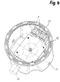
Figur 4- eine perspektivische Darstellung der Einbauleuchte gemäss
Figur 3, und - Figur 5
- eine perspektivische Darstellung eines Gehäuses beim Befestigen auf der Schalung.
- Figure 1
- 3 shows a cross section through a concrete ceiling with a recessed luminaire according to the invention,
- Figure 2
- 3 shows a cross section through plane II on the built-in lamp according to FIG. 1,
- Figure 3
- 2 shows a view from the direction of arrow A of the recessed light according to FIG. 2,
- Figure 4
- a perspective view of the recessed light according to Figure 3, and
- Figure 5
- a perspective view of a housing when attaching to the formwork.
Wie insbesondere in Figur 1 dargestellt, besteht eine Einbauleuchte
1 für den Einbau in eine Betondecke 2 im Wesentlichen
aus einem Gehäuse 3 und aus einem Einbaumodul mit einer Lampenfassung
7, mit einem Vorschaltgerät 8 und mit einem Reflektor
10. Das Gehäuse 3 ist zwar Bestandteil der Einbauleuchte, wird
jedoch vor dem Einsetzen des Einbaumoduls einbetoniert.As shown in particular in Figure 1, there is a recessed light
1 for installation in a concrete ceiling 2 essentially
from a
Am Gehäuseboden 4 sind in einer rechteckigen Anordnung vier
Stehbolzen 6 einstückig mit dem Gehäuse verbunden. Die Stehbolzen
sind gegen die Gehäuseöffnung 5 gerichtet und für eine Erhöhung
der Biegesteifigkeit mit Verstärkungsflügeln versehen. Die
Stehbolzen dienen als Anschlussmittel für die Befestigung des
Einbaumoduls.There are four in a rectangular arrangement on the
Zu diesem Zweck wird eine Halteplatte 12, deren Grundriss aus
Figur 3 ersichtlich ist, mittels Schrauben 25 auf die Stirnseiten
der Stehbolzen 6 geschraubt. Die Halteplatte ist auf einer
Seite mit einer Abwinklung 13 versehen, an welcher eine Lampenfassung
7 befestigt ist. Im vorliegenden Fall handelt es sich um
eine Zwillingsfassung für die Aufnahme von zwei Leuchtstofflampen
9, wobei die Lampenstellung horizontal verläuft.For this purpose, a holding
Auf der dem Gehäuseboden 4 zugewandten Seite der Halteplatte 12
ist das Vorschaltgerät 8 vorzugsweise ebenfalls mittels Schrauben
befestigt. Das Vorschaltgerät liegt dabei innerhalb der vier
Stehbolzen 6, es könnte aber auch seitlich versetzt hinter dem
Reflektor 10 angeordnet sein.On the side of the holding
Auf der der Gehäuseöffnung 5 zugewandten Seite der Halteplatte
12 ist im Zentrum ein Gewindebolzen 14 angeordnet. Dieser durchdringt
eine Öffnung im Zentrum des Reflektors 10, wobei letzterer
mittels einer Mutter 15 gegen die Halteplatte geschraubt
werden kann. Der Reflektor verfügt über eine seitliche Lampenöffnung
11, welche derart angeordnet ist, dass die Lampenfassung
7 gut zugänglich ist. On the side of the holding plate facing the housing opening 5
12, a threaded
Der Reflektor 10 verfügt ausserdem im Bereich der Gehäuseöffnung
5 über einen abgewinkelten Aussenrand 27. Dieser übergreift einen
Abschlussring 16, der mit länglichen Lüftungsöffnungen 24
versehen ist. Bei festgeschraubtem Reflektor wird der Abschlussring
16 mit seiner abgewinkelten Aussenkante 26 gegen das Gehäuse
3 bzw. gegen die Betondecke 2 gepresst.The
Wie insbesondere aus Figur 2 ersichtlich ist, hat die Gehäusewand
20 einen leichten Anzug unter einem Winkel α. In der Seitenwand
20 sind auch die Seitenöffnungen 28 für die Leitungsrohre
22 bzw. für ein Lüftungsrohr 23 angeordnet. Die Seitenöffnungen
können so ausgestaltet sein, dass sie wahlweise auf verschiedenen
Seiten ausgebrochen werden können.As can be seen in particular from Figure 2, the housing wall
20 a light suit at an angle α. In the
Im Bereich der Gehäuseöffnung 5 verfügt das Gehäuse 3 ausserdem
über einen Befestigungsflansch 17. Wie aus Figur 5 ersichtlich
ist, sind an diesem deckenseitig insgesamt vier Nagelhülsen 19
angeordnet. Im Bereich dieser Nagelhülsen sind ausserdem Einbuchtungen
21 angeordnet, die sich mit zunehmender Distanz von
den Nagelhülsen erweitern. An den Nagelhülsen werden die Gehäuse
3 vor dem Betonieren der Decke auf der Schalung 18 befestigt,
indem je ein Nagel 29 durch eine Nagelhülse geschlagen wird. Die
Einbuchtungen 21 erleichtern ersichtlicherweise die ungehinderte
Führung des Hammers. Nach dem Aushärten der Betondecke wird die
Schalung 18 entfernt und die dann noch herausragenden Nagelenden
werden abgeklemmt.The
Das Anschliessen des Vorschaltgerätes 8 an die elektrischen Leitungen
ist ersichtlicherweise relativ einfach, weil die Leitungen
vor dem Einsetzen des Reflektors gut zugänglich sind. Anschliessend
wird der Reflektor eingesetzt und die Leuchtstofflampe
9 in die Lampenfassung 7 eingesteckt. Beim Betrieb
der Einbauleuchte mit integrierter Belüftung erfolgt eine kontinuierliche
Luftströmung in Pfeilrichtung a) durch das Lüftungsrohr
23. Je nach den lüftungstechnischen Gegebenheiten kann die
Luftströmung auch reversiert werden, so dass Frischluft durch
das Lampengehäuse in den Raum geblasen wird.The connection of the
Zur Steuerung der Luftmenge für die Zu- oder Abluft ist eine
Klappe 30 vorgesehen, welche manuell auf eine bestimmte Öffnungsstellung
eingestellt wird. Die Klappe ist nach der Entfernung
des Reflektors gut zugänglich. Es wäre aber auch denkbar,
den Abschlussring für die Steuerung der Luftmenge so auszubilden,
dass durch Drehen am Abschlussring die Lüftungsöffnungen
vergrössert oder verkleinert werden können.To control the amount of air for the supply or exhaust air is one
Claims (12)
Priority Applications (1)
| Application Number | Priority Date | Filing Date | Title |
|---|---|---|---|
| EP00810244A EP1136747A1 (en) | 2000-03-22 | 2000-03-22 | Recessed light fixture for a concrete ceiling |
Applications Claiming Priority (1)
| Application Number | Priority Date | Filing Date | Title |
|---|---|---|---|
| EP00810244A EP1136747A1 (en) | 2000-03-22 | 2000-03-22 | Recessed light fixture for a concrete ceiling |
Publications (1)
| Publication Number | Publication Date |
|---|---|
| EP1136747A1 true EP1136747A1 (en) | 2001-09-26 |
Family
ID=8174611
Family Applications (1)
| Application Number | Title | Priority Date | Filing Date |
|---|---|---|---|
| EP00810244A Withdrawn EP1136747A1 (en) | 2000-03-22 | 2000-03-22 | Recessed light fixture for a concrete ceiling |
Country Status (1)
| Country | Link |
|---|---|
| EP (1) | EP1136747A1 (en) |
Cited By (9)
| Publication number | Priority date | Publication date | Assignee | Title |
|---|---|---|---|---|
| WO2007088119A1 (en) * | 2006-01-31 | 2007-08-09 | Patent-Treuhand-Gesellschaft für elektrische Glühlampen mbH | Operating device and headlight housing with an operating device |
| FR2936858A1 (en) * | 2008-10-07 | 2010-04-09 | Luc Philippe Lucien Robichon | AERATION DEVICE FOR LIGHTING SYSTEMS IN A CEILING OR A FALSE CEILING. |
| FR2981729A1 (en) * | 2011-10-24 | 2013-04-26 | Marc Joseph Soudat | Thermo-regulated ventilation system for lighting spot embedded in e.g. false ceiling, covered with insulator, has bell associated with thermo-deformable membrane or thermal switch, where spot includes hollow tube fixed on top of bell |
| DE202014101536U1 (en) * | 2014-04-01 | 2015-07-06 | Zumtobel Lighting Gmbh | Recessed ceiling luminaire and housing for a recessed ceiling luminaire |
| US9574788B2 (en) | 2011-06-02 | 2017-02-21 | Cary Products Co., Inc. | Headliner vent housing |
| CN108561809A (en) * | 2018-06-05 | 2018-09-21 | 东莞市绿电光电科技有限公司 | A kind of adjustable wall lamp of light angle |
| USD836048S1 (en) | 2016-10-26 | 2018-12-18 | Cary Products Co., Inc. | Three vane louver |
| US20230167956A1 (en) * | 2021-11-26 | 2023-06-01 | Brilliant Factors Inc. | Recessed concrete luminaire and method of installation thereof |
| US11953176B2 (en) * | 2022-07-06 | 2024-04-09 | Brilliant Factors Inc. | Recessed concrete luminaire and method of installation thereof |
Citations (6)
| Publication number | Priority date | Publication date | Assignee | Title |
|---|---|---|---|---|
| US3693530A (en) * | 1971-12-29 | 1972-09-26 | Birger Larkfeldt | Ventilated fluorescent tube fixture |
| DE9102903U1 (en) | 1991-03-11 | 1992-02-06 | Schaetz, Peter, 8021 Baierbrunn, De | |
| US5440471A (en) * | 1994-06-06 | 1995-08-08 | Amp Plus, Inc. | Florescent light fixture assembly |
| US5584575A (en) * | 1995-01-30 | 1996-12-17 | Scientific Nrg. Inc. | Lighting fixture with streamline ballast and method of installation |
| CH687564A5 (en) | 1994-01-25 | 1996-12-31 | Adolf Stoeri | Halogen lamp for concrete ceiling |
| US5778625A (en) * | 1995-10-13 | 1998-07-14 | Bega/Us, Inc. | Recessed lighting fixture and method of installing |
-
2000
- 2000-03-22 EP EP00810244A patent/EP1136747A1/en not_active Withdrawn
Patent Citations (6)
| Publication number | Priority date | Publication date | Assignee | Title |
|---|---|---|---|---|
| US3693530A (en) * | 1971-12-29 | 1972-09-26 | Birger Larkfeldt | Ventilated fluorescent tube fixture |
| DE9102903U1 (en) | 1991-03-11 | 1992-02-06 | Schaetz, Peter, 8021 Baierbrunn, De | |
| CH687564A5 (en) | 1994-01-25 | 1996-12-31 | Adolf Stoeri | Halogen lamp for concrete ceiling |
| US5440471A (en) * | 1994-06-06 | 1995-08-08 | Amp Plus, Inc. | Florescent light fixture assembly |
| US5584575A (en) * | 1995-01-30 | 1996-12-17 | Scientific Nrg. Inc. | Lighting fixture with streamline ballast and method of installation |
| US5778625A (en) * | 1995-10-13 | 1998-07-14 | Bega/Us, Inc. | Recessed lighting fixture and method of installing |
Cited By (9)
| Publication number | Priority date | Publication date | Assignee | Title |
|---|---|---|---|---|
| WO2007088119A1 (en) * | 2006-01-31 | 2007-08-09 | Patent-Treuhand-Gesellschaft für elektrische Glühlampen mbH | Operating device and headlight housing with an operating device |
| FR2936858A1 (en) * | 2008-10-07 | 2010-04-09 | Luc Philippe Lucien Robichon | AERATION DEVICE FOR LIGHTING SYSTEMS IN A CEILING OR A FALSE CEILING. |
| US9574788B2 (en) | 2011-06-02 | 2017-02-21 | Cary Products Co., Inc. | Headliner vent housing |
| FR2981729A1 (en) * | 2011-10-24 | 2013-04-26 | Marc Joseph Soudat | Thermo-regulated ventilation system for lighting spot embedded in e.g. false ceiling, covered with insulator, has bell associated with thermo-deformable membrane or thermal switch, where spot includes hollow tube fixed on top of bell |
| DE202014101536U1 (en) * | 2014-04-01 | 2015-07-06 | Zumtobel Lighting Gmbh | Recessed ceiling luminaire and housing for a recessed ceiling luminaire |
| USD836048S1 (en) | 2016-10-26 | 2018-12-18 | Cary Products Co., Inc. | Three vane louver |
| CN108561809A (en) * | 2018-06-05 | 2018-09-21 | 东莞市绿电光电科技有限公司 | A kind of adjustable wall lamp of light angle |
| US20230167956A1 (en) * | 2021-11-26 | 2023-06-01 | Brilliant Factors Inc. | Recessed concrete luminaire and method of installation thereof |
| US11953176B2 (en) * | 2022-07-06 | 2024-04-09 | Brilliant Factors Inc. | Recessed concrete luminaire and method of installation thereof |
Similar Documents
| Publication | Publication Date | Title |
|---|---|---|
| DE2742334A1 (en) | CEILING ARRANGEMENT AND LIGHTING DEVICES FOR INSTALLATION IN SUCH CEILING ARRANGEMENTS | |
| EP1936257B1 (en) | In-ground lamp | |
| EP2696457A2 (en) | Formwork system for a light integrated into a concrete wall, light integrated into a concrete wall and a method for forming a cavity in a concrete wall for mounting a light | |
| EP1136747A1 (en) | Recessed light fixture for a concrete ceiling | |
| EP2363634B1 (en) | Built-in LED light, in particular ceiling light | |
| EP1637656B1 (en) | Device with light emitting diodes for marking surfaces | |
| WO1989004436A1 (en) | Lighting device | |
| CH687564A5 (en) | Halogen lamp for concrete ceiling | |
| EP1623154B1 (en) | Lighting device | |
| DE4013457C2 (en) | Connection and hanging device for ceiling lights | |
| DE2515131A1 (en) | INSTALLATION SOCKET WITH AT LEAST ONE DETACHABLE CONNECTOR | |
| EP2365151B1 (en) | Lamp | |
| AT17301U1 (en) | Adjustable support for lights installed in underwater niches | |
| DE3836611A1 (en) | Built-in ceiling luminaire for a panelled ceiling | |
| EP0166234A2 (en) | Connection box for water supply installations | |
| DE202004011168U1 (en) | Paving stone lamp for ground, wall and ceiling installation has transparent cover | |
| CH711488B1 (en) | Mounting sleeve cover for closing an opening in a mounting sleeve. | |
| DE2623505A1 (en) | Column type garden lamp - made from concrete stonework with interior recess containing light fittings | |
| DE19652110A1 (en) | Light panel for wall or ceiling | |
| DE19547267C2 (en) | Pressurized water and gas-tight spotlight for universal use | |
| CH719420A2 (en) | Integral lighting unit. | |
| WO2010063042A1 (en) | Apparatus for fastening a luminaire to a building area | |
| DE10118783B4 (en) | Mounting system for a luminaire component and luminaire with such a mounting system | |
| CH663814A5 (en) | COMPONENT KIT FOR THE MOUNTING OF FITTINGS. | |
| EP0972985A2 (en) | Lamp housing for embedment in a concrete construction element, in particular in a concrete ceiling |
Legal Events
| Date | Code | Title | Description |
|---|---|---|---|
| PUAI | Public reference made under article 153(3) epc to a published international application that has entered the european phase |
Free format text: ORIGINAL CODE: 0009012 |
|
| AK | Designated contracting states |
Kind code of ref document: A1 Designated state(s): AT CH DE FR IT LI Kind code of ref document: A1 Designated state(s): AT BE CH CY DE DK ES FI FR GB GR IE IT LI LU MC NL PT SE |
|
| AX | Request for extension of the european patent |
Free format text: AL;LT;LV;MK;RO;SI |
|
| 17P | Request for examination filed |
Effective date: 20011008 |
|
| AKX | Designation fees paid |
Free format text: AT CH DE FR IT LI |
|
| 17Q | First examination report despatched |
Effective date: 20020722 |
|
| STAA | Information on the status of an ep patent application or granted ep patent |
Free format text: STATUS: THE APPLICATION IS DEEMED TO BE WITHDRAWN |
|
| 18D | Application deemed to be withdrawn |
Effective date: 20031230 |