EP1135603B1 - Kraftstoffeinspritzventil für brennkraftmaschinen - Google Patents
Kraftstoffeinspritzventil für brennkraftmaschinen Download PDFInfo
- Publication number
- EP1135603B1 EP1135603B1 EP00974276A EP00974276A EP1135603B1 EP 1135603 B1 EP1135603 B1 EP 1135603B1 EP 00974276 A EP00974276 A EP 00974276A EP 00974276 A EP00974276 A EP 00974276A EP 1135603 B1 EP1135603 B1 EP 1135603B1
- Authority
- EP
- European Patent Office
- Prior art keywords
- stroke
- valve
- fuel injection
- valve member
- control
- Prior art date
- Legal status (The legal status is an assumption and is not a legal conclusion. Google has not performed a legal analysis and makes no representation as to the accuracy of the status listed.)
- Expired - Lifetime
Links
Images


Classifications
-
- F—MECHANICAL ENGINEERING; LIGHTING; HEATING; WEAPONS; BLASTING
- F02—COMBUSTION ENGINES; HOT-GAS OR COMBUSTION-PRODUCT ENGINE PLANTS
- F02M—SUPPLYING COMBUSTION ENGINES IN GENERAL WITH COMBUSTIBLE MIXTURES OR CONSTITUENTS THEREOF
- F02M61/00—Fuel-injectors not provided for in groups F02M39/00 - F02M57/00 or F02M67/00
- F02M61/16—Details not provided for in, or of interest apart from, the apparatus of groups F02M61/02 - F02M61/14
- F02M61/18—Injection nozzles, e.g. having valve seats; Details of valve member seated ends, not otherwise provided for
- F02M61/1806—Injection nozzles, e.g. having valve seats; Details of valve member seated ends, not otherwise provided for characterised by the arrangement of discharge orifices, e.g. orientation or size
- F02M61/182—Discharge orifices being situated in different transversal planes with respect to valve member direction of movement
-
- F—MECHANICAL ENGINEERING; LIGHTING; HEATING; WEAPONS; BLASTING
- F02—COMBUSTION ENGINES; HOT-GAS OR COMBUSTION-PRODUCT ENGINE PLANTS
- F02M—SUPPLYING COMBUSTION ENGINES IN GENERAL WITH COMBUSTIBLE MIXTURES OR CONSTITUENTS THEREOF
- F02M45/00—Fuel-injection apparatus characterised by having a cyclic delivery of specific time/pressure or time/quantity relationship
- F02M45/02—Fuel-injection apparatus characterised by having a cyclic delivery of specific time/pressure or time/quantity relationship with each cyclic delivery being separated into two or more parts
- F02M45/04—Fuel-injection apparatus characterised by having a cyclic delivery of specific time/pressure or time/quantity relationship with each cyclic delivery being separated into two or more parts with a small initial part, e.g. initial part for partial load and initial and main part for full load
- F02M45/08—Injectors peculiar thereto
-
- F—MECHANICAL ENGINEERING; LIGHTING; HEATING; WEAPONS; BLASTING
- F02—COMBUSTION ENGINES; HOT-GAS OR COMBUSTION-PRODUCT ENGINE PLANTS
- F02M—SUPPLYING COMBUSTION ENGINES IN GENERAL WITH COMBUSTIBLE MIXTURES OR CONSTITUENTS THEREOF
- F02M61/00—Fuel-injectors not provided for in groups F02M39/00 - F02M57/00 or F02M67/00
- F02M61/16—Details not provided for in, or of interest apart from, the apparatus of groups F02M61/02 - F02M61/14
- F02M61/161—Means for adjusting injection-valve lift
-
- F—MECHANICAL ENGINEERING; LIGHTING; HEATING; WEAPONS; BLASTING
- F02—COMBUSTION ENGINES; HOT-GAS OR COMBUSTION-PRODUCT ENGINE PLANTS
- F02M—SUPPLYING COMBUSTION ENGINES IN GENERAL WITH COMBUSTIBLE MIXTURES OR CONSTITUENTS THEREOF
- F02M61/00—Fuel-injectors not provided for in groups F02M39/00 - F02M57/00 or F02M67/00
- F02M61/16—Details not provided for in, or of interest apart from, the apparatus of groups F02M61/02 - F02M61/14
- F02M61/20—Closing valves mechanically, e.g. arrangements of springs or weights or permanent magnets; Damping of valve lift
-
- F—MECHANICAL ENGINEERING; LIGHTING; HEATING; WEAPONS; BLASTING
- F02—COMBUSTION ENGINES; HOT-GAS OR COMBUSTION-PRODUCT ENGINE PLANTS
- F02M—SUPPLYING COMBUSTION ENGINES IN GENERAL WITH COMBUSTIBLE MIXTURES OR CONSTITUENTS THEREOF
- F02M2200/00—Details of fuel-injection apparatus, not otherwise provided for
- F02M2200/30—Fuel-injection apparatus having mechanical parts, the movement of which is damped
- F02M2200/304—Fuel-injection apparatus having mechanical parts, the movement of which is damped using hydraulic means
Definitions
- the invention is based on a fuel injection valve for Internal combustion engine according to the preamble of claim 1 out.
- a fuel injection valve is out of Published patent application DE 196 45 900 A1.
- the valve member is in a brennraumabgewandten section in the Bore out and goes combustion chamber side into a closing head passed over in a pusher bore, which as Blind hole is formed.
- the bore are several, axially offset from each other arranged injection openings formed in the closed Condition of the valve member covered by the closing head become.
- the fuel injection valve according to the invention for internal combustion engines with the characterizing features of claim 1 has the advantage that the opening stroke can be limited by the hydraulically controlled spool to a portion of the maximum stroke, whereby only a portion of the injection ports or only a partial cross section of the injection ports is turned on.
- the embodiment according to claim 3 has the advantage that the maximum stroke can be changed in a simple manner by replacing the relatively easily accessible control piston against one with a different height. Due to the multi-part construction of the control piston according to claim 4, an easy mountability of the fuel injection valve is given.
- the return spring on the hydraulic piston or on the push rod which allows the applicability of the invention hydraulically variable stroke stop in different fuel injection valves.
- the embodiment according to claim 11 further has the advantage that the injection cross-section can be reduced by the fact that the injection port is opened only to a part.
- the fuel injection valve according to claim 13 has the advantage that the control line is connected via a control valve with a high-pressure accumulation chamber, so that no additional high-pressure fuel source must be present for the control pressure in the control room. According to claim 14, it is advantageously possible to relieve the control line in a very short time in the fuel tank and thus bring the spool to the first stroke position. It is therefore possible to change very quickly between partial and maximum lift of the valve member.
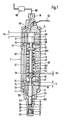
- FIG. 1 shows a Longitudinal section through the fuel injection valve
- Figure 2 an enlarged view of the fuel injection valve in the region of the injection openings
- the figure 3 the schematic Structure of the supply of the fuel injection valve with fuel high pressure and control pressure.
- FIG. 1 shows an enlarged detail Figure 1 shows, and then the operation set forth of the fuel injection valve.
- the fuel injection valve has a multipart valve body 1.
- a combustion chamber side, according to Figure 1 arranged below the valve body 7 is braced with the interposition of a lower washer 14 with a clamping nut 4 against a valve holding body 8.
- a valve connecting body 5 is clamped with the interposition of a valve control body 2 and an upper washer 3 with a clamping nut 6.
- In the valve body 7 is designed as a blind bore bore 11 is formed, which tapers towards the combustion chamber and merges at the combustion chamber end in a slide portion 111.
- a piston-shaped, axially movable valve member 10 is arranged, which is guided with a brennraumabgewandten, upper portion 101 in the bore 11 and tapers toward the combustion chamber to form a pressure shoulder 24, which arranged in a valve member 10 surrounding the pressure chamber 23 is.
- the central section 102 of the valve member 10 which adjoins the upper section 101 on the combustion chamber side, tapers further toward the combustion chamber and merges into a lower section 103.
- a valve sealing surface 25 is formed, which cooperates with a valve seat 26 which is formed by a reduction in cross-section of the bore 11 to the combustion chamber.
- the lower portion 103 of the valve member 10 is the combustion chamber side in a closing head 13 via which the end of Valve member 10 forms.
- the closing head 13 is in the slide portion 111 of the bore 11 sealingly guided and limited a lower hole formed by the blind hole 11 Pressure chamber 20.
- Figure 2 shows an enlarged view of Fuel injection valve in the region of the closing head 13th
- annular channel 28 is formed, which surrounds the valve member 10 over its entire circumference.
- at least one transverse bore 22 is formed in the radial direction and from the transverse bore 22 to the combustion chamber end of the closing head 13 coaxial with the longitudinal axis 38 of the valve member 10, a central bore 21 is formed.
- the transverse bore 22 and the central bore 21 are formed so that they intersect in the valve member 10 and thus establish a connection between the lower pressure chamber 20 and the annular channel 28.
- a control edge 29 is formed at the combustion chamber end of the closing head 13.
- two mutually axially offset injection openings 16,17 are formed in the wall of the slide portion 111 of the bore 11, two mutually axially offset injection openings 16,17 are formed. These are covered by the closing head 13 in the closed state of the fuel injection valve, so that the injection openings 16,17 have neither a connection with the lower pressure chamber 20 nor with the annular channel 28.
- the annular channel 28 and the lower pressure chamber 20 are separated from the pressure chamber 23 when the fuel injection valve is closed by the valve sealing face 25 resting against the valve seat 26.
- the bore 11 is adjoined at the end facing away from the combustion chamber by a spring chamber 36 formed in the valve holding body 8, in which a spring support 40 is formed by a cross-sectional reduction which divides the spring space 36 into a lower spring space 361 and an upper spring space 362.
- the upper portion 101 of the valve member 10 is at the combustion chamber end remote in a smaller diameter intermediate pin 41, which projects through a formed in the lower washer 14 central bore 32 into the lower spring chamber 361.
- the intermediate pin 41 is connected to a arranged in the lower spring chamber 361 spring plate 30, at the end remote from the combustion chamber, a valve stop surface 18 is formed.
- a preferably designed as a helical compression spring closing spring 33 is arranged under bias. It presses the spring plate 30 and thus via the intermediate pin 41, the valve member 10 with the valve sealing surface 25 against the valve seat 26th
- a guide bore 57 is formed, the via a central bore formed in the upper washer 3 64 is connected to the upper spring chamber 362.
- a control piston 43 arranged, consisting essentially of two parts consists of: A hydraulic piston 46, which is in the guide bore 57 is guided, and one with the hydraulic piston 46th connected and from there through the upper spring chamber 362 bis in the lower spring chamber 361 projecting push rod 49th Die Push rod 49 is guided in the spring support 40 and Her brennraum workedes front end is as Hubanschlag
- a control piston stop 58 is formed in the upper spring chamber 362 .
- valve connection body 5 In the valve connection body 5 is a high-pressure fuel connection 78 arranged at which a high pressure feed line 66 opens into the fuel injection valve.
- the high-pressure fuel connection 78 is a in the valve connection body 5, the valve control body 2, the upper washer 3, the Valve holding body 8, the lower washer 14 and the Valve body 7 extending inlet channel 27 with the Pressure chamber 23 connected.
- Fig. 3 the fuel supply system of the fuel injection valves an internal combustion engine with high pressure fuel shown schematically.
- a fuel storage tank 80 gets fuel through a low pressure line 86 fed to a high-pressure fuel pump 82.
- the fuel is under high pressure via a high-pressure line pumped into a high-pressure accumulator 68, where a largely constant high pressure is maintained.
- High-pressure accumulator 68 leads to each fuel injection valve a high pressure feed line 66 via a fuel metering valve 88 and the fuel injector extending inlet channel 27 the pressure chamber 23 with fuel provided.
- the fuel metering valve 88 opens and closes doing the connection from the high pressure feed line 66 to Inlet channel 27 and controls the timing and duration of the opening the injection process.
- the operation of the hydraulically adjustable stroke stop is as follows: If a fuel pressure prevails in the control chamber 56 and the resultant force on the hydraulic piston 46 is greater than the force of the return spring 53, then the hydraulic piston 46 and thus the entire control piston 43 move from a first, upper stroke position, at which the hydraulic piston 46 on the valve connection body 5 is applied to the valve member 10 in a second, lower stroke position until the hydraulic piston 46 abuts the spool stop 58. By this movement, the Hubanschlag substances 44 of the push rod 49 shifts to the valve member 10 and thus reduces the axial distance of Hubanschlag constitutional 44 of the valve stop surface 18 of the valve member 10.
- the stroke stop surface 44 of the push rod 49 also moves away from the valve member 10.
- the control stroke h s is dimensioned such that the axial distance of the Hubanschlag principles 44 of the valve stop surface 18 in this upper stroke position of the control piston 43 is greater than the maximum opening stroke h.
- the operation of the fuel injection valve is as follows: If the fuel metering valve 88 is opened, the pressure of the high-pressure collecting chamber 68 propagates through the inlet channel 27 into the pressure chamber 23. As a result, the resulting force increases in the axial direction of the pressure shoulder 24 until this force is greater than the force of the closing spring 33.
- the valve member 10 lifts with the valve sealing surface 25 from the valve seat 26, whereby the pressure chamber 23 is connected to the annular channel 28 and thus via the transverse bore 22 and the central bore 21 with the lower pressure chamber 20. As soon as the control edge 29 reaches the injection port 17 is Fuel injected via the injection port 17 into the combustion chamber.
- the further course of the opening stroke depends on the stroke position of the control piston 43: If the control piston 43 in the first, upper stroke position, so the valve member 10 passes through the maximum opening stroke h until it comes to rest with the stop shoulder 19 on the stroke stop 15, wherein the Washer 14 the rigidly arranged in the valve body 1 stroke stop 15 forms.
- the combustion chamber facing injection opening 17 and then the combustion chamber facing away from the injection opening 16 is controlled by the control edge 29 first. The injection thus takes place first through the injection opening 17 and then through both injection openings 16, 17 together.
- the closing movement of the valve member 10 takes place when the pressure in the pressure chamber 23 drops so far that the resultant force on the valve member 10 on the pressure shoulder 24, the valve sealing surface 25 and the combustion chamber facing end face of the valve member 10 in the lower pressure chamber 20 is smaller than the force of the closing spring 33 will.
- the valve member 10 is moved by the closing spring 33 in the direction of the combustion chamber until the valve sealing surface 25 comes to rest on the valve seat 26. Thereby, the pressure chamber 23 is separated from the lower pressure chamber 20 and the closing head 13 closes the injection openings 16,17. If, however, the control piston 43 in the lower stroke position, the valve member 10 comes in its opening stroke after passing through the partial stroke h T with the Hubanschlagamide 44 on the valve stop surface 18 to the plant.
- the partial stroke h T is such that the control edge 29 of the closing head 13 at the end of Operahubterrorism between the injection ports 16 and 17, so that only the combustion chamber closer injection port 17 is connected to the pressure chamber 23 and only through the injection port 17 fuel in the Combustion chamber is injected.
- the stop of the valve member 10 on the control piston 43 is thereby hydraulically damped by the control chamber 56.
- the closing movement of the valve member 10 is initiated in the same manner as the closing movement after passing through the maximum opening stroke h.
- the control of the control piston 43 via the pressure in the control line 70 Since in the high pressure accumulator 68 is always a largely constant high pressure fuel can be increased by opening the control valve 73 at any time the fuel pressure in the control line 70 to the pressure in the high pressure accumulator 68. As a result, the control piston 43 moves in the manner described above from the first, upper to the second, lower stroke position and the opening stroke of the valve member 10 is limited to a partial stroke h T of the maximum opening stroke h.
- the partial stroke h T is 40 to 60% of the maximum opening stroke h, preferably about 50%. Relieving the control line 70 via the relief valve 76 in the fuel reservoir tank 80.
- the maximum opening stroke of the valve member 10 is given in the first, upper stroke position of the control piston 43 by the axial distance of Hubanschlag measurements 44 of the valve stop surface 18.
- the control stroke h s and the injection openings 16,17 are formed in this case so that at the maximum opening stroke of the valve member 10, both injection ports are opened.
- the valve member 10 comes in the first, upper stroke position of the control piston 43 at this as a stop to the system, so that the stroke stop 15 can be omitted.
Description
Die Ausgestaltung nach Anspruch 3 weist den Vorteil auf, daß der Maximalhub in einfacher Weise durch Austausch des relativ leicht zugänglichen Steuerkolbens gegen einen mit anderer Höhe geändert werden kann.
Durch den mehrteiligen Aufbau des Steuerkolbens gemäß dem Anspruch 4 ist eine leichte Montierbarkeit des Kraftstoffeinspritzventils gegeben. Je nach Erfordernis an den Aufbau des Kraftstoffeinspritzventils kann gemäß den Ansprüchen 5 und 6 die Rückstellfeder am Hydraulikkolben oder an der Druckstange angreifen, was die Einsetzbarkeit des erfindungsgemäßen hydraulisch veränderbaren Hubanschlags in verschiedenen Kraftstoffeinspritzventilen ermöglicht. Die Ausgestaltung gemäß dem Anspruch 11 weist weiter den Vorteil auf, daß der Einspritzquerschnitt dadurch verringert werden kann, daß die Einspritzöffnung nur zu einem Teil aufgesteuert wird.
Gemäß dem Anspruch 14 ist es in vorteilhafter Weise möglich, die Steuerleitung in sehr kurzer Zeit in den Kraftstoffvorratstank zu entlasten und so den Steuerkolben in die erste Hubposition zu bringen. Es ist also möglich, sehr schnell zwischen Teil- und Maximalhub des Ventilgliedes zu wechseln.
Im Ventilgrundkörper 7 ist eine als Sackbohrung ausgeführte Bohrung 11 ausgebildet, die sich zum Brennraum hin verjüngt und am brennraumseitigen Ende in einen Schieberabschnitt 111 übergeht. In der Bohrung 11 ist ein kolbenförmiges, axial bewegliches Ventilglied 10 angeordnet, das mit einem brennraumabgewandten, oberen Abschnitt 101 in der Bohrung 11 geführt ist und sich zum Brennraum hin unter Bildung einer Druckschulter 24 verjüngt, die in einem das Ventilglied 10 umgebenden Druckraum 23 angeordnet ist.
Der sich an den oberen Abschnitt 101 brennraumseitig anschließende mittlere Abschnitt 102 des Ventilgliedes 10 verjüngt sich zum Brennraum hin weiter und geht in einen unteren Abschnitt 103 über. Am Übergang des mittleren Abschnitts 102 zum unteren Abschnitt 103 des Ventilgliedes 10 ist eine Ventildichtfläche 25 ausgebildet, die mit einem Ventilsitz 26 zusammenwirkt, der durch eine Querschnittsverringerung der Bohrung 11 zum Brennraum hin ausgebildet ist.
In der Wand des Schieberabschnitts 111 der Bohrung 11 sind zwei zueinander axial versetzt angeordnete Einspritzöffnungen 16,17 ausgebildet. Diese werden im geschlossenen Zustand des Kraftstoffeinspritzventils vom Schließkopf 13 überdeckt, so daß die Einspritzöffnungen 16,17 weder eine Verbindung mit dem unteren Druckraum 20 noch mit dem Ringkanal 28 haben. Der Ringkanal 28 und der untere Druckraum 20 sind bei geschlossenem Kraftstoffeinspritzventil durch die am Ventilsitz 26 anliegende Ventildichtfläche 25 vom Druckraum 23 getrennt.
An die Bohrung 11 schließt sich am brennraumabgewandten Ende ein im Ventilhaltekörper 8 ausgebildeter Federraum 36 an, in dem durch eine Querschnittsverringerung eine Federabstützung 40 ausgebildet ist, die den Federraum 36 in einen unteren Federraum 361 und einen oberen Federraum 362 unterteilt. Der obere Abschnitt 101 des Ventilgliedes 10 geht am brennraumabgewandten Ende in einen im Durchmesser kleineren Zwischenstift 41 über, der durch eine in der unteren Zwischenscheibe 14 ausgebildete Zentralbohrung 32 bis in den unteren Federraum 361 ragt. Der Zwischenstift 41 ist mit einem im unteren Federraum 361 angeordneten Federteller 30 verbunden, an dessen brennraumabgewandter Stirnseite eine Ventilanschlagfläche 18 ausgebildet ist. Durch den Übergang des Ventilgliedes 10 zum Zwischenstift 41 ist eine Anschlagschulter 19 ausgebildet und durch den Übergang der Bohrung 11 zur im Durchmesser kleineren Zentralbohrung 32 der Zwischenscheibe 14 ist durch die Zwischenscheibe 14 ein Hubanschlag 15 gebildet. Der axiale Abstand der Anschlagschulter 19 vom Hubanschlag 15 definiert im geschlossenen Zustand des Ventilgliedes 10 den maximalen Öffnungshub h. Zwischen dem Federteller 30 und der Federabstützung 40 ist unter Vorspannung eine vorzugsweise als Schraubendruckfeder ausgebildete Schließfeder 33 angeordnet. Sie drückt den Federteller 30 und damit über den Zwischenstift 41 das Ventilglied 10 mit der Ventildichtfläche 25 gegen den Ventilsitz 26.
Herrscht im Steuerraum 56 ein Kraftstoffdruck, dessen resultierende Kraft auf den Hydraulikkolben 46 größer als die Kraft der Rückstellfeder 53 ist, so bewegt sich der Hydraulikkolben 46 und damit der gesamte Steuerkolben 43 ausgehend von einer ersten, oberen Hubposition, bei der der Hydraulikkolben 46 am Ventilanschlußkörper 5 anliegt, auf das Ventilglied 10 zu in eine zweite, untere Hubposition, bis der Hydraulikkolben 46 am Steuerkolbenanschlag 58 anliegt. Durch diese Bewegung verschiebt sich auch die Hubanschlagfläche 44 der Druckstange 49 auf das Ventilglied 10 zu und verringert so den axialen Abstand der Hubanschlagfläche 44 von der Ventilanschlagfläche 18 des Ventilgliedes 10. In der unteren Hubposition des Steuerkolbens 43 und im geschlossenen Zustand des Ventilgliedes 10 ist der axiale Abstand der Hubanschlagfläche 44 von der Ventilanschlagfläche 18 der Teilhub hT, der kleiner ist als der maximale Öffnungshub h, der durch den axialen Abstand zwischen der Anschlagschulter 19 des Ventilgliedes 10 und dem Hubanschlag 15 gegeben ist. Wird der Kraftstoffdruck im Steuerraum 56 soweit reduziert, daß die resultierende Kraft auf den Hydraulikkolben 46 kleiner als die Kraft der Rückstellfeder 53 ist, so bewegt sich durch die Kraft der Rückstellfeder 53 die Druckstange 49 und damit auch der Hydraulikkolben 46 in Richtung des Ventilanschlußkörpers 5, bis der Hydraulikkolben 46 nach durchfahren des Steuerhubs hs am Ventilanschlußkörper 5 zur Anlage kommt. Dadurch bewegt sich auch die Hubanschlagfläche 44 der Druckstange 49 vom Ventilglied 10 weg. Der Steuerhub hs ist dabei so bemessen, daß der axiale Abstand der Hubanschlagfläche 44 von der Ventilanschlagfläche 18 in dieser oberen Hubposition des Steuerkolbens 43 größer als der maximale Öffnungshub h ist.
Wird das Kraftstoffzumeßventil 88 geöffnet, so breitet sich der Druck des Hochdrucksammelraums 68 durch den Zulaufkanal 27 bis in den Druckraum 23 aus. Dadurch erhöht sich die resultierende Kraft in axialer Richtung auf die Druckschulter 24, bis diese Kraft größer als die Kraft der Schließfeder 33 ist. Das Ventilglied 10 hebt mit der Ventildichtfläche 25 vom Ventilsitz 26 ab, wodurch der Druckraum 23 mit dem Ringkanal 28 verbunden wird und damit auch über die Querbohrung 22 und die Mittelbohrung 21 mit dem unteren Druckraum 20. Sobald die Steuerkante 29 die Einspritzöffnung 17 erreicht, wird Kraftstoff über die Einspritzöffnung 17 in den Brennraum eingespritzt. Der weitere Verlauf der Öffnungshubbewegung hängt von der Hubposition des Steuerkolbens 43 ab: Ist der Steuerkolben 43 in der ersten, oberen Hubposition, so durchfährt das Ventilglied 10 den maximalen Öffnungshub h, bis es mit der Anschlagschulter 19 am Hubanschlag 15 zur Anlage kommt, wobei die Zwischenscheibe 14 den starr im Ventilkörper 1 angeordneten Hubanschlag 15 bildet. Im Verlauf der Öffnungshubbewegung des Ventilgliedes 10 wird durch die Steuerkante 29 zuerst die brennraumzugewandte Einspritzöffnung 17 und dann die brennraumabgewandt versetzt angeordnete Einspritzöffnung 16 aufgesteuert. Die Einspritzung erfolgt also zuerst durch die Einspritzöffnung 17 und dann durch beide Einspritzöffnungen 16,17 gemeinsam. Die Schließbewegung des Ventilgliedes 10 erfolgt dann, wenn der Druck im Druckraum 23 soweit abfällt, daß die resultierende Kraft auf das Ventilglied 10 an der Druckschulter 24, der Ventildichtfläche 25 und der brennraumzugewandten Stirnseite des Ventilgliedes 10 im unteren Druckraum 20 kleiner als die Kraft der Schließfeder 33 wird. Das Ventilglied 10 wird durch die Schließfeder 33 in Richtung auf den Brennraum zu bewegt, bis die Ventildichtfläche 25 am Ventilsitz 26 zur Anlage kommt. Dadurch wird der Druckraum 23 vom unteren Druckraum 20 getrennt und der Schließkopf 13 verschließt die Einspritzöffnungen 16,17.
Ist hingegen der Steuerkolben 43 in der unteren Hubposition, so kommt das Ventilglied 10 bei seiner Öffnungshubbewegung nach durchfahren des Teilhubs hT mit der Hubanschlagfläche 44 an der Ventilanschlagfläche 18 zur Anlage. Dabei ist der Teilhub hT so bemessen, daß die Steuerkante 29 des Schließkopfes 13 beim Ende der Teilhubbewegung zwischen den Einspritzöffnungen 16 und 17 liegt, so daß nur die brennraumnähere Einspritzöffnung 17 mit dem Druckraum 23 verbunden ist und nur durch die Einspritzöffnung 17 Kraftstoff in den Brennraum eingespritzt wird. Der Anschlag des Ventilgliedes 10 am Steuerkolben 43 wird dabei durch den Steuerraum 56 hydraulisch gedämpft. Die Schließbewegung des Ventilgliedes 10 wird auf dieselbe Weise eingeleitet wie die Schließbewegung nach Durchfahren des maximalen Öffnungshubs h.
Claims (14)
- Kraftstoffeinspritzventil für Brennkraftmaschinen mit einem Ventilkörper (1), in dem eine als Sackbohrung ausgeführte Bohrung (11) ausgebildet ist, die brennraumseitig in einen Schieberabschnitt (111) übergeht, an dessen Wand wenigstens eine Einspritzöffnung (16,17) angeordnet ist, und einem in einem brennraumabgewandten Bereich der Bohrung (11) geführten, kolbenförmigen, entgegen der Kraft wenigstens einer Schließfeder (33) axial beweglichen Ventilglied (10), das an seinem brennraumseitigen Ende in einen Schließkopf (13) übergeht, der in dem Schieberabschnitt (111) der Bohrung (11) geführt ist und der die Einspritzöffnung (16,17) verschließt, wobei die Einspritzöffnung (16,17) durch die nach innen gerichtete Öffnungshubbewegung des Ventilgliedes (10) ganz oder teilweise aufsteuerbar ist, wodurch sich der Einspritzquerschnitt abhängig vom Öffnungshub des Ventilgliedes (10) ändert, welches Ventilglied (10) zur Begrenzung seiner Öffnungshubbewegung auf einen maximalen Öffnungshub (h) an einem Anschlag zur Anlage kommt und an welchem eine in Öffnungsrichtung wirkende Druckschulter (24) ausgebildet ist, dadurch gekennzeichnet, daß im brennraumabgewandten Bereich des Ventilkörpers (1) ein Steuerkolben (43) zumindest annähernd koaxial zum Ventilglied (10) angeordnet ist, der in einer im Ventilkörper (1) ausgebildeten Steuerbohrung (57) axial beweglich geführt ist und einen Steuerraum (56) begrenzt, wobei dem Steuerraum (56) unter Druck stehender Kraftstoff zuführbar ist, durch den der Steuerkolben (43) entgegen der Kraft einer Rückstellfeder (53) ausgehend von einer ersten Hubposition auf das Ventilglied (10) zu in eine zweite Hubposition bewegt werden kann, wodurch der Steuerkolben (43) als Anschlag (44) für das Ventilglied (10) wirkt und die Öffnungshubbewegung des Ventilgliedes (10) auf einen Teilhub (hT) begrenzt, der kleiner als der Maximalhub (h) ist.
- Kraftstoffeinspritzventil nach Anspruch 1, dadurch gekennzeichnet, daß der Maximalhub (h) des Ventilgliedes (10) in der ersten Hubposition des Steuerkolbens (43) durch einen starr am Ventilkörper (1) ausgebildeten Hubanschlag (15) gebildet ist.
- Kraftstoffeinspritzventil nach Anspruch 1, dadurch gekennzeichnet, daß der Steuerkolben (43) in seiner ersten Hubposition als Anschlag für das Ventilglied (10) zur Begrenzung von dessen Öffnungshubbewegung auf den maximalen Öffnungshub (h) dient.
- Kraftstoffeinspritzventil nach Anspruch 1, dadurch gekennzeichnet, daß der Steuerkolben (43) zweiteilig aufgebaut ist, wobei ein erster Teil einen Hydraulikkolben (46) bildet und den Steuerraum (56) begrenzt und ein zweiter Teil, der mit dem Hydraulikkolben (46) verbunden ist, als Druckstange (49) ausgebildet ist, die als Anschlag (44) für das Ventilglied (10) dient.
- Kraftstoffeinspritzventil nach Anspruch 4, dadurch gekennzeichnet, daß sich die Rückstellfeder (53) am Hydraulikkolben (46) abstützt.
- Kraftstoffeinspritzventil nach Anspruch 4, dadurch gekennzeichnet, daß sich die Rückstellfeder (53) an der Druckstange (49) abstützt.
- Kraftstoffeinspritzventil nach Anspruch 1, dadurch gekennzeichnet, daß der Steuerkolben (43) in seiner zweiten Hubposition den Öffnungshub des Ventilgliedes (10) auf einen Teilhub (hT) begrenzt, der etwa 40 bis 60 % des maximalen Öffnungshubs (h) beträgt, vorzugsweise etwa 50 %.
- Kraftstoffeinspritzventil nach Anspruch 1, dadurch gekennzeichnet, daß in der Wand der Schieberbohrung (12) wenigstens zwei, zueinander axial versetzt angeordnete Einspritzöffnungen (16,17) ausgebildet sind.
- Kraftstoffeinspritzventil nach Anspruch 8, dadurch gekennzeichnet, daß bei der Begrenzung des Öffnungshubs des Ventilgliedes (10) auf den Teilhub (hT) nur eine Einspritzöffnung (17) aufgesteuert wird.
- Kraftstoffeinspritzventil nach Anspruch 8, dadurch gekennzeichnet, daß der Schließkopf (13) bei maximalem Öffnungshub (h) des Ventilgliedes (10) im Verlauf der Öffnungshubbewegung nacheinander beide Einspritzöffnungen (16,17) aufsteuert.
- Kraftstoffeinspritzventil nach Anspruch 1, dadurch gekennzeichnet, daß der Schließkopf (13) bei einer Begrenzung des Öffnungshubs auf den Teilhub (hT) bei der Öffnungshubbewegung des Ventilgliedes (10) die wenigstens eine Einspritzöffnung (16,17) nur zum Teil aufsteuert.
- Kraftstoffeinspritzventil nach Anspruch 1, dadurch gekennzeichnet, daß das Kraftstoffeinspritzventil über eine Hochdruckzulaufleitung (66) mit einem Hochdrucksammelraum (68) verbunden ist.
- Kraftstoffeinspritzventil nach Anspruch 12, dadurch gekennzeichnet, daß der Steuerraum (56) über eine im Ventilkörper (1) ausgebildete Zulaufbohrung (60) und eine Kraftstoffzulaufleitung (62) mit einer Steuerleitung (70) verbunden ist, die über ein Steuerventil (73) mit dem Hochdrucksammelraum (68) verbunden ist.
- Kraftstoffeinspritzventil nach Anspruch 13, dadurch gekennzeichnet, daß die Steuerleitung (70) über ein Entlastungsventil (76) in einen Kraftstoffvorratstank (80) entlastbar ist.
Applications Claiming Priority (3)
| Application Number | Priority Date | Filing Date | Title |
|---|---|---|---|
| DE19946906A DE19946906A1 (de) | 1999-09-30 | 1999-09-30 | Kraftstoffeinspritzventil für Brennkraftmaschinen |
| DE19946906 | 1999-09-30 | ||
| PCT/DE2000/003019 WO2001023755A1 (de) | 1999-09-30 | 2000-09-02 | Kraftstoffeinspritzventil für brennkraftmaschinen |
Publications (2)
| Publication Number | Publication Date |
|---|---|
| EP1135603A1 EP1135603A1 (de) | 2001-09-26 |
| EP1135603B1 true EP1135603B1 (de) | 2005-02-09 |
Family
ID=7923868
Family Applications (1)
| Application Number | Title | Priority Date | Filing Date |
|---|---|---|---|
| EP00974276A Expired - Lifetime EP1135603B1 (de) | 1999-09-30 | 2000-09-02 | Kraftstoffeinspritzventil für brennkraftmaschinen |
Country Status (6)
| Country | Link |
|---|---|
| US (1) | US6540161B1 (de) |
| EP (1) | EP1135603B1 (de) |
| JP (1) | JP2003510518A (de) |
| BR (1) | BR0007179A (de) |
| DE (2) | DE19946906A1 (de) |
| WO (1) | WO2001023755A1 (de) |
Families Citing this family (18)
| Publication number | Priority date | Publication date | Assignee | Title |
|---|---|---|---|---|
| DE60219396T2 (de) * | 2001-08-06 | 2007-12-20 | Toyota Jidosha Kabushiki Kaisha, Toyota | Brennkraftmaschine |
| DE102004002286A1 (de) * | 2004-01-16 | 2005-08-11 | Man B & W Diesel Ag | Kraftstoffeinspritzdüse |
| DE102005009148A1 (de) * | 2005-03-01 | 2006-09-07 | Robert Bosch Gmbh | Kraftstoffinjektor mit direktgesteuertem Einspritzventilglied mit Doppelsitz |
| DE102007026122A1 (de) | 2007-06-05 | 2008-12-11 | Volkswagen Ag | Kraftstoffeinspritzdüse für eine Brennkraftmaschine |
| ES2340962T3 (es) * | 2007-11-28 | 2010-06-11 | MAGNETI MARELLI S.p.A. | Inyector de carburante con amortiguador mecanico. |
| US8986253B2 (en) | 2008-01-25 | 2015-03-24 | Tandem Diabetes Care, Inc. | Two chamber pumps and related methods |
| DE102008014251A1 (de) * | 2008-03-13 | 2009-09-17 | Man Diesel Se | Einspritzventil für Direkteinspritzung |
| US8408421B2 (en) | 2008-09-16 | 2013-04-02 | Tandem Diabetes Care, Inc. | Flow regulating stopcocks and related methods |
| CA2737461A1 (en) | 2008-09-19 | 2010-03-25 | Tandem Diabetes Care, Inc. | Solute concentration measurement device and related methods |
| AU2010217760B2 (en) | 2009-02-27 | 2015-04-09 | Tandem Diabetes Care, Inc. | Methods and devices for determination of flow reservoir volume |
| US9250106B2 (en) | 2009-02-27 | 2016-02-02 | Tandem Diabetes Care, Inc. | Methods and devices for determination of flow reservoir volume |
| EP2459251B1 (de) | 2009-07-30 | 2014-03-12 | Tandem Diabetes Care, Inc. | Infusionspumpensystem mit einwegkartusche mit druckentlüftung und druckfeedback |
| EP2386745B1 (de) * | 2010-05-11 | 2013-02-13 | Wärtsilä Switzerland Ltd. | Kraftstoffinjektor für Verbrennungsmotoren |
| US9180242B2 (en) | 2012-05-17 | 2015-11-10 | Tandem Diabetes Care, Inc. | Methods and devices for multiple fluid transfer |
| US9173998B2 (en) | 2013-03-14 | 2015-11-03 | Tandem Diabetes Care, Inc. | System and method for detecting occlusions in an infusion pump |
| DE102014211469A1 (de) * | 2014-06-16 | 2015-12-17 | Robert Bosch Gmbh | Düsenbaugruppe für einen Kraftstoffinjektor sowie Kraftstoffinjektor |
| GB2530767A (en) * | 2014-10-01 | 2016-04-06 | Delphi Internat Operations Luxembourg S Ã R L | Fuel injector nozzle |
| JP6453439B2 (ja) * | 2015-03-05 | 2019-01-16 | 日立オートモティブシステムズ株式会社 | 燃料噴射弁、燃料噴射弁の制御装置、及び制御方法 |
Family Cites Families (8)
| Publication number | Priority date | Publication date | Assignee | Title |
|---|---|---|---|---|
| DE2711393A1 (de) * | 1977-03-16 | 1978-09-21 | Bosch Gmbh Robert | Kraftstoffeinspritzduese |
| JPS61149569A (ja) * | 1984-12-21 | 1986-07-08 | Diesel Kiki Co Ltd | 燃料噴射弁 |
| JPH07109181B2 (ja) * | 1986-12-05 | 1995-11-22 | 日本電装株式会社 | 内燃機関用燃料噴射装置 |
| DE3839812A1 (de) * | 1988-11-25 | 1990-05-31 | Bosch Gmbh Robert | Kraftstoff-einspritzduese fuer brennkraftmaschinen |
| DE4005774A1 (de) * | 1990-02-23 | 1991-08-29 | Bosch Gmbh Robert | Kraftstoff-einspritzduese fuer brennkraftmaschinen |
| DE19504849A1 (de) * | 1995-02-15 | 1996-08-22 | Bosch Gmbh Robert | Kraftstoffeinspritzeinrichtung für Brennkraftmaschinen |
| DE19623759A1 (de) * | 1996-06-14 | 1997-12-18 | Bosch Gmbh Robert | Kraftstoffeinspritzventil für Brennkraftmaschinen |
| DE19645900A1 (de) | 1996-11-07 | 1998-05-14 | Bosch Gmbh Robert | Kraftstoffeinspritzventil für Brennkraftmaschinen |
-
1999
- 1999-09-30 DE DE19946906A patent/DE19946906A1/de not_active Withdrawn
-
2000
- 2000-09-02 EP EP00974276A patent/EP1135603B1/de not_active Expired - Lifetime
- 2000-09-02 BR BR0007179-0A patent/BR0007179A/pt not_active IP Right Cessation
- 2000-09-02 US US09/856,970 patent/US6540161B1/en not_active Expired - Fee Related
- 2000-09-02 DE DE50009475T patent/DE50009475D1/de not_active Expired - Lifetime
- 2000-09-02 WO PCT/DE2000/003019 patent/WO2001023755A1/de active IP Right Grant
- 2000-09-02 JP JP2001527113A patent/JP2003510518A/ja active Pending
Also Published As
| Publication number | Publication date |
|---|---|
| EP1135603A1 (de) | 2001-09-26 |
| DE50009475D1 (de) | 2005-03-17 |
| JP2003510518A (ja) | 2003-03-18 |
| US6540161B1 (en) | 2003-04-01 |
| WO2001023755A1 (de) | 2001-04-05 |
| BR0007179A (pt) | 2001-09-04 |
| DE19946906A1 (de) | 2001-04-05 |
Similar Documents
| Publication | Publication Date | Title |
|---|---|---|
| EP1135603B1 (de) | Kraftstoffeinspritzventil für brennkraftmaschinen | |
| EP0779949B1 (de) | Kraftstoffeinspritzeinrichtung für brennkraftmaschinen | |
| DE19519192C1 (de) | Einspritzventil | |
| WO1999002849A1 (de) | Kraftstoffeinspritzvorrichtung | |
| DE4341543A1 (de) | Kraftstoffeinspritzeinrichtung für Brennkraftmaschinen | |
| EP0657643A2 (de) | Kraftstoffeinspritzeinrichtung für Brennkraftmaschinen | |
| DE19921878C2 (de) | Kraftstoffeinspritzsystem für eine Brennkraftmaschine | |
| EP1402174B1 (de) | Kraftstoffeinspritzeinrichtung für eine brennkraftmaschine | |
| EP1483498A1 (de) | Kraftstoffeinspritzeinrichtung für eine brennkraftmaschine | |
| EP1456525A1 (de) | Kraftstoffeinspritzeinrichtung für eine brennkraftmaschine | |
| WO2005014997A1 (de) | Kraftstoff-einspritzvorrichtung für eine brennkraftmaschine | |
| EP1908953B1 (de) | Kraftstoffeinspritzanlage | |
| DE19947196A1 (de) | Kraftstoffeinspritzeinrichtung für Brennkraftmaschinen | |
| WO2010000528A1 (de) | Magnetventil für einen kraftstoff-injektor sowie kraftstoff-injektor | |
| EP0752060B1 (de) | Einspritzventil | |
| EP0915251A2 (de) | Speichereinspritzsystem für eine mehrzylindrige Brennkraftmaschine | |
| WO2001014721A1 (de) | Kraftstoffeinspritzvorrichtung für brennkraftmaschinen | |
| EP1430219A1 (de) | Kraftstoffeinspritzeinrichtung für eine brennkraftmaschine | |
| WO2002093000A1 (de) | Kraftstoffeinspritzsystem | |
| DE3941151A1 (de) | Kraftstoff-einspritzduese fuer brennkraftmaschinen | |
| EP1601870A1 (de) | Kraftstoffeinspritzventil für eine brennkraftmaschine | |
| EP2085604A1 (de) | Injektor zum Einspritzen von Kraftstoff | |
| WO2003052259A1 (de) | Kraftstoffeinspritzeinrichtung für eine brennkraftmaschine | |
| WO2002075149A1 (de) | Kraftstoffeinspritzventil für brennkraftmaschinen | |
| DE10310585A1 (de) | Pumpe-Düse-Einheit |
Legal Events
| Date | Code | Title | Description |
|---|---|---|---|
| PUAI | Public reference made under article 153(3) epc to a published international application that has entered the european phase |
Free format text: ORIGINAL CODE: 0009012 |
|
| AK | Designated contracting states |
Kind code of ref document: A1 Designated state(s): AT BE CH CY DE DK ES FI FR GB GR IE IT LI LU MC NL PT SE |
|
| 17P | Request for examination filed |
Effective date: 20011005 |
|
| RBV | Designated contracting states (corrected) |
Designated state(s): DE FR GB IT |
|
| GRAP | Despatch of communication of intention to grant a patent |
Free format text: ORIGINAL CODE: EPIDOSNIGR1 |
|
| GRAS | Grant fee paid |
Free format text: ORIGINAL CODE: EPIDOSNIGR3 |
|
| GRAA | (expected) grant |
Free format text: ORIGINAL CODE: 0009210 |
|
| AK | Designated contracting states |
Kind code of ref document: B1 Designated state(s): DE FR GB IT |
|
| PG25 | Lapsed in a contracting state [announced via postgrant information from national office to epo] |
Ref country code: IT Free format text: LAPSE BECAUSE OF FAILURE TO SUBMIT A TRANSLATION OF THE DESCRIPTION OR TO PAY THE FEE WITHIN THE PRESCRIBED TIME-LIMIT;WARNING: LAPSES OF ITALIAN PATENTS WITH EFFECTIVE DATE BEFORE 2007 MAY HAVE OCCURRED AT ANY TIME BEFORE 2007. THE CORRECT EFFECTIVE DATE MAY BE DIFFERENT FROM THE ONE RECORDED. Effective date: 20050209 Ref country code: FR Free format text: LAPSE BECAUSE OF NON-PAYMENT OF DUE FEES Effective date: 20050209 Ref country code: GB Free format text: LAPSE BECAUSE OF FAILURE TO SUBMIT A TRANSLATION OF THE DESCRIPTION OR TO PAY THE FEE WITHIN THE PRESCRIBED TIME-LIMIT Effective date: 20050209 |
|
| REG | Reference to a national code |
Ref country code: GB Ref legal event code: FG4D Free format text: NOT ENGLISH |
|
| REG | Reference to a national code |
Ref country code: IE Ref legal event code: FG4D Free format text: GERMAN |
|
| REF | Corresponds to: |
Ref document number: 50009475 Country of ref document: DE Date of ref document: 20050317 Kind code of ref document: P |
|
| GBV | Gb: ep patent (uk) treated as always having been void in accordance with gb section 77(7)/1977 [no translation filed] |
Effective date: 20050209 |
|
| PLBE | No opposition filed within time limit |
Free format text: ORIGINAL CODE: 0009261 |
|
| STAA | Information on the status of an ep patent application or granted ep patent |
Free format text: STATUS: NO OPPOSITION FILED WITHIN TIME LIMIT |
|
| 26N | No opposition filed |
Effective date: 20051110 |
|
| EN | Fr: translation not filed | ||
| PGFP | Annual fee paid to national office [announced via postgrant information from national office to epo] |
Ref country code: DE Payment date: 20091120 Year of fee payment: 10 |
|
| REG | Reference to a national code |
Ref country code: DE Ref legal event code: R119 Ref document number: 50009475 Country of ref document: DE Effective date: 20110401 |
|
| PG25 | Lapsed in a contracting state [announced via postgrant information from national office to epo] |
Ref country code: DE Free format text: LAPSE BECAUSE OF NON-PAYMENT OF DUE FEES Effective date: 20110401 |