EP1134841B1 - Anschlussvorrichtung - Google Patents
Anschlussvorrichtung Download PDFInfo
- Publication number
- EP1134841B1 EP1134841B1 EP01106002A EP01106002A EP1134841B1 EP 1134841 B1 EP1134841 B1 EP 1134841B1 EP 01106002 A EP01106002 A EP 01106002A EP 01106002 A EP01106002 A EP 01106002A EP 1134841 B1 EP1134841 B1 EP 1134841B1
- Authority
- EP
- European Patent Office
- Prior art keywords
- contact
- housing
- individual conductors
- line
- individual
- Prior art date
- Legal status (The legal status is an assumption and is not a legal conclusion. Google has not performed a legal analysis and makes no representation as to the accuracy of the status listed.)
- Expired - Lifetime
Links
- 239000004020 conductor Substances 0.000 claims description 71
- 238000009413 insulation Methods 0.000 claims description 11
- 125000006850 spacer group Chemical group 0.000 claims description 11
- 238000000034 method Methods 0.000 claims description 4
- 238000002955 isolation Methods 0.000 description 8
- 230000035515 penetration Effects 0.000 description 3
- 241000950638 Symphysodon discus Species 0.000 description 2
- 230000015572 biosynthetic process Effects 0.000 description 2
- 238000006073 displacement reaction Methods 0.000 description 2
- 238000005516 engineering process Methods 0.000 description 2
- HOQADATXFBOEGG-UHFFFAOYSA-N isofenphos Chemical compound CCOP(=S)(NC(C)C)OC1=CC=CC=C1C(=O)OC(C)C HOQADATXFBOEGG-UHFFFAOYSA-N 0.000 description 2
- 238000007789 sealing Methods 0.000 description 2
- 208000027418 Wounds and injury Diseases 0.000 description 1
- 238000010276 construction Methods 0.000 description 1
- 230000006378 damage Effects 0.000 description 1
- 230000007423 decrease Effects 0.000 description 1
- 208000014674 injury Diseases 0.000 description 1
- 238000009434 installation Methods 0.000 description 1
- 238000004519 manufacturing process Methods 0.000 description 1
- 239000000463 material Substances 0.000 description 1
- 230000000149 penetrating effect Effects 0.000 description 1
Images



Classifications
-
- H—ELECTRICITY
- H01—ELECTRIC ELEMENTS
- H01R—ELECTRICALLY-CONDUCTIVE CONNECTIONS; STRUCTURAL ASSOCIATIONS OF A PLURALITY OF MUTUALLY-INSULATED ELECTRICAL CONNECTING ELEMENTS; COUPLING DEVICES; CURRENT COLLECTORS
- H01R12/00—Structural associations of a plurality of mutually-insulated electrical connecting elements, specially adapted for printed circuits, e.g. printed circuit boards [PCB], flat or ribbon cables, or like generally planar structures, e.g. terminal strips, terminal blocks; Coupling devices specially adapted for printed circuits, flat or ribbon cables, or like generally planar structures; Terminals specially adapted for contact with, or insertion into, printed circuits, flat or ribbon cables, or like generally planar structures
- H01R12/50—Fixed connections
- H01R12/59—Fixed connections for flexible printed circuits, flat or ribbon cables or like structures
- H01R12/61—Fixed connections for flexible printed circuits, flat or ribbon cables or like structures connecting to flexible printed circuits, flat or ribbon cables or like structures
- H01R12/613—Fixed connections for flexible printed circuits, flat or ribbon cables or like structures connecting to flexible printed circuits, flat or ribbon cables or like structures by means of interconnecting elements
- H01R12/616—Fixed connections for flexible printed circuits, flat or ribbon cables or like structures connecting to flexible printed circuits, flat or ribbon cables or like structures by means of interconnecting elements having contacts penetrating insulation for making contact with conductors, e.g. needle points
-
- H—ELECTRICITY
- H01—ELECTRIC ELEMENTS
- H01R—ELECTRICALLY-CONDUCTIVE CONNECTIONS; STRUCTURAL ASSOCIATIONS OF A PLURALITY OF MUTUALLY-INSULATED ELECTRICAL CONNECTING ELEMENTS; COUPLING DEVICES; CURRENT COLLECTORS
- H01R4/00—Electrically-conductive connections between two or more conductive members in direct contact, i.e. touching one another; Means for effecting or maintaining such contact; Electrically-conductive connections having two or more spaced connecting locations for conductors and using contact members penetrating insulation
- H01R4/24—Connections using contact members penetrating or cutting insulation or cable strands
- H01R4/2404—Connections using contact members penetrating or cutting insulation or cable strands the contact members having teeth, prongs, pins or needles penetrating the insulation
- H01R4/2406—Connections using contact members penetrating or cutting insulation or cable strands the contact members having teeth, prongs, pins or needles penetrating the insulation having needles or pins
-
- H—ELECTRICITY
- H01—ELECTRIC ELEMENTS
- H01R—ELECTRICALLY-CONDUCTIVE CONNECTIONS; STRUCTURAL ASSOCIATIONS OF A PLURALITY OF MUTUALLY-INSULATED ELECTRICAL CONNECTING ELEMENTS; COUPLING DEVICES; CURRENT COLLECTORS
- H01R4/00—Electrically-conductive connections between two or more conductive members in direct contact, i.e. touching one another; Means for effecting or maintaining such contact; Electrically-conductive connections having two or more spaced connecting locations for conductors and using contact members penetrating insulation
- H01R4/24—Connections using contact members penetrating or cutting insulation or cable strands
- H01R4/2416—Connections using contact members penetrating or cutting insulation or cable strands the contact members having insulation-cutting edges, e.g. of tuning fork type
- H01R4/242—Connections using contact members penetrating or cutting insulation or cable strands the contact members having insulation-cutting edges, e.g. of tuning fork type the contact members being plates having a single slot
- H01R4/2425—Flat plates, e.g. multi-layered flat plates
- H01R4/2429—Flat plates, e.g. multi-layered flat plates mounted in an insulating base
- H01R4/2433—Flat plates, e.g. multi-layered flat plates mounted in an insulating base one part of the base being movable to push the cable into the slot
Definitions
- the invention relates to a connection device for connecting a plurality of individual conductors a first line to corresponding individual conductors of a second line with a housing and with a contact part, which according to the principle of Isolation Penetration technique acting contact pins with a cutting edge having more cutting area for contacting the corresponding one another Single conductor has.
- connection device is known from US 5,934,930. She serves For example, for connecting a branch or connecting cable to a supply line. Such a connection device allows a consumer or to connect a device via a branch line to a supply line.
- a connection device allows a consumer or to connect a device via a branch line to a supply line.
- US 5,934,930 is a first Line or supply line between a contact part and an upper housing part and a second line or branch line between a lower housing part and the contact part inserted.
- the two lines each have several individual conductors, which via conical contact pins on the principle of Isolations matdringungstechnik be contacted.
- the contact pins protrude on both sides out of the contact part.
- For fixing the individual conductors of the branch line has the lower housing part grooves, in which the individual conductors are inserted.
- the contact part has correspondingly shaped webs, which are in the grooves engage the housing base and thus fix the individual conductors in their position. This is to ensure that the individual conductors in their position when contacting are held so that they are the conically shaped contact tip can not escape when contacting.
- the invention has for its object to provide a connection device, which allows a secure contact.
- a connecting device for connecting a plurality of individual conductors of a first line to corresponding Single conductor of a second line with a housing and with a contact part, which acting on the principle of Isolations matdringungstechnik pins for contacting the corresponding individual conductors, wherein the contact pins have a cutting area with a cutting edge.
- the contact pins continue to have at least one contact area, which in the contacted state with the single conductor is in contact, perpendicular to their Longitudinal axis of an elongated and elliptical in particular cross-sectional area.
- the contact pin is preferably ellipsoidal or as an elongated discus educated.
- the proposed here pins have an elongated cutting edge on.
- the contact pin penetrates into the Ladder core of the individual conductor, wherein the conductor core in particular a bundle of having individual stranded wires.
- the pins therefore differ from so-called cutting contacts, in which only the insulation of the individual conductor is severed.
- the elongated cutting edge has the significant advantage that the to be contacted Single conductor cut in its longitudinal direction and its individual Stranded wires are displaced only slightly laterally. This lateral Repression is compared to the repression of a cone point is caused, low. The stranded wires are therefore in the contacting significantly less stressed. Furthermore, because of the elongated Cutting edge of the individual conductors to be contacted better when contacting, so that the risk of dodging of the conductor is reduced and thus a safe Contacting is guaranteed.
- the cutting edge has a backward extending area and is in particular rounded.
- the cutting edge is So bent to the single conductor out, so that only a portion the cutting edge cuts the single conductor.
- the cutting edge gradually penetrates the single conductor, wherein the insulation is cut open gradually. Essential is that thereby an actual cutting takes place, whereas in the conventional conical contact tips, the tip is merely pressed and the material is displaced on all sides. Because of the gradual decline in the individual conductors are the forces necessary for contacting low. This is especially advantageous if multi-core cables are contacted.
- the cutting area is discusiform formed, in the sense of a particular curved on both sides Disc.
- the edge of the disc need not necessarily be formed as a circle but may also be elliptical or egg-shaped.
- the discus type Training the cutting area allows a gentle contact with relatively little effort. The gentle contact is essential influenced by the symmetrical and in particular rounded training.
- a shaft connects to the cutting area with a dull, especially slightly rounded side edge.
- the flat trained contact pin is thus at its substantially parallel Side edges not sharp-edged. This is the risk of unwanted Damage or severing of individual stranded wires of the Single conductor when entering and penetrating the contact pin low.
- the contact pins with two opposite Cutting areas formed and protrude on both sides of the contact part, which is arranged between an upper housing part and a lower housing part is, so that the two lines to be contacted with each other to be ordered.
- An alternative embodiment with juxtaposed lines is without limiting the function of the contact pins also to realize and leads to a flat construction.
- the housing has the housing-side guide the contact pins on recesses, which correspond to one of the contact pins Have geometry.
- the contact pins thus penetrate the individual conductors completely and range in the contacted state of the contact part to the housing, where their tips, ie their cutting areas, are guided or held.
- the contact pins are different designed to contact different types of To enable individual leaders.
- a connection device with such contact pins is particularly suitable, for example, for combined data and Power lines used to connect electrical consumers be addressed, for example, the consumers via a data bus system and be powered simultaneously via the combined line.
- the different design of the pins can also be independent of realize the special shape of the cutting area, so is also for the known conical contact pins suitable.
- At least one contact pin is preferably subdivided into a plurality of functional zones. This allows a targeted and secure contact of special single conductors, which are multi-layered or multi-shelled.
- the contact pin on a contact zone which of a Isolation zone is surrounded.
- This is advantageously an undesirable conductive connection via the contact pin between different areas prevents such a special single conductor.
- the contact pin is thereby for contacting a shield having individual conductor provided, wherein the isolation zone and the contact zone are arranged such that in the contacting state, the contact zone with the conductor core of the individual conductor is in contact and this particular complete covered and that the isolation zone completely covers the shield. This is a short circuit between the shield and the conductor core safely prevented.
- the contact part has webs, the one bearing surface for spacers between adjacent individual conductors form the lines.
- These spacers are for example at Ribbon cables formed by the insulation between the individual conductors.
- These spacers are spacers in so-called Steg Oberen formed in which the conductors spaced from each other via the spacer webs being held.
- the lines are in an expedient embodiment between two adjacent webs in each case a receptacle for one of Single ladder formed.
- the cross-sectional profile of the receptacle the cross-sectional profile of the first and second line in the region of adapted to each individual member.
- the cross-sectional profile is preferred the webs the cross-sectional profile of the first and second line in the area adapted to the spacers.
- the housing preferably to the webs of the contact part corresponding equivalent webs.
- this has a three-part housing 4, through which a first line, for example a Supply line 6 is guided.
- a second line, for example a branch line 8 opens into the connection device 2.
- the two lines 6.8 are executed in the embodiment each as a multi-core ribbon cable.
- the supply line 6 has a plurality of individual conductors 10A to 10D and the branch line 8 has for this purpose corresponding individual conductors 12A to 12D.
- about the connecting device 2 are the corresponding individual conductors, For example, the single conductor 10A to the single conductor 12A conductively connected.
- the supply line is used for contacting 6 between a lower housing part 14 and a middle part of the housing 16, and the branch line 8 between the middle part 16 and a housing upper part 18 inserted.
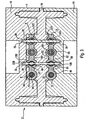
- the housing middle part 16 has a contact part 20, from the multiple contact pins 22 projecting on both sides (see also Fig. 3).
- the housing parts 14,16 and 18 each have openings 24 at their front sides for the supply line 6 and the branch line 8 on. Because the branch line 8 does not extend through the housing 4, has the upper part of Housing middle part 16 and the upper housing part 18 only an end opening 24.
- the middle part 16 has locating pins 26, both in the direction of the upper housing part 18 and the housing lower part 14 occidentalrekken and there with closed housing 4 in corresponding positioning recesses 28 grab.
- each locking recesses 30 are provided in the corresponding locking pin 32 of the housing middle part 16 engage.
- the contact part 20 has, for each corresponding pair of conductors, e.g. 10A, 12A a contact pin 22. There may also be several contact pins per pair of conductors 10A, 12A 22 may be provided.
- the contact pins 22 are in the longitudinal direction 23, along the lines 6,8 are guided through the housing 4, offset, where, for example, individual pairs are provided at the same height.
- the staggered arrangement causes the individual conductors 12A to 12D to be different Places contacted with respect to the longitudinal direction 23 and displaced laterally become.
- adjacent contact pins 22 offset wherein the first and the third and the second and the fourth contact pin each form a pair, which is arranged at the same height.
- Detect pins 22B and 22D are arranged on the contact part 20, which forms a partial region of the housing middle part 16.
- the contact pins 22nd are perpendicular to the contact part 20 and have at their opposite Each ends a cutting region 36 with a cutting edge 38.
- the between The cutting portions 36 lying part of the contact pin 22 is used as a shaft 40 denotes.
- the contact pins penetrate 22B, D, the individual conductors 10B, D and 12B, D respectively complete, wherein the cutting region 36 each in a recess 39 of the upper housing part 18th or the housing lower part 14 extends.
- These recesses 39 are preferably adapted to the geometry of the cutting region 36 and in particular slit-shaped, so that the contact pins 22 in the two housing parts 14,18 are performed.
- the individual conductors 10, 12 of the two cables 6, 8 designed as ribbon cables have a Leiterkem 44 surrounded by an insulation 42, which, for example is formed of a bundle of individual stranded wires.
- the individual leaders 10A, B, 12A, B are designed as data conductors and additionally have one Shield 46 on.
- the two other individual conductor types C, D are used in particular the power supply.
- To form the ribbon cable are the individual conductors 10,12 surrounded by a common insulating jacket 48, wherein between adjacent individual conductors 10, 12 each spacer webs 50 are provided, which serve to separate the individual conductors 10,12 from each other.
- the contact pin 22B which is for contacting the shielded individual conductors 10B, 12B is divided into several functional zones. He points to each one Einzelleiters 10B, 12B each have a contact area forming a contact zone 47th on, which is surrounded by two isolation zones 49.
- the contact zone 47 covers the conductor core 44, and the isolation zones 49 cover the area of Shield 46, so that a short circuit between the shield 46 and the Laderkem 44 is avoided.
- the isolation zone 49 is for example through the Application, in particular sticking, of insulation strips on the base body formed of the contact pin 22, wherein the base body of a conductive material consists.
- the cross-sectional contours of the contact part 20 and the lower housing part 14 and of the upper housing part 18 are the cross-sectional contour of the two lines 6,8 customized.
- webs 52 are provided, between which the spacer webs 50 are clamped in the assembled state.
- the webs 52 preferably have on their front side in each case a trough-like depression and form a receptacle 54 for the spacer bars.
- the side surfaces of the webs 52 extend arcuate, with adjacent side surfaces another receptacle 56 form. Between two opposite further receptacles 56 are the individual conductors 10,12 clamped.
- the contoured design of the Contact part 20 and the housing parts 14,18 ensures that the two lines 6.8 safe and strong - for example, in a tensile stress - in the housing 4 are held.
- the contoured or profiled design works in particular as an abutment for magnetic or electromagnetic forces at high currents occur and which tend to contact pins 22 of to repel the individual leaders 10,12.
- the webs 52 may have a rectangular profile, so that of the webs 52 and the receptacles 56 a crenellated Contour is formed.
- This crenellated contour is easy to make and leads also to a good grip of the lines 6,8, although the stop at the rounded, adapted to the cross-sectional contour of the lines 6.8 execution is better.
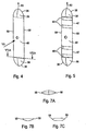
- the particular configuration of the contact pins 22 is best exemplified in Figures 4 and 5 shown. It can be seen that the contact pins 22 are substantially flat structures, being at the opposite ends of the shaft 40 each have a discus-shaped ausgestalteter cutting area 36 is located. The edge of the disk-like cutting area 36 forms the cutting edge 38.
- the contact pin 22 has a total of an elongated discus-like Shape or even a flat ellipsoidal shape with parallel and preferably blunt side edges 58.
- the contact pin 22 has two major design features, namely the elongated design of the cutting edge 38 and the flat configuration the contact pin 22 at least in the contact area or in the contact zone 47, in in or in the conductor core 44 with the contact pin 22 in the contacted state communicates.
- Cutting edge 38 it should be mentioned that it is particularly due to in the direction of the shaft 40 rearwardly bent training as Cutting edge acts like a knife and thus for a comparatively simple Penetration of the contact pin 22 in the individual conductors 10,12 provides. this means at the same time that the force required to contact is low. Another The point of view of the elongated cutting edge 38 is in comparison to a punctiform tip better guidance in relation to each individual leader 10.12 to see. The individual conductors 10,12 do not dodge and are contacted safely.
- the cutting edge 38 is semicircular. Instead of the semicircular training, the cutting edge can also be on a non-circular curved line lie.
- the curved design of the cutting edge 38 is the preferred embodiment, as with this embodiment, a gradual and uniform cutting of the contact pin 22 in the individual conductors 10,12 without particularly high effort is possible.
- the cutting edge 38 is alternatively as a polygon, as exemplified in Fig. 6B is shown formed. This is manufacturing technology relatively easy to implement. In the simplest case, the cutting edge 38 is knife-like as a straight line educated. An improved over this simplest version Design is shown in FIG. 6C, in which a flat knife-like edge 62 passes over slopes 64 in the shaft 40.
- the key advantage of the flat design is that the individual conductors 10,12 be cut longitudinally, and that their individual stranded wires only slightly displaced laterally. Their claim is therefore low.
- the preferred is configured in approximately ellipse-like or lenticular, as shown in FIG. 7A is found, a very high contact area with the to be contacted Single conductor 10,12 achieved with only a very small lateral displacement.
- the Contact safety is thus very high or in other words, the contact resistance between the contact pin 22 and the respective individual conductor 10,12 is very low.
- connection device 2 described is characterized by several design features which, in combination, makes for a particularly secure contact lead the two lines 6,8 together. These are essentially the special configuration of the contact pins 22 with respect to their geometric Shape as well as its subdivision into several functional zones. As another essential Feature is the contoured design of the contact part 20 and the Housing bottom 14 and the housing top 18 to see.
- the preferred ellipsoidal Configuration of the contact pins 22, their subdivision into functional zones 47,49 as well as the contouring are aspects, which also individually and in particular independently advantageous embodiments of a connection device represent.
Landscapes
- Coupling Device And Connection With Printed Circuit (AREA)
- Multi-Conductor Connections (AREA)
- Connector Housings Or Holding Contact Members (AREA)
Description
Dies ermöglicht eine gezielte und sichere Kontaktierung von speziellen Einzelleitern, die mehrschichtig oder mehrschalig aufgebaut sind.
- Fig. 1
- eine Anschlussvorrichtung mit verschlossenem Gehäuse mit einer Versorgungsleitung und einer Abzweigungsleitung,
- Fig. 2
- die Anschlussvorrichtung nach Fig. 1 in einer Explosionsdarstellung,
- Fig. 3
- die Anschlussvorrichtung in einer Schnittansicht,
- Fig. 4
- einen ellipsoidartig ausgebildeten Kontaktstift,
- Fig. 5
- einen ellipsoidartig ausgebildeten Kontaktstift mit mehreren Funktionszonen,
- Fig. 6A
- eine Schnittansicht des Schnitts 6A-6A durch den Kontaktstift parallel zu dessen Längsachse gemäß Fig. 4,
- Fig. 6B,C
- alternative Schnittgeometrien zu der in Fig. 6A Dargestellten,
- Fig. 7A
- eine Schnittansicht des Schnitts 7A-7A durch den Kontaktstift senkrecht zu dessen Längsachse gemäß Fig. 4,
- Fig. 7B,C
- alternative Schnittgeometrien zu den in Fig. 7A Dargestellten.
- 2
- Anschlussvorrichtung
- 4
- Gehäuse
- 6
- Versorgungsleitung
- 8
- Abzweigleitung
- 10A-D
- Einzelleiter
- 12A-D
- Einzelleiter
- 14
- Gehäuseunterteil
- 16
- Gehäusemittelteil
- 18
- Gehäuseoberteil
- 20
- Kontaktteil
- 22
- Kontaktstifte
- 23
- Längsrichtung
- 24
- Öffnung
- 26
- Positionierzapfen
- 28
- Positionierausnehmung
- 30
- Rastausnehmung
- 32
- Rastzapfen
- 34
- Dichtsteg
- 36
- Schneidbereich
- 38
- Schneidkante
- 39
- Ausnehmung
- 40
- Schaft
- 42
- Isolierung
- 44
- Leiterkem
- 46
- Abschirmung
- 47
- Kontaktzone
- 48
- Isolationsmantel
- 49
- Isolationszone
- 50
- Distanzsteg
- 52
- Steg
- 54
- Aufnahmewanne
- 56
- weitere Aufnahmewanne
- 58
- Seitenkante
- 60
- Längsachse
- 62
- Kante
- 64
- Schräge
Claims (15)
- Anschlussvorrichtung (2) zum Anschließen mehrerer Einzelleiter (10) einer ersten Leitung (6) an korrespondierende Einzelleiter (12) einer zweiten Leitung (8) mit einem Gehäuse (4) und mit einem Kontaktteil (20), welches nach dem Prinzip der Isolationsdurchdringungstechnik wirkende Kontaktstifte (22) mit einem eine Schneidkante (38) umfassenden Schneidbereich (36) zur Kontaktierung der einander korrespondierenden Einzelleiter (10A,12A) aufweist,
dadurch gekennzeichnet, dass zumindest in einem Kontaktbereich (47) die Kontaktstifte (22) senkrecht zu ihrer Längsachse (60) eine langgestreckte und ellipsenartige Querschnittsfläche aufweisen. - Vorrichtung (2) nach Anspruch 1,
dadurch gekennzeichnet, dass die Schneidkante (38) einen sich rückwärtig erstreckenden Bereich aufweist und insbesondere gerundet ist. - Vorrichtung (2) nach Anspruch 1 oder 2,
dadurch gekennzeichnet, dass der Schneidbereich (38) diskusförmig ausgebildet ist. - Vorrichtung (2) nach einem der vorhergehenden Ansprüche,
dadurch gekennzeichnet, dass sich an den Schneidbereich (36) ein Schaft (40) mit einer stumpfen Seitenkante (58) anschließt. - Vorrichtung (2) nach einem der vorhergehenden Ansprüche,
dadurch gekennzeichnet, dass die Kontaktstifte (22) mit zwei einander gegenüberliegenden Schneidbereichen (36) ausgebildet sind und beidseitig aus dem Kontaktteil (20) herausragen, welches zwischen einem Gehäuseoberteil (18) und einem Gehäuseunterteil (14) angeordnet ist. - Vorrichtung (2) nach einem der vorhergehenden Ansprüche,
dadurch gekennzeichnet, dass das Gehäuse (4) zur gehäuseseitigen Führung der Kontaktstifte (22) Ausnehmungen (39) aufweist, die eine zu den Kontaktstiften (22) korrespondierende Geometrie haben. - Vorrichtung (2) nach einem der vorhergehenden Ansprüche,
dadurch gekennzeichnet, dass unterschiedlich ausgebildete Kontaktstifte (22B,22D) zur Kontaktierung unterschiedlicher Arten von Einzelleitern (10B,12B;10D,12D) vorgesehen sind. - Vorrichtung (2) nach einem der vorhergehenden Ansprüche,
dadurch gekennzeichnet, dass zumindest ein Kontaktstift (22B) in mehrere Funktionszonen (47,49) unterteilt ist. - Vorrichtung (2) nach Anspruch 8,
dadurch gekennzeichnet, dass der Kontaktstift (22B) eine Kontaktzone (47) aufweist, die von einer Isolationszone (49) umgeben ist. - Vorrichtung (2) nach Anspruch 9,
dadurch gekennzeichnet, dass der Kontaktstift (22B) zur Kontaktierung eines eine Abschirmung (46) aufweisenden Einzelleiters (10B,12B) vorgesehen ist, wobei die Isolationszone (49) und die Kontaktzone (47) derart angeordnet sind, dass im Kontaktierungszustand die Kontaktzone (47) mit dem Leiterkem (44) des Einzelleiters (10B,12B) in Berührung ist, und dass die Isolationszone (49) die Abschirmung (46) vollständig überdeckt. - Vorrichtung (2) nach einem der vorhergehenden Ansprüche,
dadurch gekennzeichnet, dass das Kontaktteil (20) Stege (52) aufweist, die eine Auflagefläche für zwischen benachbarten Einzelleitern (10,12) angeordnete Distanzstücke (50) der Leitungen (6,8) bilden. - Vorrichtung (2) nach Anspruch 11,
dadurch gekennzeichnet, dass zwischen zwei benachbarten Stegen (52) jeweils eine Aufnahmewanne (56) für einen der Einzelleiter (10,12) gebildet ist. - Vorrichtung (2) nach Anspruch 12,
dadurch gekennzeichnet, dass das Querschnittsprofil der Aufnahmewanne (56) dem Querschnittsprofil der ersten Leitung (6) bzw. der zweiten Leitung (8) im Bereich der jeweiligen Einzelleiter (10,12) angepasst ist. - Vorrichtung (2) nach einem der Ansprüche 11 bis 13,
dadurch gekennzeichnet, dass das Querschnittsprofil der Stege (52) dem Querschnittsprofil der ersten Leitung (6) bzw. der zweiten Leitung (8) im Bereich der jeweiligen Distanzstücke (50) angepasst ist. - Vorrichtung (2) nach einem der Ansprüche 11 bis 14,
dadurch gekennzeichnet, dass das Gehäuse (4) zu den Stegen (52) des Kontaktteils (20) korrespondierende gleichwirkende Stege (52) aufweist.
Priority Applications (1)
| Application Number | Priority Date | Filing Date | Title |
|---|---|---|---|
| DE20122498U DE20122498U1 (de) | 2000-03-13 | 2001-03-10 | Anschlussvorrichtung |
Applications Claiming Priority (2)
| Application Number | Priority Date | Filing Date | Title |
|---|---|---|---|
| DE10012177 | 2000-03-13 | ||
| DE10012177A DE10012177A1 (de) | 2000-03-13 | 2000-03-13 | Anschlussvorrichtung |
Publications (3)
| Publication Number | Publication Date |
|---|---|
| EP1134841A2 EP1134841A2 (de) | 2001-09-19 |
| EP1134841A3 EP1134841A3 (de) | 2002-11-20 |
| EP1134841B1 true EP1134841B1 (de) | 2005-12-21 |
Family
ID=7634541
Family Applications (1)
| Application Number | Title | Priority Date | Filing Date |
|---|---|---|---|
| EP01106002A Expired - Lifetime EP1134841B1 (de) | 2000-03-13 | 2001-03-10 | Anschlussvorrichtung |
Country Status (3)
| Country | Link |
|---|---|
| EP (1) | EP1134841B1 (de) |
| DE (3) | DE10012177A1 (de) |
| ES (1) | ES2254275T3 (de) |
Families Citing this family (5)
| Publication number | Priority date | Publication date | Assignee | Title |
|---|---|---|---|---|
| DE20102589U1 (de) | 2001-02-14 | 2001-05-10 | Mazur-Schaar, Bernd, 82166 Gräfelfing | Vorrichtung zum Anschluß elektrischer Bauteile an Kabellitzen |
| DE20114781U1 (de) | 2001-09-06 | 2001-12-06 | ASPÖCH Systems Fahrzeugelektrik Ges. m.b.H. & Co. KG, Peuerbach | Kabelverzweiger |
| DE10213673A1 (de) * | 2002-03-27 | 2003-10-09 | Hella Kg Hueck & Co | Verbindungselement |
| DE102007041814A1 (de) | 2007-09-03 | 2009-03-05 | Woertz Ag | Vorrichtung zur abisolierfreien Herstellung eines Anschlusses an ein Flachkabel |
| DE102007041815B4 (de) * | 2007-09-03 | 2009-07-09 | Woertz Ag | Vorrichtung zur abisolierfreien Herstellung eines Anschlusses an ein Flachkabel |
Family Cites Families (6)
| Publication number | Priority date | Publication date | Assignee | Title |
|---|---|---|---|---|
| JPH0721971B2 (ja) * | 1987-03-18 | 1995-03-08 | 住友電気工業株式会社 | 多重伝送用ケ−ブル |
| FR2665803B1 (fr) * | 1990-08-09 | 1993-06-18 | Labinal | Connecteur de derivation. |
| DE9214675U1 (de) * | 1992-10-29 | 1994-03-03 | Robert Bosch Gmbh, 70469 Stuttgart | Elektrische Anschluß-Vorrichtung an einem ein- oder mehradrigen Kabel |
| US5498172A (en) * | 1993-07-30 | 1996-03-12 | Sunx Kabushiki Kaisha | Electrical connector for interconnecting parallel multiconductor cables |
| FR2750802B1 (fr) * | 1996-07-02 | 1998-09-18 | Pouyet Sa | Procede et dispositif d'interconnexion rapide de deux cables electriques |
| RU2145756C1 (ru) * | 1998-09-11 | 2000-02-20 | Раков Дмитрий Леонидович | Способ соединения электрических элементов и устройство для его осуществления |
-
2000
- 2000-03-13 DE DE10012177A patent/DE10012177A1/de not_active Withdrawn
-
2001
- 2001-03-10 DE DE50108421T patent/DE50108421D1/de not_active Expired - Fee Related
- 2001-03-10 ES ES01106002T patent/ES2254275T3/es not_active Expired - Lifetime
- 2001-03-10 DE DE20122498U patent/DE20122498U1/de not_active Expired - Lifetime
- 2001-03-10 EP EP01106002A patent/EP1134841B1/de not_active Expired - Lifetime
Also Published As
| Publication number | Publication date |
|---|---|
| EP1134841A2 (de) | 2001-09-19 |
| DE50108421D1 (de) | 2006-01-26 |
| EP1134841A3 (de) | 2002-11-20 |
| DE10012177A1 (de) | 2001-10-31 |
| ES2254275T3 (es) | 2006-06-16 |
| DE20122498U1 (de) | 2005-12-29 |
Similar Documents
| Publication | Publication Date | Title |
|---|---|---|
| DE2941029C2 (de) | ||
| DE69006608T2 (de) | Stromschiene als Zwischenschicht in einer Steckvorrichtung. | |
| DE3127704C2 (de) | Verbinder zum Anschließen eines Vielleiter-Flachkabels | |
| DE69226879T2 (de) | Elektrische Verbinder | |
| DE2735838C2 (de) | Elektrische Anschlußklemme und elektrisches Kabelverbindungsglied | |
| DE69029863T2 (de) | Erdungsklemme von der art der isolationsverdrängung | |
| DE2547166A1 (de) | Elektrische verbinderanordnung | |
| DE3623258A1 (de) | Anschlusswerkzeug zum einsetzen von draehten oder litzen in loetstellenfreie verbinder | |
| EP0817314A2 (de) | Anschlussvorrichtung für Schneidkontakt | |
| EP0650217B1 (de) | Leiteranschlussvorrichtung für Schwachstromanlagen | |
| DE3313284C2 (de) | Elektrischer Stecker | |
| DE20122498U1 (de) | Anschlussvorrichtung | |
| DE10209708A1 (de) | Elektrischer Verbinder | |
| EP0267145B1 (de) | Schneidklemm-Anschlusselement für elektrische Leiter | |
| DE4320539C2 (de) | Leitungsdraht-Verbindungsklemme | |
| DE19936347C2 (de) | Selbsttätig isolationsdurchdringendes Verbindungsstück | |
| DE19807938A1 (de) | Steckverbinder bestehend aus einem Gehäuse und mindestens einem Kontakt | |
| DE2525221A1 (de) | Elektrische reihenverbindungsanordnung | |
| DE102009040646B3 (de) | Vorrichtung zum Abtrennen eines Brückensteges eines Steckbrückensystems | |
| DE3339313A1 (de) | Stecker fuer schwachstromanlagen | |
| DE9304392U1 (de) | Kontaktelement mit Schneidklemm- und Crimpanschluß | |
| EP0834957A1 (de) | Einrichtung zur elektrischen Verbindung von mindestens zwei mehradrigen, vorzugsweise zweiadrigen Leitern | |
| DE2827849C2 (de) | ||
| DE3890562C2 (de) | Anschlußklemmleiste zum Verbinden einer Leitungsader aus einer Vielzahl ankommender, isolierter Leitungsadern mit jeweils einer Leitungsader aus einer Vielzahl von abgehenden, isolierten Leitungsadern | |
| DE10205613B4 (de) | Kontaktelement |
Legal Events
| Date | Code | Title | Description |
|---|---|---|---|
| PUAI | Public reference made under article 153(3) epc to a published international application that has entered the european phase |
Free format text: ORIGINAL CODE: 0009012 |
|
| AK | Designated contracting states |
Kind code of ref document: A2 Designated state(s): AT BE CH CY DE DK ES FI FR GB GR IE IT LI LU MC NL PT SE TR |
|
| AX | Request for extension of the european patent |
Free format text: AL;LT;LV;MK;RO;SI |
|
| PUAL | Search report despatched |
Free format text: ORIGINAL CODE: 0009013 |
|
| AK | Designated contracting states |
Kind code of ref document: A3 Designated state(s): AT BE CH CY DE DK ES FI FR GB GR IE IT LI LU MC NL PT SE TR |
|
| AX | Request for extension of the european patent |
Free format text: AL;LT;LV;MK;RO;SI |
|
| 17P | Request for examination filed |
Effective date: 20030115 |
|
| AKX | Designation fees paid |
Designated state(s): AT BE CH CY DE DK LI |
|
| RBV | Designated contracting states (corrected) |
Designated state(s): DE ES FR GB IT NL |
|
| 17Q | First examination report despatched |
Effective date: 20041005 |
|
| GRAP | Despatch of communication of intention to grant a patent |
Free format text: ORIGINAL CODE: EPIDOSNIGR1 |
|
| GRAS | Grant fee paid |
Free format text: ORIGINAL CODE: EPIDOSNIGR3 |
|
| GRAA | (expected) grant |
Free format text: ORIGINAL CODE: 0009210 |
|
| AK | Designated contracting states |
Kind code of ref document: B1 Designated state(s): DE ES FR GB IT NL |
|
| REG | Reference to a national code |
Ref country code: GB Ref legal event code: FG4D Free format text: NOT ENGLISH |
|
| REF | Corresponds to: |
Ref document number: 50108421 Country of ref document: DE Date of ref document: 20060126 Kind code of ref document: P |
|
| GBT | Gb: translation of ep patent filed (gb section 77(6)(a)/1977) |
Effective date: 20060313 |
|
| REG | Reference to a national code |
Ref country code: ES Ref legal event code: FG2A Ref document number: 2254275 Country of ref document: ES Kind code of ref document: T3 |
|
| ET | Fr: translation filed | ||
| PLBE | No opposition filed within time limit |
Free format text: ORIGINAL CODE: 0009261 |
|
| STAA | Information on the status of an ep patent application or granted ep patent |
Free format text: STATUS: NO OPPOSITION FILED WITHIN TIME LIMIT |
|
| 26N | No opposition filed |
Effective date: 20060922 |
|
| PGFP | Annual fee paid to national office [announced via postgrant information from national office to epo] |
Ref country code: ES Payment date: 20080326 Year of fee payment: 8 |
|
| PGFP | Annual fee paid to national office [announced via postgrant information from national office to epo] |
Ref country code: GB Payment date: 20080318 Year of fee payment: 8 |
|
| PGFP | Annual fee paid to national office [announced via postgrant information from national office to epo] |
Ref country code: DE Payment date: 20080331 Year of fee payment: 8 Ref country code: FR Payment date: 20080314 Year of fee payment: 8 |
|
| PGFP | Annual fee paid to national office [announced via postgrant information from national office to epo] |
Ref country code: IT Payment date: 20080329 Year of fee payment: 8 |
|
| PGFP | Annual fee paid to national office [announced via postgrant information from national office to epo] |
Ref country code: NL Payment date: 20080318 Year of fee payment: 8 |
|
| GBPC | Gb: european patent ceased through non-payment of renewal fee |
Effective date: 20090310 |
|
| NLV4 | Nl: lapsed or anulled due to non-payment of the annual fee |
Effective date: 20091001 |
|
| REG | Reference to a national code |
Ref country code: FR Ref legal event code: ST Effective date: 20091130 |
|
| PG25 | Lapsed in a contracting state [announced via postgrant information from national office to epo] |
Ref country code: DE Free format text: LAPSE BECAUSE OF NON-PAYMENT OF DUE FEES Effective date: 20091001 |
|
| PG25 | Lapsed in a contracting state [announced via postgrant information from national office to epo] |
Ref country code: NL Free format text: LAPSE BECAUSE OF NON-PAYMENT OF DUE FEES Effective date: 20091001 |
|
| PG25 | Lapsed in a contracting state [announced via postgrant information from national office to epo] |
Ref country code: FR Free format text: LAPSE BECAUSE OF NON-PAYMENT OF DUE FEES Effective date: 20091123 Ref country code: GB Free format text: LAPSE BECAUSE OF NON-PAYMENT OF DUE FEES Effective date: 20090310 |
|
| REG | Reference to a national code |
Ref country code: ES Ref legal event code: FD2A Effective date: 20090311 |
|
| PG25 | Lapsed in a contracting state [announced via postgrant information from national office to epo] |
Ref country code: ES Free format text: LAPSE BECAUSE OF NON-PAYMENT OF DUE FEES Effective date: 20090311 |
|
| PG25 | Lapsed in a contracting state [announced via postgrant information from national office to epo] |
Ref country code: IT Free format text: LAPSE BECAUSE OF NON-PAYMENT OF DUE FEES Effective date: 20090310 |