EP1134319A2 - Verfahren und Vorrichtung zur Herstellung eines Ortbetonpfahls - Google Patents
Verfahren und Vorrichtung zur Herstellung eines Ortbetonpfahls Download PDFInfo
- Publication number
- EP1134319A2 EP1134319A2 EP01106639A EP01106639A EP1134319A2 EP 1134319 A2 EP1134319 A2 EP 1134319A2 EP 01106639 A EP01106639 A EP 01106639A EP 01106639 A EP01106639 A EP 01106639A EP 1134319 A2 EP1134319 A2 EP 1134319A2
- Authority
- EP
- European Patent Office
- Prior art keywords
- pipe
- tube
- concrete
- cover
- vibrating device
- Prior art date
- Legal status (The legal status is an assumption and is not a legal conclusion. Google has not performed a legal analysis and makes no representation as to the accuracy of the status listed.)
- Granted
Links
- 238000011065 in-situ storage Methods 0.000 title claims description 13
- 238000000034 method Methods 0.000 title claims description 10
- 238000004519 manufacturing process Methods 0.000 claims description 10
- 238000007789 sealing Methods 0.000 claims description 7
- 230000001141 propulsive effect Effects 0.000 claims description 6
- 239000012528 membrane Substances 0.000 claims description 5
- 244000089486 Phragmites australis subsp australis Species 0.000 description 6
- XLYOFNOQVPJJNP-UHFFFAOYSA-N water Substances O XLYOFNOQVPJJNP-UHFFFAOYSA-N 0.000 description 5
- 230000002787 reinforcement Effects 0.000 description 3
- XEEYBQQBJWHFJM-UHFFFAOYSA-N Iron Chemical compound [Fe] XEEYBQQBJWHFJM-UHFFFAOYSA-N 0.000 description 2
- 229910000831 Steel Inorganic materials 0.000 description 2
- 230000006378 damage Effects 0.000 description 2
- 238000009415 formwork Methods 0.000 description 2
- 239000002689 soil Substances 0.000 description 2
- 239000010959 steel Substances 0.000 description 2
- 238000009412 basement excavation Methods 0.000 description 1
- 238000006073 displacement reaction Methods 0.000 description 1
- 238000005553 drilling Methods 0.000 description 1
- 238000005516 engineering process Methods 0.000 description 1
- 238000003912 environmental pollution Methods 0.000 description 1
- 230000002349 favourable effect Effects 0.000 description 1
- 239000003673 groundwater Substances 0.000 description 1
- 238000009434 installation Methods 0.000 description 1
- 229910052742 iron Inorganic materials 0.000 description 1
- 230000000149 penetrating effect Effects 0.000 description 1
- 230000002441 reversible effect Effects 0.000 description 1
Images

Classifications
-
- E—FIXED CONSTRUCTIONS
- E02—HYDRAULIC ENGINEERING; FOUNDATIONS; SOIL SHIFTING
- E02D—FOUNDATIONS; EXCAVATIONS; EMBANKMENTS; UNDERGROUND OR UNDERWATER STRUCTURES
- E02D7/00—Methods or apparatus for placing sheet pile bulkheads, piles, mouldpipes, or other moulds
- E02D7/02—Placing by driving
- E02D7/06—Power-driven drivers
- E02D7/14—Components for drivers inasmuch as not specially for a specific driver construction
- E02D7/16—Scaffolds or supports for drivers
-
- E—FIXED CONSTRUCTIONS
- E02—HYDRAULIC ENGINEERING; FOUNDATIONS; SOIL SHIFTING
- E02D—FOUNDATIONS; EXCAVATIONS; EMBANKMENTS; UNDERGROUND OR UNDERWATER STRUCTURES
- E02D3/00—Improving or preserving soil or rock, e.g. preserving permafrost soil
- E02D3/02—Improving by compacting
- E02D3/08—Improving by compacting by inserting stones or lost bodies, e.g. compaction piles
-
- E—FIXED CONSTRUCTIONS
- E02—HYDRAULIC ENGINEERING; FOUNDATIONS; SOIL SHIFTING
- E02D—FOUNDATIONS; EXCAVATIONS; EMBANKMENTS; UNDERGROUND OR UNDERWATER STRUCTURES
- E02D3/00—Improving or preserving soil or rock, e.g. preserving permafrost soil
- E02D3/12—Consolidating by placing solidifying or pore-filling substances in the soil
- E02D3/123—Consolidating by placing solidifying or pore-filling substances in the soil and compacting the soil
-
- E—FIXED CONSTRUCTIONS
- E02—HYDRAULIC ENGINEERING; FOUNDATIONS; SOIL SHIFTING
- E02D—FOUNDATIONS; EXCAVATIONS; EMBANKMENTS; UNDERGROUND OR UNDERWATER STRUCTURES
- E02D5/00—Bulkheads, piles, or other structural elements specially adapted to foundation engineering
- E02D5/22—Piles
- E02D5/34—Concrete or concrete-like piles cast in position ; Apparatus for making same
- E02D5/38—Concrete or concrete-like piles cast in position ; Apparatus for making same making by use of mould-pipes or other moulds
- E02D5/385—Concrete or concrete-like piles cast in position ; Apparatus for making same making by use of mould-pipes or other moulds with removal of the outer mould-pipes
-
- E—FIXED CONSTRUCTIONS
- E02—HYDRAULIC ENGINEERING; FOUNDATIONS; SOIL SHIFTING
- E02D—FOUNDATIONS; EXCAVATIONS; EMBANKMENTS; UNDERGROUND OR UNDERWATER STRUCTURES
- E02D7/00—Methods or apparatus for placing sheet pile bulkheads, piles, mouldpipes, or other moulds
- E02D7/02—Placing by driving
- E02D7/06—Power-driven drivers
- E02D7/14—Components for drivers inasmuch as not specially for a specific driver construction
-
- E—FIXED CONSTRUCTIONS
- E02—HYDRAULIC ENGINEERING; FOUNDATIONS; SOIL SHIFTING
- E02D—FOUNDATIONS; EXCAVATIONS; EMBANKMENTS; UNDERGROUND OR UNDERWATER STRUCTURES
- E02D7/00—Methods or apparatus for placing sheet pile bulkheads, piles, mouldpipes, or other moulds
- E02D7/18—Placing by vibrating
Definitions
- the invention relates to a method and an apparatus for Production of an in-situ concrete pile by driving in a pipe into the ground and then filling the pipe with concrete.
- the invention has for its object a method and to provide a device for the production of in-situ concrete piles, with which the pile production with a reduction in environmental pollution is accelerated and simplified.
- the same vibrator used for pipe jacking can also be used to pour the concrete after pouring condense into the pipe. Although this jogger vibrates in the longitudinal direction of the tube, the vibrations are transmitted still on the concrete. Is created near the pipe wall an aqueous layer that reduces the wall friction of the concrete and also favored the pulling of the pipe. During the Pulling the tube can also operate the vibrator his. The tube then slides almost without resistance on the Concrete along.
- the lid which closes the front tube end, has a circumferential one Collar.
- the geomembrane is indeed between the Face of the tube and the cover flattened, transferred but still the vibrations of the tube on the lid because they have their elasticity when flattened has lost. The elasticity is back in the relieved state available. When the tube is pulled, the cover remains as lost Component in the floor. The collar helps the lid to hold on to the ground.
- the invention is based on the knowledge that the whole System consisting of vibrating device, steel tube, seal and cover is a cooperating system vibrating in sine waves, which is opposed by the floor. Thereby the lid, which closes the pipe pressure-tight, not relieved during the shaking process, so that neither a destruction or a reduction in water resistance occurs.
- the system is basically suitable for manufacturing of piles in soils with or without groundwater.
- the concrete can also be waterproof without a contractor tube to be built in.
- the lid remains in the ground and the concrete is compacted.
- the manufacture of piles according to the invention is simple to carry out and risk-free.
- the installation of the piping for one The pile is made in one piece, even longer pipe lengths can be introduced from many meters.
- By repression of the floor and the vibration in the floor Improved area immediately adjacent to the pile.
- the reinforcement and concrete are installed in dry conditions. Compared to conventional rotary drilling methods, the performance can be Can be increased 10 times.
- the propulsive force is also added as an active propulsive force applied to the pipe weight on which a winch or a other power source acts on the pipe.
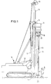
- a mobile excavator 10 is shown, the Equipment for the production of in-situ concrete piles.
- To this Equipment includes an auxiliary mast 11 that is attached to the excavator 10 With the help of a hydraulic cylinder 12 can be erected.
- On the main mast or leader 13 is attached to the auxiliary mast 11.
- On the leader 13, a carriage 14 is mounted longitudinally. On this slide is attacked by a cable 15, which has a upper pulley 16 at the top of the leader and over a lower pulley 17 runs at the lower end of the leader.
- the Cable 15 is reversible by (not shown) cable winches driven so that the carriage 14 move on the leader can be.
- the carriage 14 carries a vibrator 18, which contains rotating eccentric masses running in pairs, which generate vertical vibrations.
- the tube 21 is a cylindrical steel tube, which as a formwork element for the in-situ concrete pile to be manufactured serves.
- the tube has one at its upper end Flange for attachment to the head piece 20 while the lower end is flangeless.
- the tube 21 has in the Usually a length of several meters.
- the outside diameter of the Rohres is for example 40 or 60 cm or 75 cm.
- the lower end of the tube 21 is closed with a cover 22.
- the cover 22 consists of a flat disk 23 with a circumferential collar 24 which surrounds the pipe end.
- a sealing sheet 25 is inserted, the Disc 23 covered and stands up inside the collar 24.
- the Sealing membrane 25 consists of an elastic plastic seals the lower end of the tube 21 watertight.
- the geomembrane 25 is between the collar 24 of the lid and the Tube end clamped. It has such firmness that it at significant axial pressure of the tube is not punched out or is clarified. In the compressed state, it transmits the axial vibrational forces from tube 21 to cover 22.
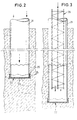
- FIG 2 is the shaking of the tube 21 in the ground shown.
- the lower tube end is with the cover 23 below Intermediate layer of the sealing membrane 25 closed. This will prevents water from entering the pipe.
- This driving force is greater than the weight forces acting on the tube 21 from the tube and vibrating device. It is at least twice this weight.
- the Vibrating device 18 has a weight of 6 to 9 t and the tube 21 a weight of 1 t.
- the additionally applied by the cable 15 vertical driving force is 16 to 20 t. Through the Propulsion force is achieved that the vibration vibrations be effectively converted into propulsive power.
- Figure 3 shows the tube 21 which is to the desired depth was brought down by shaking. Then the jogger 18 removed from the head piece 20 and an iron reinforcement 26 lowered into the tube 21.
- the vibrator 18 After filling the tube 21 with concrete 27, the vibrator 18 reattached to the head piece 20 with the jaws 19 and put it into operation.
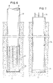
- the tube 21 is according to Figure 5 exposed to vertical vibrations. Here condensed the concrete, with an aqueous along the pipe wall Layer 28 forms.
- the lower tube end lifts off the lid, which is only loose was put on.
- the pipe 21 is pulled up under further actuation of the vibrating device 18.
- the retraction the tube is smooth and trouble-free due to the vibrating motion, so that there are no abrupt bumps. This is one consistently high quality of in-situ concrete ensured.
- FIG 7 shows the finished in-situ concrete pile 30 in the ground.
- the concrete pile is still on the cover 22, which is the geomembrane 25 contains. These parts form lost formwork parts.
Landscapes
- Engineering & Computer Science (AREA)
- Structural Engineering (AREA)
- Life Sciences & Earth Sciences (AREA)
- General Engineering & Computer Science (AREA)
- Paleontology (AREA)
- Civil Engineering (AREA)
- Mining & Mineral Resources (AREA)
- General Life Sciences & Earth Sciences (AREA)
- Agronomy & Crop Science (AREA)
- Environmental & Geological Engineering (AREA)
- Soil Sciences (AREA)
- Piles And Underground Anchors (AREA)
- Placing Or Removing Of Piles Or Sheet Piles, Or Accessories Thereof (AREA)
Abstract
Description
- Fig. 1
- eine Seitenansicht der Vorrichtung zur Herstellung von Ortbetonpfählen,
- Fig. 2
- einen Vertikalschnitt durch den Boden während des Niederbringens des mit einem Deckel verschlossenen Rohres,
- Fig. 3
- das Einsetzen einer Bewehrung in das Rohr,
- Fig. 4
- das Einfüllen von Beton in das Rohr,
- Fig. 5
- das Rütteln des Rohres zum Verdichten des Betons,
- Fig. 6
- das Ziehen des Rohres, und
- Fig. 7
- den fertigen Ortbetonpfahl.
Claims (6)
- Verfahren zur Herstellung eines Ortbetonpfahls (30) mit den SchrittenEinbringen eines Rohres (21), das am vorderen Ende mit einem vorgesetzten Deckel (22) abgeschlossen ist, in den Boden durch Betätigung einer auf das rückwärtige Rohrende aufgesetzten Rüttelvorrichtung (18),Einfüllen von Beton (27) in das Rohr (21),Verdichten des Betons durch Rütteln des Rohres (21),Zurückziehen des Rohres (21) unter Zurücklassung des Betons.
- Verfahren nach Anspruch 1, dadurch gekennzeichnet, dass während der Betätigung der Rüttelvorrichtung (18) eine stationäre Vortriebskraft (15) auf das Rohr (21) ausgeübt wird.
- Verfahren nach Anspruch 1 oder 2, dadurch gekennzeichnet, dass der Deckel (22) mit einem umlaufenden Kragen (24) unter Einschluß einer Dichtungsbahn (25) auf das vordere Rohrende aufgesetzt wird.
- Verfahren nach einem der Ansprüche 1-3, dadurch gekennzeichnet, dass das Verdichten des Betons (27) unter Einsatz derselben Rüttelvorrichtung (18) wie das Einbringen des Rohres (21) erfolgt.
- Vorrichtung zur Herstellung eines Ortbetonpfahls (30), mit einem langgestreckten Mäkler (13), einem längs des Mäklers (13) verfahrbaren Schlitten (14), der eine Rüttelvorrichtung (18) trägt, einem an der Rüttelvorrichtung (18) befestigten, den Vibrationen der Rüttelvorrichtung ausgesetzten Rohr (21), einem das vordere Ende des Rohres (21) verschließenden losen Deckel (22) und einem Seilzug (15) zum Aufbringen einer Vortriebskraft auf das Rohr (21) und zum Zurückziehen des Rohres.
- Vorrichtung nach Anspruch 5, dadurch gekennzeichnet, dass der Deckel (22) einen umlaufenden Kragen (24) hat und dass zwischen dem Rohr (21) und dem Deckel (22) eine elastische Dichtungsbahn (25) eingeklemmt ist.
Priority Applications (1)
| Application Number | Priority Date | Filing Date | Title |
|---|---|---|---|
| DE20121387U DE20121387U1 (de) | 2000-03-17 | 2001-03-16 | Vorrichtung zur Herstellung eines Ortbetonpfahles |
Applications Claiming Priority (2)
| Application Number | Priority Date | Filing Date | Title |
|---|---|---|---|
| DE10013446A DE10013446A1 (de) | 2000-03-17 | 2000-03-17 | Verfahren und Vorrichtung zur Herstellung eines Ortbetonpfahles |
| DE10013446 | 2000-03-17 |
Publications (3)
| Publication Number | Publication Date |
|---|---|
| EP1134319A2 true EP1134319A2 (de) | 2001-09-19 |
| EP1134319A3 EP1134319A3 (de) | 2002-08-21 |
| EP1134319B1 EP1134319B1 (de) | 2005-07-27 |
Family
ID=7635397
Family Applications (1)
| Application Number | Title | Priority Date | Filing Date |
|---|---|---|---|
| EP01106639A Expired - Lifetime EP1134319B1 (de) | 2000-03-17 | 2001-03-16 | Verfahren und Vorrichtung zur Herstellung eines Ortbetonpfahls |
Country Status (6)
| Country | Link |
|---|---|
| EP (1) | EP1134319B1 (de) |
| AT (1) | ATE300637T1 (de) |
| CY (1) | CY1105546T1 (de) |
| DE (2) | DE10013446A1 (de) |
| DK (1) | DK1134319T3 (de) |
| ES (1) | ES2246268T3 (de) |
Cited By (9)
| Publication number | Priority date | Publication date | Assignee | Title |
|---|---|---|---|---|
| EP1726719A1 (de) * | 2005-05-13 | 2006-11-29 | Liebherr-Werk Nenzing GmbH | Verfahren und Vorrichtung zur Herstellung eines Ortbeton-Vollverdrängerpfahles |
| DE10310727B4 (de) * | 2003-03-12 | 2007-09-13 | Bauer Spezialtiefbau Gmbh | Füllrohr |
| EP1884600A1 (de) * | 2006-07-24 | 2008-02-06 | Liebherr-Werk Nenzing GmbH | Vorrichtung zur Herstellung eines Ortbeton-Vollverdrängerpfahles |
| EP1983112A1 (de) * | 2007-04-16 | 2008-10-22 | IHC Holland IE B.V. | Vibrationsrüttler zum Niederbringen eines Pfahls oder eines Formrohres |
| CN102444121A (zh) * | 2011-10-24 | 2012-05-09 | 河南理工大学 | 一种五星形现浇混凝土桩施工方法 |
| NL2021375B1 (en) * | 2018-07-23 | 2020-01-30 | Ihc Holland Ie Bv | Pile installation system |
| IT201900012816A1 (it) | 2019-07-24 | 2021-01-24 | Geosec S R L | Dispositivo semovente per infissione di pali nel terreno |
| CN113202087A (zh) * | 2021-06-11 | 2021-08-03 | 陈清贵 | 一种气压推挤和振动装置 |
| CN113338271A (zh) * | 2021-05-12 | 2021-09-03 | 西安理工大学 | 一种混凝土空心桩浇筑方法及浇筑装置 |
Families Citing this family (5)
| Publication number | Priority date | Publication date | Assignee | Title |
|---|---|---|---|---|
| DE10219862B4 (de) * | 2002-05-03 | 2005-07-14 | Bauer Spezialtiefbau Gmbh | Verfahren und Tiefbauvorrichtung zur Herstellung einer Gründungssäule in einem Boden |
| DE102004045799B3 (de) * | 2004-09-22 | 2006-03-30 | Josef Möbius Bau-Aktiengesellschaft | Verfahren und Anlage zur Herstellung von Betonsäulen kleineren Durchmessers im Boden |
| DE102015122202B4 (de) * | 2015-10-22 | 2019-03-28 | Peter Wallis | Vorrichtung zum Einbringen eines Säulenelements |
| DE102019108100B3 (de) * | 2019-03-28 | 2020-03-26 | Jannes Janitschke | Pfahlgründungsbohrgerät |
| CN116397657A (zh) * | 2023-05-18 | 2023-07-07 | 中建八局第三建设有限公司 | 一种一柱一桩接头处混凝土泛浆抑制方法 |
Family Cites Families (8)
| Publication number | Priority date | Publication date | Assignee | Title |
|---|---|---|---|---|
| US1865652A (en) * | 1929-09-20 | 1932-07-05 | Raymond Concrete Pile Co | Method and apparatus for placing concrete in piles |
| DE2619431A1 (de) * | 1976-05-03 | 1977-11-24 | Mann Gmbh & Co Fritz | Verfahren zum herstellen eines ortbetonpfahles |
| GB1594452A (en) * | 1976-10-27 | 1981-07-30 | Bsp Int Foundation | Impact apparatus |
| CH648074A5 (en) * | 1980-07-02 | 1985-02-28 | Fietz & Leuthold Ag | Method of constructing a cast-in-place pile |
| DE3612437A1 (de) * | 1986-04-12 | 1987-10-15 | Preussag Ag Bauwesen | Verfahren zur herstellung von betonsaeulen im boden und vorrichtung zur durchfuehrung des verfahrens |
| DE9409581U1 (de) * | 1994-06-15 | 1995-07-20 | Fa. Josef Messmann, 26871 Papenburg | Vorrichtung zum Rammen, insbesondere von Spundwänden, mit einem Vibrator |
| DE19532931A1 (de) * | 1995-09-06 | 1997-03-13 | Karl Rainer Massarsch | Verfahren zum Ausbilden von Fundamenten |
| DE19707687C1 (de) * | 1997-02-26 | 1998-10-15 | Wilhelm Dr Degen | Vorrichtung zum Herstellen von Materialsäulen im Boden |
-
2000
- 2000-03-17 DE DE10013446A patent/DE10013446A1/de not_active Withdrawn
-
2001
- 2001-03-16 AT AT01106639T patent/ATE300637T1/de active
- 2001-03-16 DK DK01106639T patent/DK1134319T3/da active
- 2001-03-16 DE DE50106844T patent/DE50106844D1/de not_active Expired - Lifetime
- 2001-03-16 ES ES01106639T patent/ES2246268T3/es not_active Expired - Lifetime
- 2001-03-16 EP EP01106639A patent/EP1134319B1/de not_active Expired - Lifetime
-
2005
- 2005-10-26 CY CY20051101301T patent/CY1105546T1/el unknown
Non-Patent Citations (1)
| Title |
|---|
| BUJA H-O.: "Handbuch des Spezialtiefbaus", 1998, WERNER VERLAG GMBH, GERMANY, ISBN: 3-8041-4233-8, pages: 207 - 210, XP002990651 |
Cited By (11)
| Publication number | Priority date | Publication date | Assignee | Title |
|---|---|---|---|---|
| DE10310727B4 (de) * | 2003-03-12 | 2007-09-13 | Bauer Spezialtiefbau Gmbh | Füllrohr |
| EP1726719A1 (de) * | 2005-05-13 | 2006-11-29 | Liebherr-Werk Nenzing GmbH | Verfahren und Vorrichtung zur Herstellung eines Ortbeton-Vollverdrängerpfahles |
| EP1884600A1 (de) * | 2006-07-24 | 2008-02-06 | Liebherr-Werk Nenzing GmbH | Vorrichtung zur Herstellung eines Ortbeton-Vollverdrängerpfahles |
| EP1983112A1 (de) * | 2007-04-16 | 2008-10-22 | IHC Holland IE B.V. | Vibrationsrüttler zum Niederbringen eines Pfahls oder eines Formrohres |
| CN102444121A (zh) * | 2011-10-24 | 2012-05-09 | 河南理工大学 | 一种五星形现浇混凝土桩施工方法 |
| NL2021375B1 (en) * | 2018-07-23 | 2020-01-30 | Ihc Holland Ie Bv | Pile installation system |
| WO2020022882A1 (en) * | 2018-07-23 | 2020-01-30 | Ihc Holland Ie B.V. | Pile installation system |
| US11725356B2 (en) | 2018-07-23 | 2023-08-15 | Fundex Equipment B.V. | Pile installation system |
| IT201900012816A1 (it) | 2019-07-24 | 2021-01-24 | Geosec S R L | Dispositivo semovente per infissione di pali nel terreno |
| CN113338271A (zh) * | 2021-05-12 | 2021-09-03 | 西安理工大学 | 一种混凝土空心桩浇筑方法及浇筑装置 |
| CN113202087A (zh) * | 2021-06-11 | 2021-08-03 | 陈清贵 | 一种气压推挤和振动装置 |
Also Published As
| Publication number | Publication date |
|---|---|
| EP1134319B1 (de) | 2005-07-27 |
| DE10013446A1 (de) | 2002-01-24 |
| ATE300637T1 (de) | 2005-08-15 |
| DK1134319T3 (da) | 2005-11-28 |
| ES2246268T3 (es) | 2006-02-16 |
| EP1134319A3 (de) | 2002-08-21 |
| DE50106844D1 (de) | 2005-09-01 |
| CY1105546T1 (el) | 2010-07-28 |
Similar Documents
| Publication | Publication Date | Title |
|---|---|---|
| DE69823223T2 (de) | Verfahren für bohrungen und gründungspfählen | |
| DE102012223992B3 (de) | Vorrichtung und Verfahren zur Bodenverdichtung und/oder Bodenverfestigung | |
| EP1134319B1 (de) | Verfahren und Vorrichtung zur Herstellung eines Ortbetonpfahls | |
| DE3445965A1 (de) | Verdichtende tiefgruendung, verfahren und vorrichtung zu deren herstellen | |
| DE4408173C2 (de) | Verfahren zur Stabilisierung des Untergrundes und zur Abtragung von Bauwerks- und Verkehrslasten | |
| DE19941302C2 (de) | Vorrichtung und Verfahren zur Herstellung von im Boden versenkten Tragsäulen | |
| EP2925934B1 (de) | Verfahren zur herstellung eines pfahls | |
| DE69406925T2 (de) | Konstruktionsverfahren eines gruendungpfahles unter verwendung einer vorgefertigten pfahlhuelse | |
| DE10025966C2 (de) | Stützschlauch-Säulen | |
| DE4303518C2 (de) | Verfahren und Vorrichtung zum Verfestigen einer Deponie von vorverdichtetem Altmüll unter Erschließung von zusätzlicher Aufnahmekapazität für Frischmüll | |
| DE20121387U1 (de) | Vorrichtung zur Herstellung eines Ortbetonpfahles | |
| DE2948879C2 (de) | Verfahren zum Herstellen von Ortbeton-Rammpfählen | |
| DE19509088A1 (de) | Verfahren zur Herstellung eines Ortbetonrammpfahles und Einrichtung zur Durchführung des Verfahrens | |
| DE19608815C1 (de) | Vorrichtung und Verfahren zur Herstellung einer Dichtsohle im Boden | |
| DE102005008679A1 (de) | Verfahren zur Herstellung von Rammpfählen mit mindestens einem doppelwandigen Rammrohr | |
| DE102021116487B3 (de) | Geotextilummantelte Flüssigbodensäulen | |
| DE2335378A1 (de) | Verfahren und vorrichtung zum abteufen von schachtbauwerken | |
| DE102010024607A1 (de) | Gründungspfahl sowie Verfahren zu seiner Herstellung | |
| DE609238C (de) | Verfahren zur Herstellung einer ausreichend wasserdichten Baugrubenumschliessung innerhalb des die Grube umgebenden Bodens | |
| DE102013226121B4 (de) | Vorrichtung und Verfahren zur Bodenverdichtung und/oder Bodenverfestigung | |
| DE2619431A1 (de) | Verfahren zum herstellen eines ortbetonpfahles | |
| WO1999013167A1 (de) | Verfahren zur gründung mit pfählen | |
| DE10218330A1 (de) | Verfahren und Vorrichtung zur Herstellung von Materialsäulen im Boden | |
| DE10007707A1 (de) | Verfahren und Vorrichtung für die Verdichtung von bindigem u. nichtbindigem Gut durch pulsende Verdrängung | |
| DE2521712A1 (de) | Verfahren zur fertigung von ortpfaehlen mit verbreiterungen im unteren teil |
Legal Events
| Date | Code | Title | Description |
|---|---|---|---|
| PUAI | Public reference made under article 153(3) epc to a published international application that has entered the european phase |
Free format text: ORIGINAL CODE: 0009012 |
|
| AK | Designated contracting states |
Kind code of ref document: A2 Designated state(s): AT BE CH CY DE DK ES FI FR GB GR IE IT LI LU MC NL PT SE TR |
|
| AX | Request for extension of the european patent |
Free format text: AL;LT;LV;MK;RO;SI |
|
| PUAL | Search report despatched |
Free format text: ORIGINAL CODE: 0009013 |
|
| AK | Designated contracting states |
Kind code of ref document: A3 Designated state(s): AT BE CH CY DE DK ES FI FR GB GR IE IT LI LU MC NL PT SE TR |
|
| AX | Request for extension of the european patent |
Free format text: AL;LT;LV;MK;RO;SI |
|
| RIC1 | Information provided on ipc code assigned before grant |
Free format text: 7E 02D 5/38 A, 7E 02D 7/18 B, 7E 02D 5/46 B, 7E 02D 5/30 B, 7E 02D 5/44 B, 7E 02D 5/70 B, 7E 02D 3/10 B |
|
| 17P | Request for examination filed |
Effective date: 20030213 |
|
| 17Q | First examination report despatched |
Effective date: 20030313 |
|
| AKX | Designation fees paid |
Designated state(s): AT BE CH CY DE DK ES FI FR GB GR IE IT LI LU MC NL PT SE TR |
|
| AXX | Extension fees paid |
Extension state: LT Payment date: 20030213 Extension state: LV Payment date: 20030213 |
|
| GRAP | Despatch of communication of intention to grant a patent |
Free format text: ORIGINAL CODE: EPIDOSNIGR1 |
|
| TPAC | Observations filed by third parties |
Free format text: ORIGINAL CODE: EPIDOSNTIPA |
|
| GRAP | Despatch of communication of intention to grant a patent |
Free format text: ORIGINAL CODE: EPIDOSNIGR1 |
|
| GRAS | Grant fee paid |
Free format text: ORIGINAL CODE: EPIDOSNIGR3 |
|
| GRAA | (expected) grant |
Free format text: ORIGINAL CODE: 0009210 |
|
| AK | Designated contracting states |
Kind code of ref document: B1 Designated state(s): AT BE CH CY DE DK ES FI FR GB GR IE IT LI LU MC NL PT SE TR |
|
| AX | Request for extension of the european patent |
Extension state: LT LV |
|
| REG | Reference to a national code |
Ref country code: GB Ref legal event code: FG4D Free format text: NOT ENGLISH |
|
| REG | Reference to a national code |
Ref country code: CH Ref legal event code: EP |
|
| REG | Reference to a national code |
Ref country code: IE Ref legal event code: FG4D Free format text: LANGUAGE OF EP DOCUMENT: GERMAN |
|
| REF | Corresponds to: |
Ref document number: 50106844 Country of ref document: DE Date of ref document: 20050901 Kind code of ref document: P |
|
| REG | Reference to a national code |
Ref country code: CH Ref legal event code: NV Representative=s name: ISLER & PEDRAZZINI AG |
|
| REG | Reference to a national code |
Ref country code: SE Ref legal event code: TRGR |
|
| GBT | Gb: translation of ep patent filed (gb section 77(6)(a)/1977) |
Effective date: 20051007 |
|
| REG | Reference to a national code |
Ref country code: DK Ref legal event code: T3 |
|
| REG | Reference to a national code |
Ref country code: GR Ref legal event code: EP Ref document number: 20050403137 Country of ref document: GR |
|
| REG | Reference to a national code |
Ref country code: ES Ref legal event code: FG2A Ref document number: 2246268 Country of ref document: ES Kind code of ref document: T3 |
|
| PG25 | Lapsed in a contracting state [announced via postgrant information from national office to epo] |
Ref country code: MC Free format text: LAPSE BECAUSE OF NON-PAYMENT OF DUE FEES Effective date: 20060331 |
|
| ET | Fr: translation filed | ||
| PLBE | No opposition filed within time limit |
Free format text: ORIGINAL CODE: 0009261 |
|
| STAA | Information on the status of an ep patent application or granted ep patent |
Free format text: STATUS: NO OPPOSITION FILED WITHIN TIME LIMIT |
|
| 26N | No opposition filed |
Effective date: 20060428 |
|
| PGFP | Annual fee paid to national office [announced via postgrant information from national office to epo] |
Ref country code: PT Payment date: 20070307 Year of fee payment: 7 |
|
| PGFP | Annual fee paid to national office [announced via postgrant information from national office to epo] |
Ref country code: CY Payment date: 20070308 Year of fee payment: 7 |
|
| PGFP | Annual fee paid to national office [announced via postgrant information from national office to epo] |
Ref country code: IE Payment date: 20070323 Year of fee payment: 7 Ref country code: BE Payment date: 20070323 Year of fee payment: 7 |
|
| PGFP | Annual fee paid to national office [announced via postgrant information from national office to epo] |
Ref country code: DK Payment date: 20070326 Year of fee payment: 7 Ref country code: SE Payment date: 20070326 Year of fee payment: 7 Ref country code: LU Payment date: 20070326 Year of fee payment: 7 |
|
| PGFP | Annual fee paid to national office [announced via postgrant information from national office to epo] |
Ref country code: FI Payment date: 20070327 Year of fee payment: 7 |
|
| REG | Reference to a national code |
Ref country code: CH Ref legal event code: PCAR Free format text: ISLER & PEDRAZZINI AG;POSTFACH 1772;8027 ZUERICH (CH) |
|
| PGFP | Annual fee paid to national office [announced via postgrant information from national office to epo] |
Ref country code: TR Payment date: 20070307 Year of fee payment: 7 |
|
| PGFP | Annual fee paid to national office [announced via postgrant information from national office to epo] |
Ref country code: GR Payment date: 20070323 Year of fee payment: 7 |
|
| REG | Reference to a national code |
Ref country code: FR Ref legal event code: TP |
|
| REG | Reference to a national code |
Ref country code: CH Ref legal event code: NV Representative=s name: BOVARD AG PATENTANWAELTE Ref country code: CH Ref legal event code: PUE Owner name: LIEBHERR-WERK NENZING GMBH Free format text: BVV SPEZIALTIEFBAUTECHNIK VERTRIEBS GMBH#BLEIBTREUSTRASSE 9#81479 MUENCHEN (DE) -TRANSFER TO- LIEBHERR-WERK NENZING GMBH#DR. - HANS-LIEBHERR-STRASSE 1#6710 NENZING (AT) |
|
| NLS | Nl: assignments of ep-patents |
Owner name: LIEBHERR-WERK NENZING GMBH Effective date: 20080522 |
|
| REG | Reference to a national code |
Ref country code: GB Ref legal event code: 732E |
|
| BERE | Be: lapsed |
Owner name: *BVV SPEZIALTIEFBAUTECHNIK VERTRIEBS G.M.B.H. Effective date: 20080331 |
|
| REG | Reference to a national code |
Ref country code: PT Ref legal event code: MM4A Free format text: LAPSE DUE TO NON-PAYMENT OF FEES Effective date: 20080916 |
|
| PG25 | Lapsed in a contracting state [announced via postgrant information from national office to epo] |
Ref country code: FI Free format text: LAPSE BECAUSE OF NON-PAYMENT OF DUE FEES Effective date: 20080316 Ref country code: PT Free format text: LAPSE BECAUSE OF NON-PAYMENT OF DUE FEES Effective date: 20080916 |
|
| REG | Reference to a national code |
Ref country code: DK Ref legal event code: EBP |
|
| EUG | Se: european patent has lapsed | ||
| PG25 | Lapsed in a contracting state [announced via postgrant information from national office to epo] |
Ref country code: CY Free format text: LAPSE BECAUSE OF NON-PAYMENT OF DUE FEES Effective date: 20080316 |
|
| REG | Reference to a national code |
Ref country code: IE Ref legal event code: MM4A |
|
| PG25 | Lapsed in a contracting state [announced via postgrant information from national office to epo] |
Ref country code: SE Free format text: LAPSE BECAUSE OF NON-PAYMENT OF DUE FEES Effective date: 20080317 Ref country code: IE Free format text: LAPSE BECAUSE OF NON-PAYMENT OF DUE FEES Effective date: 20080317 |
|
| PG25 | Lapsed in a contracting state [announced via postgrant information from national office to epo] |
Ref country code: BE Free format text: LAPSE BECAUSE OF NON-PAYMENT OF DUE FEES Effective date: 20080331 |
|
| PG25 | Lapsed in a contracting state [announced via postgrant information from national office to epo] |
Ref country code: DK Free format text: LAPSE BECAUSE OF NON-PAYMENT OF DUE FEES Effective date: 20080331 |
|
| PG25 | Lapsed in a contracting state [announced via postgrant information from national office to epo] |
Ref country code: GR Free format text: LAPSE BECAUSE OF NON-PAYMENT OF DUE FEES Effective date: 20081002 |
|
| PG25 | Lapsed in a contracting state [announced via postgrant information from national office to epo] |
Ref country code: LU Free format text: LAPSE BECAUSE OF NON-PAYMENT OF DUE FEES Effective date: 20080316 |
|
| REG | Reference to a national code |
Ref country code: CH Ref legal event code: PFA Owner name: LIEBHERR-WERK NENZING GMBH Free format text: LIEBHERR-WERK NENZING GMBH#DR. - HANS-LIEBHERR-STRASSE 1#6710 NENZING (AT) -TRANSFER TO- LIEBHERR-WERK NENZING GMBH#DR. - HANS-LIEBHERR-STRASSE 1#6710 NENZING (AT) |
|
| PG25 | Lapsed in a contracting state [announced via postgrant information from national office to epo] |
Ref country code: TR Free format text: LAPSE BECAUSE OF NON-PAYMENT OF DUE FEES Effective date: 20100923 |
|
| PG25 | Lapsed in a contracting state [announced via postgrant information from national office to epo] |
Ref country code: TR Free format text: LAPSE BECAUSE OF NON-PAYMENT OF DUE FEES Effective date: 20080316 |
|
| PGFP | Annual fee paid to national office [announced via postgrant information from national office to epo] |
Ref country code: ES Payment date: 20140307 Year of fee payment: 14 Ref country code: IT Payment date: 20140324 Year of fee payment: 14 |
|
| PGFP | Annual fee paid to national office [announced via postgrant information from national office to epo] |
Ref country code: GB Payment date: 20140320 Year of fee payment: 14 |
|
| PGFP | Annual fee paid to national office [announced via postgrant information from national office to epo] |
Ref country code: FR Payment date: 20140410 Year of fee payment: 14 |
|
| PGFP | Annual fee paid to national office [announced via postgrant information from national office to epo] |
Ref country code: CH Payment date: 20150319 Year of fee payment: 15 Ref country code: NL Payment date: 20150319 Year of fee payment: 15 |
|
| PGFP | Annual fee paid to national office [announced via postgrant information from national office to epo] |
Ref country code: AT Payment date: 20150323 Year of fee payment: 15 |
|
| PGFP | Annual fee paid to national office [announced via postgrant information from national office to epo] |
Ref country code: DE Payment date: 20150330 Year of fee payment: 15 |
|
| GBPC | Gb: european patent ceased through non-payment of renewal fee |
Effective date: 20150316 |
|
| PG25 | Lapsed in a contracting state [announced via postgrant information from national office to epo] |
Ref country code: IT Free format text: LAPSE BECAUSE OF NON-PAYMENT OF DUE FEES Effective date: 20150316 |
|
| REG | Reference to a national code |
Ref country code: FR Ref legal event code: ST Effective date: 20151130 |
|
| PG25 | Lapsed in a contracting state [announced via postgrant information from national office to epo] |
Ref country code: GB Free format text: LAPSE BECAUSE OF NON-PAYMENT OF DUE FEES Effective date: 20150316 |
|
| PG25 | Lapsed in a contracting state [announced via postgrant information from national office to epo] |
Ref country code: FR Free format text: LAPSE BECAUSE OF NON-PAYMENT OF DUE FEES Effective date: 20150331 |
|
| REG | Reference to a national code |
Ref country code: ES Ref legal event code: FD2A Effective date: 20160426 |
|
| PG25 | Lapsed in a contracting state [announced via postgrant information from national office to epo] |
Ref country code: ES Free format text: LAPSE BECAUSE OF NON-PAYMENT OF DUE FEES Effective date: 20150317 |
|
| REG | Reference to a national code |
Ref country code: DE Ref legal event code: R119 Ref document number: 50106844 Country of ref document: DE |
|
| REG | Reference to a national code |
Ref country code: CH Ref legal event code: PL |
|
| REG | Reference to a national code |
Ref country code: AT Ref legal event code: MM01 Ref document number: 300637 Country of ref document: AT Kind code of ref document: T Effective date: 20160316 |
|
| REG | Reference to a national code |
Ref country code: NL Ref legal event code: MM Effective date: 20160401 |
|
| PG25 | Lapsed in a contracting state [announced via postgrant information from national office to epo] |
Ref country code: DE Free format text: LAPSE BECAUSE OF NON-PAYMENT OF DUE FEES Effective date: 20161001 Ref country code: LI Free format text: LAPSE BECAUSE OF NON-PAYMENT OF DUE FEES Effective date: 20160331 Ref country code: CH Free format text: LAPSE BECAUSE OF NON-PAYMENT OF DUE FEES Effective date: 20160331 Ref country code: NL Free format text: LAPSE BECAUSE OF NON-PAYMENT OF DUE FEES Effective date: 20160401 |
|
| PG25 | Lapsed in a contracting state [announced via postgrant information from national office to epo] |
Ref country code: AT Free format text: LAPSE BECAUSE OF NON-PAYMENT OF DUE FEES Effective date: 20160316 |