EP1132992B1 - Detektor zum Messen der Dosisleistung von Röntgenstrahlen sowie Vorrichtung zum Sortieren von Altbatterien und/oder Altakkumulatoren nach ihrem Typ - Google Patents
Detektor zum Messen der Dosisleistung von Röntgenstrahlen sowie Vorrichtung zum Sortieren von Altbatterien und/oder Altakkumulatoren nach ihrem Typ Download PDFInfo
- Publication number
- EP1132992B1 EP1132992B1 EP20010105714 EP01105714A EP1132992B1 EP 1132992 B1 EP1132992 B1 EP 1132992B1 EP 20010105714 EP20010105714 EP 20010105714 EP 01105714 A EP01105714 A EP 01105714A EP 1132992 B1 EP1132992 B1 EP 1132992B1
- Authority
- EP
- European Patent Office
- Prior art keywords
- accumulators
- station
- cells
- ray
- detector
- Prior art date
- Legal status (The legal status is an assumption and is not a legal conclusion. Google has not performed a legal analysis and makes no representation as to the accuracy of the status listed.)
- Expired - Lifetime
Links
Images



Classifications
-
- H—ELECTRICITY
- H01—ELECTRIC ELEMENTS
- H01M—PROCESSES OR MEANS, e.g. BATTERIES, FOR THE DIRECT CONVERSION OF CHEMICAL ENERGY INTO ELECTRICAL ENERGY
- H01M10/00—Secondary cells; Manufacture thereof
- H01M10/54—Reclaiming serviceable parts of waste accumulators
-
- B—PERFORMING OPERATIONS; TRANSPORTING
- B07—SEPARATING SOLIDS FROM SOLIDS; SORTING
- B07C—POSTAL SORTING; SORTING INDIVIDUAL ARTICLES, OR BULK MATERIAL FIT TO BE SORTED PIECE-MEAL, e.g. BY PICKING
- B07C5/00—Sorting according to a characteristic or feature of the articles or material being sorted, e.g. by control effected by devices which detect or measure such characteristic or feature; Sorting by manually actuated devices, e.g. switches
- B07C5/34—Sorting according to other particular properties
- B07C5/3416—Sorting according to other particular properties according to radiation transmissivity, e.g. for light, x-rays, particle radiation
-
- B—PERFORMING OPERATIONS; TRANSPORTING
- B07—SEPARATING SOLIDS FROM SOLIDS; SORTING
- B07C—POSTAL SORTING; SORTING INDIVIDUAL ARTICLES, OR BULK MATERIAL FIT TO BE SORTED PIECE-MEAL, e.g. BY PICKING
- B07C5/00—Sorting according to a characteristic or feature of the articles or material being sorted, e.g. by control effected by devices which detect or measure such characteristic or feature; Sorting by manually actuated devices, e.g. switches
- B07C5/34—Sorting according to other particular properties
- B07C5/346—Sorting according to other particular properties according to radioactive properties
-
- H—ELECTRICITY
- H01—ELECTRIC ELEMENTS
- H01M—PROCESSES OR MEANS, e.g. BATTERIES, FOR THE DIRECT CONVERSION OF CHEMICAL ENERGY INTO ELECTRICAL ENERGY
- H01M6/00—Primary cells; Manufacture thereof
- H01M6/52—Reclaiming serviceable parts of waste cells or batteries, e.g. recycling
-
- B—PERFORMING OPERATIONS; TRANSPORTING
- B07—SEPARATING SOLIDS FROM SOLIDS; SORTING
- B07C—POSTAL SORTING; SORTING INDIVIDUAL ARTICLES, OR BULK MATERIAL FIT TO BE SORTED PIECE-MEAL, e.g. BY PICKING
- B07C2501/00—Sorting according to a characteristic or feature of the articles or material to be sorted
- B07C2501/0036—Sorting out metallic particles
-
- Y—GENERAL TAGGING OF NEW TECHNOLOGICAL DEVELOPMENTS; GENERAL TAGGING OF CROSS-SECTIONAL TECHNOLOGIES SPANNING OVER SEVERAL SECTIONS OF THE IPC; TECHNICAL SUBJECTS COVERED BY FORMER USPC CROSS-REFERENCE ART COLLECTIONS [XRACs] AND DIGESTS
- Y02—TECHNOLOGIES OR APPLICATIONS FOR MITIGATION OR ADAPTATION AGAINST CLIMATE CHANGE
- Y02W—CLIMATE CHANGE MITIGATION TECHNOLOGIES RELATED TO WASTEWATER TREATMENT OR WASTE MANAGEMENT
- Y02W30/00—Technologies for solid waste management
- Y02W30/50—Reuse, recycling or recovery technologies
- Y02W30/84—Recycling of batteries or fuel cells
Definitions
- the invention relates to a device for sorting used batteries and / or accumulators (cells) according to their type with a recognition station for scanning the old batteries and / or Altakkumulatoren with X-rays, with a detector for measuring the dose rate and with a subsequent sorting station for sorting the waste batteries and / or accumulators according to their type on the basis of the dose rate measured by the detector.
- the batteries and accumulators available today on the market contain, depending on their electrochemical cell type, in various concentrations particularly toxic heavy metals, such as mercury, cadmium or lead.
- toxic heavy metals such as mercury, cadmium or lead.
- they are now collected in most industrialized countries, partly by being withdrawn through trade.
- trade collection containers are set up for this, in which the public can throw in his used batteries and Altakkumulatoren.
- Some batteries and accumulators contain high-priced metals, such as silver, nickel, cadmium or zinc, in concentrations substantially above the degradable levels in the corresponding natural ores. It therefore makes sense to use these types of batteries metallurgically.
- the old batteries and accumulators inserted into the collection containers must therefore be sorted according to their type, that is, depending on their electrochemical cell type. Currently, this sorting is still done manually, with maximum grade purity levels well below 80%. Only by an automatic sorting are the purity levels of more than 99% required for metallurgical recycling possible.
- the waste batteries and accumulators according to DE 196 10 093 A1 are recognized in their X-ray fluoroscopic image or in the total transmission of the X-ray radiation in a transillumination arrangement and sorted accordingly.
- the batteries are detected by measuring the weight, the format, the ferromagnetic properties and the eddy current characteristic when passing through a coil (WO 94/19838, DE 692 03 091 T2, EP 0 580 241 A2).
- the cells are identified by conventional image processing via a label ("Proceedings of the 4 th International Battery Recycling Congress", Hamburg, Germany, 1-3 July, 1998).
- Decisive for the profitability of an automatic battery sorting system is the maximum achievable sorting speed in addition to the purity of the sort.
- the total X-ray transmission of a single supplied battery in an X-ray fluoroscopy arrangement is measured by means of a sensor and included Reference data compared.
- a minimum belt speed of 1.5 m / sec must exist between the batteries for a typical battery length of 50 mm and a distance of about 10 cm required for a sorting station. be provided. This results in a maximum measuring time per battery of a maximum of 30 ms.
- the previously known X-ray dose rate meters such as counter tubes, ionization chambers, scintillation counters or semiconductor detectors, are not able to measure dose rates in this extremely short measurement time with a maximum allowable relevant error of less than 0.1%, based on the dose rate without object in the beam path , Furthermore, with this extremely short measuring time, it is necessary to work with very high dose rates of 10 to 10 4 Gy / h (air). In a fluoroscopy arrangement, the problem arises at these high dose rates that the sensor is exposed unprotected to the primary radiation between the individual batteries during the sequential supply of the batteries. Conventional detectors are quickly destroyed here.
- a method and apparatus for monitoring the thickness of a core of an electrical cable is known in which a detector is used with a phototransistor and an X-ray screen interconnected by an optical fiber.
- the invention is based on the problem to provide an apparatus for sorting waste batteries or accumulators according to their type, can be safely and economically detected and sorted by the old batteries or accumulators, depending on their electrochemical cell type, even over a longer period of operation.
- a detector for such a device is to be created, which can withstand unprotected high dose rates over a long period of operation without being destroyed.
- the device according to the invention is characterized in that the detector for measuring the dose rate of X-radiation for high dose rates up to 10 4 Gy / h, an X-ray screen and a phototransistor, which are interconnected by a plastic optical fiber.
- the X-radiation impinges on the X-ray screen, which is thereby excited to shine.
- the light emanating from the luminescent screen is passed through the plastic optical fiber to the phototransistor, which measures the brightness of the light emanating from the X-ray luminescent screen.
- the brightness of the light emanating from the X-ray screen is, within certain limits, proportional to the dose rate at the X-ray screen.
- a plastic optical fiber is to be provided, since a glass optical fiber would become very brown and therefore unusable.
- This detector is suitable for measuring X-ray radiation with a dose rate of up to 10 4 Gy / h in less than 30 ms with an accuracy of less than or equal to 0.2%, in particular 0.1%.
- the detector according to the invention can be advantageously used.
- the light guide preferably has a diameter of 1 mm. Since the optical waveguide attenuates the light emitted by the X-ray luminescent screen analogously to an electrical resistance over its length, ie attenuates it, it is expedient to provide a light guide of at least 1 m in length, in particular 10 m in length, in order to protect the phototransistor. A single-core optical fiber is sufficient to produce an effective detector.
- the size of the old battery or of the old accumulator serves as additional information. This can be determined, for example, by an upstream sieving of the battery / accumulator mixture. According to a development of the invention, however, it is provided to arrange at least two detectors or X-ray screens one above the other. Depending on how many detectors, counted from bottom to top, the measured dose rate changes when passing a battery or a Altakkumulators through the beam path, there is an additional information on the size of the battery under investigation.
- a conveyor, with which the waste batteries or accumulators are promoted by the recognition station, is also formed in a special way.
- the conveyor has a transport surface, which is inclined transversely to the transport direction relative to the horizontal.
- a lateral guide is provided in order to prevent a lateral fall of the old batteries or accumulators.
- the friction of the old batteries or accumulators Altakkumulatoren on the guide they will always align so that they point with their longitudinal axis in the transport direction.
- the spent batteries and accumulators are always promoted in exactly defined orientation by the recognition station.
- this measure can not ensure that the batteries are always promoted either with its plus or minus pole forward through the recognition station. But this is irrelevant for the present sorting problem.
- Another special feature of the invention is the sorting station. It is known from US Pat. No. 4,848,590 to allow articles to slide down a ramp. Due to signals from an upstream detection station, the articles are blown away from the ramp into different channels at different positions during the slipping down on the ramp by appropriate compressed air nozzles and, sorted according to their type, placed side by side on a conveyor belt.
- the problem here is that, in particular up to the lowest compressed air nozzle on the ramp a considerable transport path is covered, on which too much interference can occur, which in turn can lead to bad pitching and therefore poor sorting results.
- the recognition station directly adjoins the sorting station. This will the transport path between recognition station and sorting station is reduced to a minimum, so that any disturbances on this transport path does not occur and can lead to mistakes in the subsequent sorting of waste batteries and accumulators. It is sufficient if the distance between the recognition station and the sorting station (measured from the output of the recognition station to the entrance of the sorting station) corresponds at most twice the distance between two consecutive old batteries or accumulators in the area of the recognition station. Preferably, at most the simple distance of two successive waste batteries or accumulators in the area of the recognition station is provided.
- the spent batteries or accumulators are dropped at the entrance of the sorting station by a conveyor and deflected to sort of their ballistic trajectory, depending on the type, in different directions. Different types of spent batteries and accumulators are thus deflected from their ballistic trajectory at about the same location, depending on the type.
- the SortierGHzddling takes place for each type at about the same place, close behind the recognition station, so that disturbing influences can be largely excluded.
- Altakkumulatoren of their ballistic trajectory compressed air blasts are preferably used for deflecting the waste batteries and accumulators.
- a mixture of used batteries and accumulators with different electrochemical cell type hereinafter referred to as cell 10 for short, is deposited via a metering device 11 one after the other on a conveyor, namely a conveyor belt 12.
- a metering device 11 By the conveyor belt 12, the cells 10 on a second conveyor, here again a conveyor belt 13, stored.
- the conveyor belt 13 runs faster than the conveyor belt 12, so that the cells 10 are spatially equalized, so the distance between successive cells 10 is increased.
- the conveyor belt 13 has a relative to the horizontal transversely to the transport direction inclined transport surface. In the illustration of FIG. 3, the transport surface drops to the bottom right.
- a lateral guide 14 is provided in order to prevent lateral falling of the cells 10.
- the batteries are defined in a row and are thus fed to a detection station 15 sequentially in a defined orientation, namely with its longitudinal axis in the transport direction.
- the individual cells can be fed 10 times with their positive pole, sometimes with their negative pole to the front of the detection station 15. This is irrelevant for the detection of the electrochemical cell type.
- electrochemical cell type in the detection station 15 is greatly facilitated if the direction of the longitudinal axis of the cell 10 with respect to the transport direction is predetermined. In the present case, an alignment of the longitudinal axis of the cell 10 in the transport direction was selected.
- an X-ray source 16 in this case an X-ray tube, and on the X-ray source 16 opposite side of the conveyor belt 13, a detector 17 is provided.
- X-ray source 16 and detector 17 are arranged in the present case so that the cells 10 are irradiated with approximately perpendicular to the longitudinal axis of the cells 10 directed X-rays.
- the detector 17 measures the impinging dose rate, that is to say the total transmission of the X-ray radiation through the cell 10 to be determined. Since, due to the very short time available for determining the electrochemical cell type of the cell 10 to be examined, namely a maximum of 30 ms, must be worked with very high-energy X-ray radiation from the X-ray source 16. Conventional dose rate meters do not withstand the high dose rate of up to 10 4 Gy / h (eg 160 keV) required here.
- the detector 17 is therefore formed in a particular manner shown in more detail in FIG.
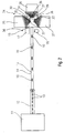
- the detector 17 has an X-ray phosphor screen 18. The X-ray radiation impinging on the X-ray luminescent screen 18 causes it to be illuminated.
- the brightness of the x-ray phosphor screen 18 irradiated with x-radiation is, within wide limits, proportional to the dose rate.
- the X-ray lighthouse 18 is in contact with a plastic light guide 19.
- the light guide 19 is formed on one core and has a diameter of about 1 mm. Its length is 10 m.
- the other end of the light guide 19 is connected to a Phototransistor 20 of a phototransistor circuit 21 in contact.
- the phototransistor 20 or the phototransistor circuit 21 is arranged outside the radiation field of the x-ray source 16.
- the phototransistor 20 is connected in series with a resistor 22. By picking up the voltage across the resistor 22, the brightness of the X-ray phosphor screen 18 and thus the dose rate on the X-ray phosphor screen 18 are measured. The tapped voltage across the resistor 22 is proportional to the brightness and thus to the dose rate on the X-ray screen 18.
- the X-ray radiation can hit the X-ray screen 18 unhindered, the guide 14 is provided with an opening 23.
- the detector 17 consists of two superposed X-ray screens 18. Each X-ray screen 18 is assigned its own opening 23 in the guide 14. Each X-ray lighthouse 18 is connected via its own optical fiber cable 19 with its own phototransistor 20 of its own phototransistor circuit 21.
- a suitable data processing system for a sorting station 24 for sorting the cells 10 according to their electrochemical cell type is generated by a suitable data processing system for a sorting station 24 for sorting the cells 10 according to their electrochemical cell type.
- the sorting station 24 immediately adjoins the recognition station 15. Specifically, between the entrance of the sorting station 24 and the recognition station 15 or the X-ray screen 18 is about the same distance as between two successive cells 10 in the Recognition station 15 is provided.
- four collecting containers 25, 26, 27 and 28 are arranged in the sorting station 24. In each of the collection 25..28 a certain electrochemical cell type is sorted. Alternatively, one of the collecting containers 25.28 can also be assigned to a residual fraction of non-identifiable electrochemical cell types.
- the conveyor belt 13 ends immediately at the entrance to the sorting station 24.
- the undisturbed, ballistic trajectory of the cells 10 is independent of their weight and format.
- the collecting container 28 is positioned so that the cells 10 meet in undisturbed, ballistic trajectory in the collecting container 28.
- compressed air nozzles 30, 31 and 32 are provided, by means of which the cells 10 are deflected by compressed air surges from their undisturbed, ballistic trajectory.
- the compressed-air nozzle 30 By actuating the compressed-air nozzle 30, the cell 10 which has just been thrown off the conveyor belt 13 is deflected into the collecting container 25.
- the compressed-air nozzle 31 By actuating the compressed-air nozzle 31, the cell 10 which has just been dropped hits the collecting container 26, and the actuation of the compressed-air nozzle 32 finally ensures that the cell 10 just dropped off meets the collecting container 27.
- Each compressed air nozzle 30, 31 and 32 is associated with its own compressed air buffer tank 33, 34 and 35, through which the compressed air nozzles 30..32 fed via leads 36.
- the compressed air buffer tank 33..35 are in turn connected to a suitable compressed air source.
- compressed air nozzles 30..32 are a combination of a plurality of juxtaposed compressed air nozzles providing sufficient impulse by high speed solenoid valves having a total on-time requirement for turning on and off less than 10 ms and an effective compressed air blow time of 20 ms or less transferred to the cell 10 to deflect this after leaving the conveyor belt 13 laterally left, laterally right or too short in the corresponding collection container 25, 26 or 27.
- cells 10 having four different electrochemical cell types can be sorted.
- two additional collection, seen in the transport direction of the conveyor belt 13 left and right next to the sump 28 may be provided, so that a total of six sumps for a total of six electrochemical cell types are available.
- the cells 10 of the residual fraction can be thrown directly onto another conveyor belt instead of, for example, the container 28, by which they are again fed to a new detection station and subsequently to a sorting station.
- the new recognition station can also determine the electrochemical cell type according to another physical principle.
Landscapes
- Chemical Kinetics & Catalysis (AREA)
- Engineering & Computer Science (AREA)
- Manufacturing & Machinery (AREA)
- Chemical & Material Sciences (AREA)
- Electrochemistry (AREA)
- General Chemical & Material Sciences (AREA)
- General Health & Medical Sciences (AREA)
- Toxicology (AREA)
- Health & Medical Sciences (AREA)
- Life Sciences & Earth Sciences (AREA)
- Sustainable Development (AREA)
- Analysing Materials By The Use Of Radiation (AREA)
- Measurement Of Radiation (AREA)
Description
- Die Erfindung betrifft Vorrichtung zum Sortieren von Altbatterien und/oder Altakkumulatoren (Zellen) nach ihrem Typ mit einer Erkennungsstation zum Durchleuchten der Altbatterien und/oder Altakkumulatoren mit Röntgenstrahlen, mit einem Detektor zum Messen der Dosisleistung und mit einer nachfolgenden Sortierstation zum Sortieren der Altbatterien und/oder Altakkumulatoren nach ihrem Typ anhand der von dem Detektor gemessenen Dosisleistung.
- Eine solche Vorrichtung zum Sortieren von Altbatterien und/oder Altakkumulatoren ist durch die DE 196 10 093 A1 bekannt.
- Die heute am Markt verfügbaren Batterien und Akkumulatoren enthalten, je nach ihrem elektrochemischen Zelltyp, in unterschiedlichen Konzentrationen besonders giftige Schwermetalle, wie beispielsweise Quecksilber, Cadmium oder Blei. Damit die giftigen Schwermetalle in gebrauchten Altbatterien oder Altakkumulatoren nicht über den Hausmüll in die Umwelt gelangen, werden sie heute in den meisten industrialisierten Ländern gesammelt, teilweise indem sie über den Handel zurückgenommen werden. Im Handel sind hierzu Sammelbehälter aufgestellt, in denen das Publikum seine gebrauchten Altbatterien und Altakkumulatoren einwerfen kann. In den Sammelbehältern liegt somit ein Gemisch unterschiedlicher Altbatterien und Altakkumulatoren mit unterschiedlichem elektrochemischen Zelltyp vor.
- Einige Batterien und Akkumulatoren enthalten hochpreisige Metalle, wie beispielsweise Silber, Nickel, Cadmium oder Zink, in Konzentrationen, die wesentlich über den abbauwürdigen Konzentrationen in den entsprechenden natürlichen Erzen liegen. Es liegt daher nahe, diese Batterietypen metallurgisch zu verwerten. Wesentliche Voraussetzung für ein ökonomisches, metallurgisches Recycling ist allerdings eine hohe Sortenreinheit der zu verwertenden Batterien. Die in den Sammelbehältern eingeworfenen Altbatterien und Altakkumulatoren müssen also je nach ihrem Typ, also je nach ihrem elektrochemischen Zelltyp, sortenrein sortiert werden. Derzeit geschieht diese Sortierung immer noch manuell, wobei maximale Sortenreinheitsgrade von deutlich unter 80% erreicht werden. Nur durch eine automatische Sortierung sind die für eine metallurgische Verwertung erforderlichen Reinheitsgrade von über 99% möglich.
- Zur automatischen Sortierung von Altbatterien und Altakkumulatoren existieren bereits verschiedene Verfahren. So werden die Altbatterien und Altakkumulatoren nach der DE 196 10 093 A1 (entspricht EP 0 795 919 A2) an ihrem Röntgendurchleuchtungsbild bzw. an der Gesamttransmission der Röntgenstrahlung in einer Durchleuchtungsanordnung erkannt und entsprechend sortiert. In einem anderen Verfahren werden die Batterien über die Messung des Gewichts, des Formats, der ferromagnetischen Eigenschaften sowie der Wirbelstromcharakteristik beim Durchlaufen einer Spule erkannt (WO 94/19838, DE 692 03 091 T2, EP 0 580 241 A2). Nach einem dritten bekanntgewordenen Verfahren werden die Zellen mit einer konventionellen Bildverarbeitung über ein Label identifiziert ("Proceedings of the 4th International Battery Recycling Congress", Hamburg, Germany, 1-3 July, 1998).
- Entscheidend für die Wirtschaftlichkeit einer automatischen Batteriesortieranlage ist neben der Sortenreinheit die maximal erreichbare Sortiergeschwindigkeit. Bei einem in der DE 196 10 093 A1 bzw. EP 0 795 919 A2 beschriebenen Ausführungsbeispiel wird die Röntgengesamttransmission einer einzelnen zugeführten Batterie in einer Röntgendurchleuchtungsanordnung über einen Sensor gemessen und mit Referenzdaten verglichen. Um eine wirtschaftliche Sortiergeschwindigkeit von wenigstens 10 Batterien pro Sekunde zu erreichen, muß bei einer typischen Batterielänge von 50 mm und einem für eine Sortierstation erforderlichen Abstand von ca. 10 cm zwischen den Batterien eine minimale Bandgeschwindigkeit von 1,5 m/sek. vorgesehen werden. Hieraus ergibt sich eine maximale Meßzeit je Batterie von maximal 30 ms. Die bisher bekannten Röntgendosisleistungsmeßgeräte, wie beispielsweise Zählrohre, Ionisationskammern, Szintillationszähler oder Halbleiterdetektoren, sind nicht in der Lage, Dosisleistungen bei dieser extrem kurzen Meßzeit mit einem maximal erlaubten relevanten Fehler von kleiner 0,1%, bezogen auf die Dosisleistung ohne Objekt im Strahlengang zu messen. Ferner ist es bei dieser extrem kurzen Meßzeit erforderlich, mit sehr hohen Dosisleistungen von 10 bis 104 Gy/h (Luft) zu arbeiten. In einer Durchleuchtungsanordnung ergibt sich bei diesen hohen Dosisleistungen das Problem, daß bei der sequentiellen Zuführung der Batterien der Sensor zwischen den einzelnen Batterien ungeschützt der Primärstrahlung ausgesetzt ist. Konventionelle Detektoren werden hier schnell zerstört.
- Aus der GB 2 132 343 A ist ein Verfahren und eine Vorrichtung zum Überwachen der Dicke eines Kerns eines elektrischen Kabels bekannt, bei dem ein Detektor mit einem Fototransistor und einen Röntgenlichtschirm, die durch einen Lichtleiter miteinander verbunden sind, verwendet wird.
- Der Erfindung liegt das Problem zugrunde, eine Vorrichtung zum Sortieren von Altbatterien oder Altakkumulatoren nach ihrem Typ zu schaffen, durch die Altbatterien oder Altakkumulatoren, je nach ihrem elektrochemischen Zelltyp, auch über eine längere Betriebszeit sicher und wirtschaftlich erkannt und sortiert werden können. Konkret soll ein Detektor für eine solche Vorrichtung geschaffen werden, der auch ungeschützt hohen Dosisleistungen über eine lange Betriebszeit standhält, ohne zerstört zu werden.
- Zur Lösung dieses Problems ist die erfindungsgemäße Vorrichtung dadurch gekennzeichnet, daß der Detektor zum Messen der Dosisleistung von Röntgenstrahlung für hohe Dosisleistungen bis 104 Gy/h einen Röntgenleuchtschirm und einen Fototransistor aufweist, die durch einen Lichtleiter aus Kunststoff miteinander verbunden sind.
- Bei diesem für die erfindungsgemäße Vorrichtung verwendeten Detektor trifft die Röntgenstrahlung auf den Röntgenleuchtschirm, der hierdurch zum Leuchten angeregt wird. Das von dem Leuchtschirm ausgehende Licht wird durch den Kunststofflichtleiter zum Fototransistor geleitet, der die Helligkeit des vom Röntgenleuchtschirm ausgehenden Lichtes mißt. Die Helligkeit des vom Röntgenleuchtschirm ausgehenden Lichtes ist in gewissen Grenzen proportional zur Dosisleistung am Röntgenleuchtschirm. Durch die erfindungsgemäße Anordnung ist der Fototransistor nicht in dem unmittelbaren Einwirkungsbereich der Röntgenstrahlung angeordnet und kann somit nicht durch die Röntgenstrahlung beschädigt oder gar zerstört werden. Als Lichtleiter ist ein Kunststofflichtleiter vorzusehen, da ein Lichtleiter aus Glas sehr schnell braun und damit unbrauchbar werden würde. Dieser Detektor ist geeignet, Röntgenstrahlung mit einer Dosisleistung von bis zu 104 Gy/h in weniger als 30 ms mit einer Genauigkeit von kleiner/gleich 0,2 %, insbesondere 0,1 %, zu messen. Besonders bei Röntgenstrahlung hoher Energie, insbesondere im Bereich von etwa 160 keV, läßt sich der erfindungsgemäße Detektor vorteilhaft verwenden.
- Der Lichtleiter weist vorzugsweise einen Durchmesser von 1 mm auf. Da der Lichtleiter das von dem Röntgenleuchtschirm ausgesendete Licht analog einem elektrischen Widerstand über seine Länge dämpft, also abschwächt, ist es zur Schonung des Fototransistors zweckmäßig, einen Lichtleiter mit wenigstens 1 m Länge, insbesondere mit 10 m Länge, vorzusehen. Ein einadriger Lichtleiter reicht zur Herstellung eines wirksamen Detektors aus.
- Oft ist es zweckmäßig, Zusatzinformationen über die gerade zu untersuchende Altbatterie bzw. den gerade zu untersuchenden Altakkumulator zu haben, um die Sortiergenauigkeit weiter zu erhöhen. Als Zusatzinformation dient hier insbesondere die Größe der Altbatterie bzw. des Altakkumulators. Diese kann beispielsweise durch ein vorgeschaltetes Sieben des Batterie-/Akkumulatorgemisches bestimmt werden. Nach einer Weiterbildung der Erfindung ist jedoch vorgesehen, wenigstens zwei Detektoren bzw. Röntgenleuchtschirme übereinander anzuordnen. Je nach dem, an wie vielen Detektoren, von unten nach oben gezählt, sich die gemessene Dosisleistung bei Durchgang einer Altbatterie oder eines Altakkumulators durch den Strahlengang ändert, liegt eine Zusatzinformation über die Größe der gerade untersuchten Batterie vor.
- Ein Förderer, mit dem die Altbatterien oder Altakkumulatoren durch die Erkennungsstation gefördert werden, ist ebenfalls in besonderer Weise ausgebildet. Der Förderer weist eine Transportfläche auf, die quer zur Transportrichtung gegenüber der Horizontalen geneigt ist. Um ein seitliches Herunterfallen der Altbatterien oder Altakkumulatoren zu verhindern, ist eine seitliche Führung vorgesehen. Infolge der Reibung der Altbatterien oder Altakkumulatoren an der Führung werden diese sich immer so ausrichten, daß sie mit ihrer Längsachse in Transportrichtung weisen. Hierdurch werden die Altbatterien und Altakkumulatoren immer in genau definierter Orientierung durch die Erkennungsstation gefördert. Selbstverständlich kann diese Maßnahme nicht sicherstellen, daß die Batterien immer entweder mit ihrem Plus- oder Minuspol nach vorne durch die Erkennungsstation gefördert werden. Dieses ist aber auch für das vorliegende Sortierproblem unerheblich.
- Eine weitere Besonderheit der Erfindung stellt die Sortierstation dar. Durch die US 4,848,590 ist es bekannt, Gegenstände an einer Rampe herunterrutschen zu lassen. Aufgrund von Signalen aus einer vorgeschalteten Erkennungsstation werden die Gegenstände an unterschiedlichen Positionen während des Herunterrutschens an der Rampe durch entsprechende Druckluftdüsen von der Rampe weg in unterschiedliche Kanäle geblasen und, nach ihrem Typ sortiert, nebeneinander auf einem Förderband abgelegt. Problematisch hierbei ist, daß insbesondere bis zur untersten Druckluftdüse an der Rampe ein erheblicher Transportweg zurückgelegt wird, auf dem zu viel Störungen auftreten können, die ihrerseits zu Fehlwürfen und mithin schlechten Sortierergebnissen führen können.
- Es ist daher zweckmäßig, wenn sich der Erkennungsstation unmittelbar die Sortierstation anschließt. Hierdurch wird der Transportweg zwischen Erkennungsstation und Sortierstation auf ein Minimum reduziert, so daß etwaige Störungen auf diesem Transportweg nicht auftreten und zu Fehlwürfen beim anschließenden Sortieren der Altbatterien und Altakkumulatoren führen können. Es ist dabei ausreichend, wenn der Abstand der Erkennungsstation und der Sortierstation (vom Ausgang der Erkennungsstation zum Eingang der Sortierstation gemessen) maximal dem doppelten Abstand zweier aufeinanderfolgender Altbatterien oder Altakkumulatoren im Bereich der Erkennungsstation entspricht. Vorzugsweise wird maximal der einfache Abstand zweier aufeinanderfolgender Altbatterien oder Altakkumulatoren im Bereich der Erkennungsstation vorgesehen.
- Nach einer konstruktiven Ausgestaltung werden die Altbatterien oder Altakkumulatoren am Eingang der Sortierstation von einem Förderer abgeworfen und zum Sortieren von ihrer ballistischen Flugbahn, je nach Typ, in unterschiedliche Richtungen abgelenkt. Unterschiedliche Typen von Altbatterien und Altakkumulatoren werden also etwa an derselben Stelle, je nach Typ, von ihrer ballistischen Flugbahn abgelenkt. Die Sortiermaßnahme findet für jeden Typ an etwa derselben Stelle, nah hinter der Erkennungsstation, statt, so daß störende Einflüsse weitestgehend ausgeschlossen werden können. Zum Ablenken der Altbatterien und Altakkumulatoren von ihrer ballistischen Flugbahn werden vorzugsweise Druckluftstöße eingesetzt.
- Die Erfindung wird nachfolgend anhand eines in den Zeichnungen dargestellten Ausführungsbeispiels näher erläutert. Es zeigen:
- Fig. 1
- eine Vorrichtung mit den Erfindungsmerkmalen in Seitenansicht,
- Fig. 2
- die Vorrichtung gemäß Fig. 1 in Draufsicht,
- Fig. 3
- die Vorrichtung gemäß Fig. 1 in einer Rückansicht,
- Fig. 4
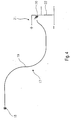
- einen Detektor für eine Vorrichtung gemäß Fig. 1,
- Fig. 5
- ein Detail der Vorrichtung gemäß Fig. 1 in Seitenansicht,
- Fig. 6
- das Detail gemäß Fig. 5 in Draufsicht.
- Ein Gemisch gebrauchter Batterien und Akkumulatoren mit unterschiedlichem elektrochemischen Zelltyp, nachfolgend kurz Zelle 10 genannt, wird über eine Dosiereinrichtung 11 einzeln nacheinander auf einem Förderer, nämlich einem Förderband 12, abgelegt. Durch das Förderband 12 werden die Zellen 10 auf einem zweiten Förderer, hier wiederum einem Förderband 13, abgelegt. Das Förderband 13 läuft schneller als das Förderband 12, so daß die Zellen 10 räumlich entzerrt werden, also der Abstand zwischen aufeinanderfolgenden Zellen 10 erhöht wird.
- Das Förderband 13 weist eine gegenüber der Horizontalen quer zur Transportrichtung geneigte Transportfläche auf. In der Darstellung gemäß Fig. 3 fällt die Transportfläche nach rechts unten ab. Um ein seitliches Herunterfallen der Zellen 10 zu verhindern, ist eine seitliche Führung 14 vorgesehen. Durch Reibung der Zellen 10 an der Führung 14 sowie durch die Neigung des Förderbandes 13 richten sich die Batterien definiert hintereinander aus und werden so einer Erkennungsstation 15 sequentiell in definierter Ausrichtung zugeführt, nämlich mit ihrer Längsachse in Transportrichtung. Dabei können die einzelnen Zellen 10 - mal mit ihrem Pluspol, mal mit ihrem Minuspol - nach vorn der Erkennungsstation 15 zugeführt werden. Dieses ist für die Erkennung des elektrochemischen Zelltyps unerheblich. Das Erkennen des elektrochemischen Zelltyps in der Erkennungsstation 15 ist jedoch erheblich erleichtert, wenn die Richtung der Längsachse der Zelle 10 gegenüber der Transportrichtung vorher festgelegt ist. Im vorliegenden Fall wurde eine Ausrichtung der Längsachse der Zelle 10 in Transportrichtung gewählt.
- In der Erkennungsstation 15 ist eine Röntgenquelle 16, im vorliegenden Fall eine Röntgenröhre, und auf der der Röntgenquelle 16 gegenüberliegenden Seite des Förderbandes 13 ein Detektor 17 vorgesehen. Röntgenquelle 16 und Detektor 17 sind im vorliegenden Fall so angeordnet, daß die Zellen 10 mit etwa senkrecht zur Längsachse der Zellen 10 gerichteter Röntgenstrahlung durchleuchtet werden.
- Der Detektor 17 mißt die auftreffende Dosisleistung, also die Gesamttransmission der Röntgenstrahlung durch die gerade zu bestimmende Zelle 10. Da aufgrund der nur sehr kurzen Zeit, die zur Bestimmung des elektrochemischen Zelltyps der gerade zu untersuchenden Zelle 10 zur Verfügung steht, nämlich maximal 30 ms, muß mit sehr energiereicher Röntgenstrahlung von der Röntgenquelle 16 gearbeitet werden. Herkömmliche Dosisleistungsmeßgeräte halten der hier erforderlichen hohen Dosisleistung von bis zu 104 Gy/h (bei z. B. 160 keV) nicht stand. Der Detektor 17 ist daher in besonderer, näher in Fig. 4 gezeigter Weise ausgebildet. Der Detektor 17 weist einen Röntgenleuchtschirm 18 auf. Durch die auf den Röntgenleuchtschirm 18 treffende Röntgenstrahlung wird dieser zum Leuchten angeregt. In gewissen Grenzen ist die Helligkeit des mit Röntgenstrahlung bestrahlten Röntgenleuchtschirms 18 in weiten Grenzen proportional zur Dosisleistung. Der Röntgenleuchtschirm 18 steht mit einem Lichtleiter 19 aus Kunststoff in Kontakt. Der Lichtleiter 19 ist einadrig ausgebildet und weist einen Durchmesser von etwa 1 mm auf. Seine Länge beträgt 10 m. Das andere Ende des Lichtleiters 19 steht mit einem Fototransistor 20 einer Fototransistorschaltung 21 in Kontakt. Der Fototransistor 20 bzw. die Fototransistorschaltung 21 ist dabei außerhalb des Strahlungsfeldes der Röntgenquelle 16 angeordnet.
- Der Fototransistor 20 ist mit einem Widerstand 22 in Reihe geschaltet. Durch Abgreifen der Spannung am Widerstand 22 wird die Helligkeit des Röntgenleuchtschirms 18 und mithin die Dosisleistung am Röntgenleuchtschirm 18 gemessen. Die abgegriffene Spannung am Widerstand 22 ist proportional zur Helligkeit und mithin zur Dosisleistung am Röntgenleuchtschirm 18.
- Damit die Röntgenstrahlung ungehindert auf den Röntgenleuchtschirm 18 treffen kann, ist die Führung 14 mit einem Durchbruch 23 versehen. Im vorliegenden Fall besteht der Detektor 17 aus zwei übereinander angeordneten Röntgenleuchtschirmen 18. Jedem Röntgenleuchtschirm 18 ist dabei ein eigener Durchbruch 23 in der Führung 14 zugeordnet. Jeder Röntgenleuchtschirm 18 ist über ein eigenes Lichtleiterkabel 19 mit einem eigenen Fototransistor 20 einer eigenen Fototransistorschaltung 21 verbunden. Durch die Verwendung von zwei Röntgenleuchtschirmen 18 übereinander können Zusatzinformationen über die Größe der gerade untersuchten Zelle 10 gewonnen werden, wodurch die eindeutige Bestimmung des elektrochemischen Zelltyps erleichtert wird.
- In der Erkennungsstation 15 werden durch eine geeignete Datenverarbeitungsanlage entsprechende Signale für eine Sortierstation 24 zum Sortieren der Zellen 10 nach ihrem elektrochemischen Zelltyp erzeugt. Die Sortierstation 24 schließt sich unmittelbar an die Erkennungsstation 15 an. Konkret ist zwischen dem Eingang der Sortierstation 24 und der Erkennungsstation 15 bzw. dem Röntgenleuchtschirm 18 etwa derselbe Abstand, wie zwischen zwei aufeinanderfolgenden Zellen 10 in der Erkennungsstation 15 vorgesehen. Im vorliegenden Fall sind in der Sortierstation 24 vier Sammelbehälter 25, 26, 27 und 28 angeordnet. In jedem der Sammelbehälter 25..28 wird ein bestimmter elektrochemischer Zelltyp einsortiert. Alternativ kann einer der Sammelbehälter 25..28 auch einer Restfraktion nicht identifizierbarer elektrochemischer Zelltypen zugeordnet sein.
- Das Förderband 13 endet unmittelbar am Eingang zur Sortierstation 24. Hier werden die Zellen 10 mit der Bandgeschwindigkeit des Förderbandes 13, im vorliegenden Fall 1 m/s bis 5m/s, insbesondere 3 m/s, abgeworfen. Der Abstand zwischen dem Obertrum des Förderbandes 13 und einem Boden 29, auf dem die Sammelbehälter 25..28 stehen, beträgt etwa 1 bis 2 m. Bei dieser Höhe ist die ungestörte, ballistische Flugbahn der Zellen 10 unabhängig von ihrem Gewicht und Format. Der Sammelbehälter 28 ist so positioniert, daß die Zellen 10 bei ungestörter, ballistischer Flugbahn in den Sammelbehälter 28 treffen. Um die Zellen 10, die in einem der anderen Sammelbehälter 25, 26 oder 27 treffen sollen, sind Druckluftdüsen 30, 31 und 32 vorgesehen, mittels derer die Zellen 10 durch Druckluftstöße von ihrer ungestörten, ballistischen Flugbahn abgelenkt werden. Durch Betätigen der Druckluftdüse 30 wird die gerade vom Förderband 13 abgeworfene Zelle 10 in den Sammelbehälter 25 abgelenkt. Durch Betätigen der Druckluftdüse 31 trifft die gerade abgeworfene Zelle 10 in den Sammelbehälter 26, und das Betätigen der Druckluftdüse 32 sorgt schließlich für ein Treffen der gerade abgeworfenen Zelle 10 in den Sammelbehälter 27.
- Jeder Druckluftdüse 30, 31 und 32 ist ein eigener Druckluftpufferbehälter 33, 34 bzw. 35 zugeordnet, durch die die Druckluftdüsen 30..32 über Zuleitungen 36 gespeist werden. Die Druckluftpufferbehälter 33..35 stehen ihrerseits in Verbindung mit einer geeigneten Druckluftquelle.
- Die Druckluftdüsen 30..32 sind konkret eine Kombination aus mehreren, nebeneinander angeordneten Druckluftdüsen, die durch schnell arbeitende Magnetventile mit einem Gesamtzeitbedarf für das Ein- und Ausschalten von weniger als 10 ms und einer daraus folgenden effektiven Druckluftblaszeit von 20 ms oder weniger einen ausreichenden Impuls auf die Zelle 10 zu übertragen, um diese nach Verlassen des Förderbandes 13 seitlich links, seitlich rechts oder zu kurz in den entsprechenden Sammelbehälter 25, 26 oder 27 abzulenken.
- Mit der hier gezeigten Sortiereinrichtung 24 können somit Zellen 10 mit vier unterschiedlichen elektrochemischen Zelltypen sortiert werden. Gegebenenfalls können auch zwei zusätzliche Sammelbehälter, in Transportrichtung des Förderbandes 13 gesehen links und rechts neben dem Sammelbehälter 28, vorgesehen sein, so daß insgesamt sechs Sammelbehälter für insgesamt sechs elektrochemische Zelltypen zur Verfügung stehen. Gegebenenfalls kann die Sortierung der Zellen 10 nach ihrem elektrochemischen Zelltyp aber auch mehrstufig erfolgen, wobei einer der Sammelbehälter 25..28, beispielsweise der Sammelbehälter 28, einer unsortierten Restfraktion zugeordnet ist. Diese unsortierte Restfraktion entspricht dann einem neuen Gemisch von Zellen 10 unterschiedlichen elektrochemischen Zelltyps, der dann erneut in einer zweiten Stufe sortiert wird. Gegebenenfalls können die Zellen 10 der Restfraktion anstatt in beispielsweise den Behälter 28 direkt auf ein weiteres Förderband geworfen werden, durch das sie wieder einer neuen Erkennungsstation und anschließend einer Sortierstation zugeführt werden. Die neue Erkennungsstation kann dabei gegebenenfalls auch nach einem anderen physikalischen Prinzip den elektrochemischen Zelltyp bestimmen.
- Trotz bester Erkennungs- und Sortiertechnik wird es letztlich unvermeidlich bleiben, daß eine Restfraktion nicht zu sortierender Zellen 10, beispielsweise aufgrund von Beschädigungen oder starken Verschmutzungen an den Zellen 10, übrig bleibt. Wichtig für eine metallurgische Verwertung der Zellen 10 ist, daß die einem bestimmten elektrochemischen Zelltyp zugeordneten Sammelbehälter mit einem Sortenreinheitsgrad von größer/gleich 99% den jeweiligen gewünschten elektrochemischen Zelltyp enthalten. Die aufgrund von Beschädigungen oder starken Verschmutzungen unsortierbaren Zellen 10 sind zahlenmäßig vernachlässigbar und können gegebenenfalls anschließend manuell sortiert, endgelagert oder auf sonstige Weise endbehandelt werden.
-
- 10
- Zelle
- 11
- Dosiereinrichtung
- 12
- Förderband
- 13
- Förderband
- 14
- Führung
- 15
- Erkennungsstation
- 16
- Röntgenquelle
- 17
- Detektor
- 18
- Röntgenleuchtschirm
- 19
- Lichtleiter
- 20
- Fötotransistor
- 21
- Fototransistorschaltung
- 22
- Widerstand
- 23
- Durchbruch
- 24
- Sortierstation
- 25
- Sammelbehälter
- 26
- Sammelbehälter
- 27
- Sammelbehälter
- 28
- Sammelbehälter
- 29
- Boden
- 30
- Druckluftdüse
- 31
- Druckluftdüse
- 32
- Druckluftdüse
- 33
- Druckluftpufferbehälter
- 34
- Druckluftpufferbehälter
- 35
- Druckluftpufferbehälter
- 36
- Zuleitung
Claims (7)
- Vorrichtung zum Sortieren von Altbatterien und/oder Altakkumulatoren (Zellen 10) nach ihrem Typ mit einer Erkennungsstation (15) zum Durchleuchten der Altbatterien und/oder Altakkumulatoren (Zellen 10) mit Röntgenstrahlen, mit einem Detektor (17) zum Messen der Dosisleistung und mit einer nachfolgenden Sortierstation (24) zum Sortieren der Altbatterien und/oder Altakkumulatoren nach ihrem Typ anhand der von dem Detektor (17) gemessenen Dosisleistung, dadurch gekennzeichnet, daß der Detektor (17) zum Messen der Dosisleistung von Röntgenstrahlung für hohe Dosisleistungen bis 104 Gy/h einen Röntgenleuchtschirm (18) und einen Fototransistor (20) aufweist, die durch einen Lichtleiter (19) aus Kunststoff miteinander verbunden sind.
- Vorrichtung nach Anspruch 1, dadurch gekennzeichnet, daß der, insbesondere einadrige, Lichtleiter (19) einen Durchmesser von 1 mm aufweist und/oder daß der Lichtleiter (19) wenigstens 1 m, insbesondere 10 m, lang ist.
- Vorrichtung nach Anspruch 1 oder 2, dadurch gekennzeichnet, daß wenigstens zwei Detektoren (17) bzw. Röntgenleuchtschirme (18) übereinander angeordnet sind.
- Vorrichtung nach einem der Ansprüche 1 bis 3, gekennzeichnet durch einen Förderer (13) zum Zuführen der Altbatterien und/oder Altakkumulatoren (Zellen 10) zu der Erkennungsstation (15), dessen Transportfläche quer zur Transportrichtung gegenüber der Horizontalen geneigt ist, wobei eine seitliche Führung (14) gegen das Herunterfallen der Altbatterien und/oder Altakkumulatoren (Zellen 10) vorgesehen ist.
- Vorrichtung nach einem der Ansprüche 1 bis 4, dadurch gekennzeichnet, daß sich der Erkennungsstation (15) unmittelbar die Sortierstation (24) anschließt.
- Vorrichtung nach Anspruch 5, dadurch gekennzeichnet, daß der Abstand der Erkennungsstation (15) und der Sortierstation (24) maximal der doppelte, vorzugsweise maximal der einfache, Abstand zweier aufeinanderfolgender Altbatterien und/oder Altakkumulatoren (Zellen 10) im Bereich der Erkennungsstation (15) ist.
- Vorrichtung nach einem der Ansprüche 1 bis 6, dadurch gekennzeichnet, daß die Altbatterien und/oder Altakkumulatoren (Zellen 10) am Eingang der Sortierstation (24) von dem Förderer (13) abwerfbar und zum Sortieren von ihrer ballistischen Flugbahn je nach Typ in unterschiedliche Richtungen, insbesondere durch Druckluftstöße, ablenkbar sind.
Applications Claiming Priority (2)
| Application Number | Priority Date | Filing Date | Title |
|---|---|---|---|
| DE2000110556 DE10010556A1 (de) | 2000-03-08 | 2000-03-08 | Detektor zum Messen der Dosisleistung sowie Vorrichtung zum Sortieren von Altbatterien oder Altakkumulatoren nach ihrem Typ |
| DE10010556 | 2000-03-08 |
Publications (2)
| Publication Number | Publication Date |
|---|---|
| EP1132992A1 EP1132992A1 (de) | 2001-09-12 |
| EP1132992B1 true EP1132992B1 (de) | 2007-04-25 |
Family
ID=7633480
Family Applications (1)
| Application Number | Title | Priority Date | Filing Date |
|---|---|---|---|
| EP20010105714 Expired - Lifetime EP1132992B1 (de) | 2000-03-08 | 2001-03-07 | Detektor zum Messen der Dosisleistung von Röntgenstrahlen sowie Vorrichtung zum Sortieren von Altbatterien und/oder Altakkumulatoren nach ihrem Typ |
Country Status (3)
| Country | Link |
|---|---|
| EP (1) | EP1132992B1 (de) |
| AT (1) | ATE360895T1 (de) |
| DE (2) | DE10010556A1 (de) |
Cited By (5)
| Publication number | Priority date | Publication date | Assignee | Title |
|---|---|---|---|---|
| DE102010012383A1 (de) | 2010-03-22 | 2011-09-22 | Sven Rausch | Sortierwaage zur automatischen Sortierung von Gegenständen |
| EP3450578A1 (de) | 2017-09-04 | 2019-03-06 | E.V.H. S.R.L. | Chemisches verfahren zur rückgewinnung von alkali- und zink-kohlenstoff-batteriekomponenten |
| EP3450122A1 (de) | 2017-09-04 | 2019-03-06 | E.V.H. S.R.L. | Station zum schneiden von aa-typ-, d-typ- und/oder c-typ-batterien, verfahren zur trennung und rückgewinnung von bestandteilen der besagten batterien und system zur durchführung solch eines verfahrens |
| CN109622424A (zh) * | 2018-12-04 | 2019-04-16 | 江门市博大新能源材料有限公司 | 一种电芯检测分选设备 |
| WO2020176627A1 (en) * | 2019-02-27 | 2020-09-03 | Li Industries, Inc. | Methods and systems for smart battery collection, sorting, and packaging |
Families Citing this family (7)
| Publication number | Priority date | Publication date | Assignee | Title |
|---|---|---|---|---|
| CN102437385B (zh) * | 2011-12-12 | 2014-03-12 | 中国电力科学研究院 | 一种电动汽车动力电池梯次利用的分级方法 |
| CN103028552B (zh) * | 2013-01-17 | 2014-12-10 | 上海美声服饰辅料有限公司 | 电子标签自动检测整理收集装置 |
| IT201900021687A1 (it) | 2019-11-20 | 2021-05-20 | Engitec Tech S P A | Impianto e procedimento di trattamento di accumulatori esausti o dismessi. |
| US11660642B1 (en) * | 2020-11-02 | 2023-05-30 | Linev Systems Us, Inc. | Method and apparatus for automatic sorting of unmarked power cells |
| CN114602818B (zh) * | 2022-03-14 | 2025-09-30 | 深圳市日联科技有限公司 | 对检测物品进行多级分拣的x射线检测系统、装置和方法 |
| CN114638834B (zh) * | 2022-05-23 | 2022-08-09 | 深圳鑫茂新能源技术有限公司 | 一种基于图像处理的废旧锂电池分类处理方法 |
| DE102024108235A1 (de) * | 2024-03-22 | 2025-09-25 | Giesecke+Devrient Currency Technology Gmbh | Sortieren von flächigen Objekten für die Herstellung von galvanischen Zellen |
Family Cites Families (10)
| Publication number | Priority date | Publication date | Assignee | Title |
|---|---|---|---|---|
| DE1035802B (de) * | 1956-01-25 | 1958-08-07 | Reich Robert W | Strahlenanzeiger in Miniaturausfuehrung |
| GB1103591A (en) * | 1964-02-25 | 1968-02-21 | Nat Res Dev | Improvements in or relating to analysing and/or sorting arrangements |
| SE422111B (sv) * | 1980-06-23 | 1982-02-15 | Asea Ab | Fiberoptiskt kopplat metdon |
| DE3335512A1 (de) * | 1983-09-30 | 1985-04-18 | Kernforschungszentrum Karlsruhe Gmbh, 7500 Karlsruhe | Neutronen- und/oder gammadetektionssystem |
| IT1200694B (it) * | 1985-07-29 | 1989-01-27 | Minnesota Mining & Mfg | Dispositivo di lettura per pannello di fosforo stimolabile |
| CA1242260A (en) * | 1986-04-24 | 1988-09-20 | Leonard Kelly | Multisorting method and apparatus |
| DE3877202D1 (de) * | 1988-10-14 | 1993-02-11 | Siemens Ag | Roentgendiagnostikeinrichtung mit einem speicherleuchtschirm. |
| AT393171B (de) * | 1989-06-20 | 1991-08-26 | Loew Hans Guenter Mag | Optoelektronische messvorrichtung zur punktfoermigen erfassung von dosis, dosisleistung und dosisverteilungen |
| GB9604140D0 (en) * | 1996-02-27 | 1996-05-01 | Spanswick Keith A | Radiation measuring apparatus |
| DE19610093A1 (de) * | 1996-03-15 | 1997-09-18 | Bsbg Bremer Sonderabfall Berat | Verfahren zum Sortieren von Altbatterien und/oder Altakkumulatoren sowie Vorrichtung zur Durchführung des Verfahrens |
-
2000
- 2000-03-08 DE DE2000110556 patent/DE10010556A1/de not_active Withdrawn
-
2001
- 2001-03-07 DE DE50112390T patent/DE50112390D1/de not_active Expired - Lifetime
- 2001-03-07 AT AT01105714T patent/ATE360895T1/de not_active IP Right Cessation
- 2001-03-07 EP EP20010105714 patent/EP1132992B1/de not_active Expired - Lifetime
Cited By (10)
| Publication number | Priority date | Publication date | Assignee | Title |
|---|---|---|---|---|
| DE102010012383A1 (de) | 2010-03-22 | 2011-09-22 | Sven Rausch | Sortierwaage zur automatischen Sortierung von Gegenständen |
| EP3450578A1 (de) | 2017-09-04 | 2019-03-06 | E.V.H. S.R.L. | Chemisches verfahren zur rückgewinnung von alkali- und zink-kohlenstoff-batteriekomponenten |
| EP3450122A1 (de) | 2017-09-04 | 2019-03-06 | E.V.H. S.R.L. | Station zum schneiden von aa-typ-, d-typ- und/oder c-typ-batterien, verfahren zur trennung und rückgewinnung von bestandteilen der besagten batterien und system zur durchführung solch eines verfahrens |
| WO2019043244A1 (en) | 2017-09-04 | 2019-03-07 | E.V.H. S.r.l. | CHEMICAL PROCESS FOR RECOVERING ALKALINE AND ZINC CARBON BATTERY COMPONENTS |
| WO2019043242A1 (en) | 2017-09-04 | 2019-03-07 | E.V.H. S.r.l. | AA, TYPE D AND / OR TYPE C BATTERY STATION, METHOD FOR SEPARATING AND RECOVERING COMPONENTS THEREOF, AND SYSTEM FOR IMPLEMENTING SUCH A METHOD |
| US11578387B2 (en) | 2017-09-04 | 2023-02-14 | Evh S.R.L. In Liquidazione | Chemical process for the recovery of alkaline and zinc-carbon battery components |
| CN109622424A (zh) * | 2018-12-04 | 2019-04-16 | 江门市博大新能源材料有限公司 | 一种电芯检测分选设备 |
| WO2020176627A1 (en) * | 2019-02-27 | 2020-09-03 | Li Industries, Inc. | Methods and systems for smart battery collection, sorting, and packaging |
| US11747290B2 (en) | 2019-02-27 | 2023-09-05 | Li Industries, Inc. | Methods and systems for smart battery collection, sorting, and packaging |
| US12521766B1 (en) | 2019-02-27 | 2026-01-13 | Li Industries, Inc. | Smart systems and methods for identification and processing of spent lithium cells |
Also Published As
| Publication number | Publication date |
|---|---|
| DE10010556A1 (de) | 2001-09-13 |
| EP1132992A1 (de) | 2001-09-12 |
| ATE360895T1 (de) | 2007-05-15 |
| DE50112390D1 (de) | 2007-06-06 |
Similar Documents
| Publication | Publication Date | Title |
|---|---|---|
| EP1132992B1 (de) | Detektor zum Messen der Dosisleistung von Röntgenstrahlen sowie Vorrichtung zum Sortieren von Altbatterien und/oder Altakkumulatoren nach ihrem Typ | |
| DE2645367C2 (de) | Vorrichtung zum Trennen von Münzen | |
| DE60218074T2 (de) | Durchflusszytometer | |
| DE19948559C1 (de) | Verfahren zur Erfassung der Partikel eines Tabakpartikel-Stroms | |
| EP2765558B1 (de) | Münzvereinzelungsvorrichtung und entsprechendes Verfahren | |
| DE3833022C2 (de) | ||
| DE918054C (de) | Geraet zum Zaehlen von Staubteilchen | |
| CH629018A5 (de) | Muenzsortiervorrichtung. | |
| DE69120225T2 (de) | Vorrichtung zur Messung der Strahlungsverseuchung von Objekten | |
| WO2006000001A1 (de) | Detektiervorrichtung zum erkennen von gegenständen in einem materialstrom | |
| EP0328126B1 (de) | Verfahren und Vorrichtung zum Sortieren von Altglas | |
| DE3007038A1 (de) | Verfahren und vorrichtung zum sortieren von erz | |
| DE2800494C3 (de) | Münzsortiervorrichtung mit Auswerferstößeln | |
| CH643359A5 (de) | Verfahren zum pruefen von produktproben und anordnung zur durchfuehrung des verfahrens. | |
| EP0096092B1 (de) | Vorrichtung zum Sortieren von Metallteilen | |
| DE3514313C2 (de) | Verfahren und Vorrichtung zur Inspektion und zum Sortieren von Glasbehältern | |
| CH645201A5 (en) | Method and device for testing the authenticity of coins | |
| DE4312550C1 (de) | Vorrichtung zur Bewertung von sich fortbewegenden Objekten | |
| WO2017063772A1 (de) | Verfahren, vorrichtung und verwendung der vorrichtung zur detektion von neutronen sowie auslese- und verarbeitungseinrichtung | |
| DE3636506A1 (de) | Spiralabtastverfahren | |
| DE19824039A1 (de) | Verfahren und Vorrichtung zur Prüfung von Schüttmaterial, insbesondere von Bauschutt und/oder Bodenaushub, auf den Gehalt an Radionukliden | |
| EP0151956A2 (de) | Vorrichtung an Bowling- bzw. Kegelbahnen zur Ermittlung von Spielergebnissen | |
| DE102010004768A1 (de) | Vorrichtung zum Sortieren von Münzen und Kassensystem | |
| CH665144A5 (en) | Checking and sorting device for mass produced items - has measuring cycle controlled by signals from sensor station in front of measuring station | |
| EP4382216B1 (de) | Verfahren und vorrichtung zum analysieren und sortieren von materialteilen |
Legal Events
| Date | Code | Title | Description |
|---|---|---|---|
| PUAI | Public reference made under article 153(3) epc to a published international application that has entered the european phase |
Free format text: ORIGINAL CODE: 0009012 |
|
| AK | Designated contracting states |
Kind code of ref document: A1 Designated state(s): AT BE CH CY DE DK ES FI FR GB GR IE IT LI LU MC NL PT SE TR |
|
| AX | Request for extension of the european patent |
Free format text: AL;LT;LV;MK;RO;SI |
|
| RIN1 | Information on inventor provided before grant (corrected) |
Inventor name: MOLCHIN, THURE Inventor name: RAUSCH, SVEN, DR. |
|
| RAP1 | Party data changed (applicant data changed or rights of an application transferred) |
Owner name: 3V CONSULTING GMBH |
|
| 17P | Request for examination filed |
Effective date: 20020312 |
|
| AKX | Designation fees paid |
Free format text: AT BE CH CY DE DK ES FI FR GB GR IE IT LI LU MC NL PT SE TR |
|
| AXX | Extension fees paid |
Free format text: AL PAYMENT 20020312;LT PAYMENT 20020312;LV PAYMENT 20020312;MK PAYMENT 20020312;RO PAYMENT 20020312;SI PAYMENT 20020312 |
|
| DAX | Request for extension of the european patent (deleted) | ||
| 17Q | First examination report despatched |
Effective date: 20040204 |
|
| GRAP | Despatch of communication of intention to grant a patent |
Free format text: ORIGINAL CODE: EPIDOSNIGR1 |
|
| GRAS | Grant fee paid |
Free format text: ORIGINAL CODE: EPIDOSNIGR3 |
|
| GRAA | (expected) grant |
Free format text: ORIGINAL CODE: 0009210 |
|
| AK | Designated contracting states |
Kind code of ref document: B1 Designated state(s): AT BE CH CY DE DK ES FI FR GB GR IE IT LI LU MC NL PT SE TR |
|
| PG25 | Lapsed in a contracting state [announced via postgrant information from national office to epo] |
Ref country code: FI Free format text: LAPSE BECAUSE OF FAILURE TO SUBMIT A TRANSLATION OF THE DESCRIPTION OR TO PAY THE FEE WITHIN THE PRESCRIBED TIME-LIMIT Effective date: 20070425 |
|
| REG | Reference to a national code |
Ref country code: GB Ref legal event code: FG4D Free format text: NOT ENGLISH |
|
| REG | Reference to a national code |
Ref country code: IE Ref legal event code: FG4D Free format text: LANGUAGE OF EP DOCUMENT: GERMAN |
|
| REG | Reference to a national code |
Ref country code: CH Ref legal event code: EP |
|
| REF | Corresponds to: |
Ref document number: 50112390 Country of ref document: DE Date of ref document: 20070606 Kind code of ref document: P |
|
| PG25 | Lapsed in a contracting state [announced via postgrant information from national office to epo] |
Ref country code: SE Free format text: LAPSE BECAUSE OF FAILURE TO SUBMIT A TRANSLATION OF THE DESCRIPTION OR TO PAY THE FEE WITHIN THE PRESCRIBED TIME-LIMIT Effective date: 20070725 |
|
| PG25 | Lapsed in a contracting state [announced via postgrant information from national office to epo] |
Ref country code: ES Free format text: LAPSE BECAUSE OF FAILURE TO SUBMIT A TRANSLATION OF THE DESCRIPTION OR TO PAY THE FEE WITHIN THE PRESCRIBED TIME-LIMIT Effective date: 20070805 |
|
| PG25 | Lapsed in a contracting state [announced via postgrant information from national office to epo] |
Ref country code: PT Free format text: LAPSE BECAUSE OF FAILURE TO SUBMIT A TRANSLATION OF THE DESCRIPTION OR TO PAY THE FEE WITHIN THE PRESCRIBED TIME-LIMIT Effective date: 20070925 |
|
| NLV1 | Nl: lapsed or annulled due to failure to fulfill the requirements of art. 29p and 29m of the patents act | ||
| GBV | Gb: ep patent (uk) treated as always having been void in accordance with gb section 77(7)/1977 [no translation filed] |
Effective date: 20070425 |
|
| REG | Reference to a national code |
Ref country code: IE Ref legal event code: FD4D |
|
| EN | Fr: translation not filed | ||
| PG25 | Lapsed in a contracting state [announced via postgrant information from national office to epo] |
Ref country code: NL Free format text: LAPSE BECAUSE OF FAILURE TO SUBMIT A TRANSLATION OF THE DESCRIPTION OR TO PAY THE FEE WITHIN THE PRESCRIBED TIME-LIMIT Effective date: 20070425 Ref country code: DK Free format text: LAPSE BECAUSE OF FAILURE TO SUBMIT A TRANSLATION OF THE DESCRIPTION OR TO PAY THE FEE WITHIN THE PRESCRIBED TIME-LIMIT Effective date: 20070425 Ref country code: IE Free format text: LAPSE BECAUSE OF FAILURE TO SUBMIT A TRANSLATION OF THE DESCRIPTION OR TO PAY THE FEE WITHIN THE PRESCRIBED TIME-LIMIT Effective date: 20070425 |
|
| PLBE | No opposition filed within time limit |
Free format text: ORIGINAL CODE: 0009261 |
|
| STAA | Information on the status of an ep patent application or granted ep patent |
Free format text: STATUS: NO OPPOSITION FILED WITHIN TIME LIMIT |
|
| 26N | No opposition filed |
Effective date: 20080128 |
|
| PG25 | Lapsed in a contracting state [announced via postgrant information from national office to epo] |
Ref country code: GB Free format text: LAPSE BECAUSE OF FAILURE TO SUBMIT A TRANSLATION OF THE DESCRIPTION OR TO PAY THE FEE WITHIN THE PRESCRIBED TIME-LIMIT Effective date: 20070425 Ref country code: IT Free format text: LAPSE BECAUSE OF FAILURE TO SUBMIT A TRANSLATION OF THE DESCRIPTION OR TO PAY THE FEE WITHIN THE PRESCRIBED TIME-LIMIT Effective date: 20070425 Ref country code: GR Free format text: LAPSE BECAUSE OF FAILURE TO SUBMIT A TRANSLATION OF THE DESCRIPTION OR TO PAY THE FEE WITHIN THE PRESCRIBED TIME-LIMIT Effective date: 20070726 Ref country code: FR Free format text: LAPSE BECAUSE OF FAILURE TO SUBMIT A TRANSLATION OF THE DESCRIPTION OR TO PAY THE FEE WITHIN THE PRESCRIBED TIME-LIMIT Effective date: 20071221 |
|
| PGFP | Annual fee paid to national office [announced via postgrant information from national office to epo] |
Ref country code: CH Payment date: 20080320 Year of fee payment: 8 |
|
| PGFP | Annual fee paid to national office [announced via postgrant information from national office to epo] |
Ref country code: LU Payment date: 20080320 Year of fee payment: 8 |
|
| REG | Reference to a national code |
Ref country code: CH Ref legal event code: PUE Owner name: UNI-CYC TECHNOLOGIEBERATUNGS-, PROJEKTENTWICKLUNG Free format text: 3V CONSULTING GMBH#KNOCHENHAUERSTRASSE 36/37#28195 BREMEN (DE) -TRANSFER TO- UNI-CYC TECHNOLOGIEBERATUNGS-, PROJEKTENTWICKLUNGS- UND VERTRIEBS-GMBH#VAN-HEUKELUM-STR. 10#27568 BREMERHAVEN (DE) |
|
| PGFP | Annual fee paid to national office [announced via postgrant information from national office to epo] |
Ref country code: BE Payment date: 20080321 Year of fee payment: 8 |
|
| PG25 | Lapsed in a contracting state [announced via postgrant information from national office to epo] |
Ref country code: MC Free format text: LAPSE BECAUSE OF NON-PAYMENT OF DUE FEES Effective date: 20080331 |
|
| PG25 | Lapsed in a contracting state [announced via postgrant information from national office to epo] |
Ref country code: FR Free format text: LAPSE BECAUSE OF FAILURE TO SUBMIT A TRANSLATION OF THE DESCRIPTION OR TO PAY THE FEE WITHIN THE PRESCRIBED TIME-LIMIT Effective date: 20070425 |
|
| PG25 | Lapsed in a contracting state [announced via postgrant information from national office to epo] |
Ref country code: CY Free format text: LAPSE BECAUSE OF FAILURE TO SUBMIT A TRANSLATION OF THE DESCRIPTION OR TO PAY THE FEE WITHIN THE PRESCRIBED TIME-LIMIT Effective date: 20070425 |
|
| BERE | Be: lapsed |
Owner name: UNI-CYC TECHNOLOGIEBERATUNGS- PROJEKTENTWICKLUNGS- Effective date: 20090331 |
|
| REG | Reference to a national code |
Ref country code: CH Ref legal event code: PL |
|
| PG25 | Lapsed in a contracting state [announced via postgrant information from national office to epo] |
Ref country code: LI Free format text: LAPSE BECAUSE OF NON-PAYMENT OF DUE FEES Effective date: 20090331 Ref country code: CH Free format text: LAPSE BECAUSE OF NON-PAYMENT OF DUE FEES Effective date: 20090331 |
|
| PG25 | Lapsed in a contracting state [announced via postgrant information from national office to epo] |
Ref country code: BE Free format text: LAPSE BECAUSE OF NON-PAYMENT OF DUE FEES Effective date: 20090331 |
|
| PGFP | Annual fee paid to national office [announced via postgrant information from national office to epo] |
Ref country code: AT Payment date: 20100322 Year of fee payment: 10 |
|
| PG25 | Lapsed in a contracting state [announced via postgrant information from national office to epo] |
Ref country code: TR Free format text: LAPSE BECAUSE OF FAILURE TO SUBMIT A TRANSLATION OF THE DESCRIPTION OR TO PAY THE FEE WITHIN THE PRESCRIBED TIME-LIMIT Effective date: 20070425 |
|
| PG25 | Lapsed in a contracting state [announced via postgrant information from national office to epo] |
Ref country code: LU Free format text: LAPSE BECAUSE OF NON-PAYMENT OF DUE FEES Effective date: 20090307 |
|
| REG | Reference to a national code |
Ref country code: DE Ref legal event code: R082 Ref document number: 50112390 Country of ref document: DE Representative=s name: ZACCO DR. PETERS UND PARTNER, DE |
|
| PG25 | Lapsed in a contracting state [announced via postgrant information from national office to epo] |
Ref country code: AT Free format text: LAPSE BECAUSE OF NON-PAYMENT OF DUE FEES Effective date: 20110307 |
|
| PGFP | Annual fee paid to national office [announced via postgrant information from national office to epo] |
Ref country code: DE Payment date: 20120331 Year of fee payment: 12 |
|
| REG | Reference to a national code |
Ref country code: DE Ref legal event code: R082 Ref document number: 50112390 Country of ref document: DE Representative=s name: ZACCO DR. PETERS UND PARTNER, DE Effective date: 20110921 Ref country code: DE Ref legal event code: R082 Ref document number: 50112390 Country of ref document: DE Representative=s name: ZACCO DR. PETERS UND PARTNER, DE Effective date: 20121115 Ref country code: DE Ref legal event code: R081 Ref document number: 50112390 Country of ref document: DE Owner name: REDUX TECHNOLOGY GMBH, DE Free format text: FORMER OWNER: UNI-CYC TECHNOLOGIEBERATUNGS-, PROJEKTENTWICKLUNGS- UND VERTRIEBS GMBH, 27568 BREMERHAVEN, DE Effective date: 20121115 |
|
| REG | Reference to a national code |
Ref country code: DE Ref legal event code: R119 Ref document number: 50112390 Country of ref document: DE Effective date: 20131001 |
|
| PG25 | Lapsed in a contracting state [announced via postgrant information from national office to epo] |
Ref country code: DE Free format text: LAPSE BECAUSE OF NON-PAYMENT OF DUE FEES Effective date: 20131001 |