EP1132553A2 - Serrure cylindrique - Google Patents
Serrure cylindrique Download PDFInfo
- Publication number
- EP1132553A2 EP1132553A2 EP01102368A EP01102368A EP1132553A2 EP 1132553 A2 EP1132553 A2 EP 1132553A2 EP 01102368 A EP01102368 A EP 01102368A EP 01102368 A EP01102368 A EP 01102368A EP 1132553 A2 EP1132553 A2 EP 1132553A2
- Authority
- EP
- European Patent Office
- Prior art keywords
- pin
- stylus
- center
- bodies
- cup
- Prior art date
- Legal status (The legal status is an assumption and is not a legal conclusion. Google has not performed a legal analysis and makes no representation as to the accuracy of the status listed.)
- Granted
Links
Images


Classifications
-
- E—FIXED CONSTRUCTIONS
- E05—LOCKS; KEYS; WINDOW OR DOOR FITTINGS; SAFES
- E05B—LOCKS; ACCESSORIES THEREFOR; HANDCUFFS
- E05B19/00—Keys; Accessories therefor
- E05B19/0017—Key profiles
-
- E—FIXED CONSTRUCTIONS
- E05—LOCKS; KEYS; WINDOW OR DOOR FITTINGS; SAFES
- E05B—LOCKS; ACCESSORIES THEREFOR; HANDCUFFS
- E05B27/00—Cylinder locks or other locks with tumbler pins or balls that are set by pushing the key in
-
- E—FIXED CONSTRUCTIONS
- E05—LOCKS; KEYS; WINDOW OR DOOR FITTINGS; SAFES
- E05B—LOCKS; ACCESSORIES THEREFOR; HANDCUFFS
- E05B27/00—Cylinder locks or other locks with tumbler pins or balls that are set by pushing the key in
- E05B27/0003—Details
- E05B27/0017—Tumblers or pins
- E05B27/0021—Tumblers or pins having movable parts
-
- E—FIXED CONSTRUCTIONS
- E05—LOCKS; KEYS; WINDOW OR DOOR FITTINGS; SAFES
- E05B—LOCKS; ACCESSORIES THEREFOR; HANDCUFFS
- E05B27/00—Cylinder locks or other locks with tumbler pins or balls that are set by pushing the key in
- E05B27/0078—Asymmetrical tumbler pins, e.g. with a key operating on a radial protrusion of a tumbler pin
Definitions
- a device of the type mentioned is known from DE-U-7 818 276, which consists of a stator and a rotor. Latching rows running in the axial direction are arranged in the stator and the rotor. Each tumbler row has tumblers which consist of a pen element and a stylus body. The tumblers arranged above a main horizontal are to be moved to a center that is in the center of the rotor. The tumblers arranged below the main horizontal are to be moved to a center that lies below the center of the rotor. It is disadvantageous that the rotor diameter and the stator thickness must be of the same length so that five or more tumblers can be provided to secure the locking secret. As a result, the lock body has a very large outside diameter.
- From CH-A-651 350 is a cylinder lock with a reversible key known in which there is a circular rotor in cross section can move in a hollow cylindrical stator.
- the Cylinder lock has several rows of tumblers. So that one wider reversible key can be used are five Tumblers are provided, three of which are on one and two on another center are directed in the rotor.
- the stator in relation to Rotor whose outer diameter and thus the cylinder lock too large. So that the stylus bodies dismissed the closing secret can, the scanning recesses are in the narrow and long sides of a reversible key with a rectangular cross section brought in.
- a hollow cylindrical stator is inserted a core, in which pin recesses are made.
- the stator is surrounded by a river body.
- the pin recesses are with core and Housing pins equipped.
- the core has one in its peripheral surface freely opening key channel, to the side a locking ball is arranged in a spherical recess.
- a key can be inserted into the key channel
- Cross-section is 8-shaped.
- the top circle of the Eight contains keyholes and key recesses lower circle of eight a ball recess. Both circles of the are 8-shaped in cross-section through a short key and narrow waist area. In one configuration as a reversible key, the two circles with mirrored, recesses rotated by 180 °.
- the disadvantage is that due to the space available only one Half of the round core with four rows of pins can be equipped. One half of the reversible key actuated the core and body pins and the other the locking ball. The waist area has no task when unlocking of the core against the stator.
- DE-U-8 717 534 is one of flat keys and Lock cylinder existing locking device known.
- the Lock cylinder is in addition to the spring-loaded tumbler pins equipped with an intermediate plate.
- In the A platelet receiving chamber is arranged on the cylinder surface, which is offset from the angle of rotation with that with intermediate plates equipped pin bore and in the same cross-sectional plane this lies.
- the flat keys are on one side each with pin recesses for the tumbler pins in a row Mistake.
- DE-B-2 546 551 there is a cylinder lock with a flat key described.
- a series of pins is arranged in the core. With a key that can be inserted into a key channel is, the pins are applied so that the core opposite a cylinder is released.
- the key channel is only inclined relative to the pin plane, so that this the key notches on the flat key have an acute angle are.
- From DE-A-2 059 573 is a cylinder lock with a Key known.
- pin tumblers in the core of the locking cylinder as a case pin, a core pin that matches the case pin opposite, and a coupling link to the plane of the housing and core pin is arranged at a right angle.
- DE-C-2 660 959 describes a locking cylinder with a reversible key described. There is only one in the locking cylinder Core pin row arranged.
- the core pin rows during the insertion movement of the Get a good lead they have in the Key channel protruding core pins a gradation to which an injection taking place beyond a key channel level with which the core pins on the support the opposite duct wall.
- EP-B-0 313 864 is a lock cylinder with pin tumblers known.
- stator and the core are in cross section
- pin elements offset by 90 ° arranged as pin tumblers.
- pin elements arranged opposite one of the four pin elements are positioned offset by 45 °.
- a locking cylinder is known from CH-B-451 740, which has a round core in cross section, in which inserted a key slot and the in a cylindrical Stator is inserted.
- a key slot and the in a cylindrical Stator is inserted.
- the advantages achieved with the invention are in particular in that they are directed towards the first center Pin elements include other pin elements that point to the second center are directed, have the same housing pin body and only the stylus bodies versus their cup body to move to the second center.
- the thickness of the stator body with a large number of pin elements that are aimed at both centers can be reduced to about half the radius length of the rotor. So that the locking cylinder of the locking device as a whole smaller.
- the first center can be a main center and in the Center of the essentially circular in cross section Core body and the second center can be an angle pin center be the center point on a central axis of the core body opposite. Whether the angle pin center above or lies below the center point depends on the particular Design of the cylinder lock.
- the stator and core can be along the central axis be divided into a first and a second level.
- At least one row of first pin elements can be level with first Stylus bodies and at least a number of second Be assigned to pin elements with second stylus bodies.
- the assignment of the individual parts of the pin elements to two Levels enables the use of reversible keys.
- the first and the second pin elements can each have one have biased housing pin body. This bias can be realized by springs or another elastic material become. The preload ensures that the pin elements always occupy a certain position.
- a housing and a cup pin body of the second pin elements can on the main center while those in the cup pen bodies movably inserted second stylus body be directed to the angle pin center.
- the housing and the cup pin body At a first angle, the housing and the cup pin body the second pin elements with respect to the main pin center and the second stylus bodies of the second Pin elements at a second angle with respect to the angle pin center opposite one at right angles to the central axis lying main horizontal in the core body his.
- This ensures that the housing and cup pin body the second pin elements in their movements behave just like the parts of the first pin elements.
- the Angling the second stylus body of the second pin elements on the other hand ensures that the stylus body in the Protrude pin recess.
- the pin elements can be positioned in several main pin axes become.
- main horizontal which is circular in cross-section Kern divides, lie in a first and a second Main pin axis a first and a second of the first Pin elements.
- main pin axis In a third and fourth main pin axis, each at a third angle to the main horizontal can be a third and a fourth of the first Pin elements can be arranged. This will result in the top Half of the core and the stator body four first pin elements positioned.
- first and a second angle pin axis which in the first angle to the main horizontal can be inclined a first and a second housing and cup pin body and in a first and second tappet axis first plunger body with a first of the second stylus bodies and a second tappet body with a second one second stylus body of the second pin elements arranged his. This will add the exact location of the two introduced fifth and sixth pin elements exactly Are defined.
- the first and the second cup pin body can each one Have cup recess.
- This cup recess can be rounded and / or be formed over a wide area.
- Tappet bodies can be moved into these cup recesses, which are arranged in the second stylus body.
- the plunger body can partially with a plunger hemisphere to lock. This will implement the two Direction of movement directed movement of the second pin elements guaranteed.
- the cup recess, the second stylus body and the second plunger bodies can be of different lengths his. This allows the secret of the two to be closed define existing pen elements.
- the first and second stylus bodies can be one Have a rounded cap. This rounded pen cap eases the scanning of the inserted in the key recess Key.
- the pen cap can as a partial pen ball and the second stylus bodies be designed as a pin hemisphere.
- the core pin bodies and stylus bodies of the first pin elements and the first and second cup pin bodies and the housing pin body of the second pin elements can their opposite surface elements rounded, spherical and / or beveled. This is a Twisting the core body in the stator body when unlocking the first and second pin elements secured.
- pin recesses in the core body as first pin element recesses be arranged. Connect to the pin recesses tappet recesses as second pin recesses. On the plunger cutouts in turn close the scanning pin cutouts for the second stylus bodies as the third Pin recesses.
- the key recess moves the individual bodies of the first and second pin elements in these recesses. Limits of the recesses ensure that the respective Body assume a defined end position. But your length realizes the specific key secret of a certain one Locking cylinder.
- the second stylus body be guided in separate stylus recesses. Hereby is an exact scanning of the secret of the inserted key possible.
- the individual parts of the cylinder lock such as the stator body, the core body, the bodies of the first pin elements, the Body of the second pin elements, can be made of metal, hard plastic, Sintered material or the like.
- Metal can be steel or brass.
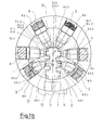
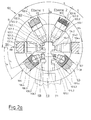
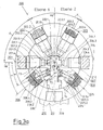
- 1a to 1e is a lock cylinder 20 and its Parts, in Figs. 2a to 2f, a lock cylinder 120 and its Parts and a locking cylinder 220 in FIGS. 3a to 3i with its parts shown in section.
- 4 is a key body of a key for the Lock cylinder 20, 120, 220 shown.
- Fig. La and 1b, 2a and 2b and 3a and 3b show pin elements 1, 2, 3, 4, 5, 6, 101, 102, 103, 104, 105, 106, 201, 202, 203, 204, 205, 206 arranged.
- These pin elements form a tumbler row from which several in the longitudinal direction of the castle, for. B. six lying one behind the other and modified to realize the Locked secret are arranged.
- the pin elements 1, ..., 4, 101, ..., 104 and 201, ..., 204 are located in the upper half of the by a main horizontal HW split core and stator body.
- the pin elements 5, 6, 105, 106, 205, 206, hereinafter referred to as additional pin elements 5, 6, 105, 106, 205, 206, are below this Main horizontal.
- the pin element 1, 101, 201 is in a main pin axis HT 1 , which lies in the main horizontal HW
- the pin element 2, 102, 202 is in a main pin axis HT 2 , which is offset at an angle V with respect to the main pin axis HT 1 in a main pin axis HT 3 which is offset at an angle V from the main pin axis HT 2
- the pin element 3, 103, 203 is in a main pin axis HT 4 which is offset by an angle V from both the main horizontal axis and the main pin axis HT 3
- the four main pin axes HT 1 , ... HT 4 go through a main center Z, which is directed at the center of the core body. This means that all four pin elements are directed towards the main center.
- an angle pin axis WT 5 which is offset at an angle Y from the main horizontal, there are two bodies 5.3, 5.4 and Further parts 5.1, 5.2 of the additional pin element 5, 105, 205 are arranged in a ram axis ST 5 , which is offset by an angle X with respect to the horizontal.
- an angular pin axis WT 6 are two bodies 6.3, 6.4, of the additional pin element 6, 106, 206 and in a ram axis ST 6 , which is also offset by the angle X from the main horizontal, further parts 6.1, 6.2, of the additional pin element 6, 106, 206 arranged.
- the two angle pin axes WT 5 and WT 6 are both directed towards the main center Z. It is essential to the invention that the two tappet axes ST 5 and ST 6 intersect in an angle pin center ZW.
- Both the main pin center and the angle pin center lie on a central axis MA, the stator and Divide the core body into a level 1 and a level 2.
- Level 1 is straight lying pin elements 2, 102, 202, pin elements 1, 101, 201 and an angled additional pin element 6, 106, 206 and assigned to level 2 in a row one behind the other pin elements 3, 103, 203, 4, 104, 204 and an angled additional pin elements 5, 105, 205.
- stator and core body 8 9, 108, 109, 208, 209 are recesses in the course of the specified main and angle pin axes introduced (cf. in particular Fig. 1 A, 2 A, 3 A).
- the four pin elements 1, ..., 4, 101, ..., 104, 201, ..., 204 have the same structure. They consist of a body pin body 1.4, ..., 4.4, the preloaded in the stator recesses 8.1, ..., 8.4, 108.1, ... 108.4, 208.1, ... 208.4 positioned is.
- stator recesses of the stator body and the ones in front Pin recesses of the core body 9, 109, 209 have in essentially the same diameter so that the core pin body and the housing pin body of the pin elements 1, ..., 4, 101, ..., 104, 201, ..., 204 move back and forth in these.
- the plunger pin bodies go as shown in FIGS. 1a and 1b, 2a and 2b 3a and 3b show, in a stylus body 1.1, 2.1, 3.1, 4.1, 101.1, 102.1, 103.1, 104.1, 201.1, 202.1, 203.1, 204.1 about.
- the stylus bodies face the plunger pin bodies one paragraph and have a lower one than these Diameter. They move with the plunger pin bodies 1.2, ... in the stylus and plunger recesses, which have the same diameter.
- additional pin elements is essential to the invention. They are for the individual locking cylinders 20, 120, 220 differently trained.
- the additional pin elements 5, 6 of the locking cylinder 20 have la and 1b on a housing pin body 5.4, 6.4, each biased in the stator recess 8.5, 8.6 are moving.
- a cup pin body is located above the housing pin body 5.4, 6.4 5.3, 6.3. Both cup pin bodies 5.3, 6.3 are of the same design and have the same diameter as the housing pin body 5.4, 6.4, so that they both in the stator recess 8.5, 8.6 as well as in the one above Can move pin recess.
- the cup pin body 5.3, 6.3 is in detail in Fig. 1d shown. It has a cup pin recess 5.8, 6.8 on, which is polygonal in cross section.
- the cup holder is a cup round 5.7, 6.7 opposite.
- the cup rounding is spherical and is one Bevel surround.
- Fig. 1a shows Ram body 5.2, 6.2 used, each of which is a stylus body 5.1, 6.1 connects.
- the ram body 5.2, 6.2 has such a diameter that it is in the tappet recess 9.5.2, 9.6.2 is to be managed.
- the depth of the plunger recess limits the maximum stroke of the ram body.
- the stylus body 5.1, 6.1 has such an outer diameter, that it is in the stylus recess 9.5.1, 9.6.1 lead is.
- the plunger body with the subsequent stylus body is shown individually in Fig. le.
- the ram body 5.2, 6.2 closes with a plunger hemisphere 5.6, 6.6 and the Stylus body 5.1, 6.1 with a pen hemisphere 5.5, 6.5 from.
- the plunger hemisphere allows the plunger to remain undisturbed move in the cup recess of the cup pin body can.
- the plunger hemisphere ensures that the closing secret can be scanned easily and accurately.
- the core body is along a parting plane 12 in the stator body 8 rotatable.
- Fig. 1a it is clear that both the cup as well as the housing pin body in this parting plane are located in Fig. 1b outside the parting plane are positioned.
- the additional pin elements 105, 106 of the lock cylinder 120 according to 2a and 2b are similar to those of the lock cylinder 20 built.
- Housing pin bodies are located in the stator recesses 108.5, 108.6 105.4, 106.4, which are mounted preloaded. about the housing pin body is in the pin recesses above 109.5.3, 109.6.3 each a cup pen body 105.3, 106.3 stored. Because both the cup and the body pin body as well as the stator and pin recesses have the same diameter, they can move freely move in this.
- the two housing pin bodies 105.4 are located, 106.4 and the two cup pin bodies 105.3, 106.3 in one Splitting plane 112.
- the cup pin body 105.3, 106.3 is shown individually in Fig. 2d. It has a cup recess 105.8, 106.8 which is multi-faceted. This cup recess lies a cup round 105.7, 106.7 opposite, which is spherical and is cut at an angle.
- a plunger body 105.2 which is in a stylus body 105.1 passes and is shown in detail in Fig. 2 e.
- the Tappet body 102.5 has a tappet hemisphere 105.6 that has a larger diameter than the tappet body.
- the stylus body 105.1 closes with a plunger hemisphere 105.5 from.
- the plunger body 106.2 to which a stylus body 106.1 connects, which is shown individually in Fig. 2f.
- the plunger body 106.2 also has a plunger hemisphere here 106.6, which has a larger diameter than one, with which completes the stylus body 106.5. Both stylus bodies are of different lengths.
- the plunger and the The stylus body according to FIG. 2e together has a plunger length L 105 and a plunger length L 106 according to FIG. 2f.
- the two additional pin elements 205, 206 of the locking cylinder 3a according to FIGS. 3a and 3b point towards the ones described above a number of differences.
- stator recesses 208.5 and 208.6 Is located in the stator recesses 208.5 and 208.6 a housing pin body 205.4, 206.4, which is mounted preloaded is.
- the cup pin body has a cup recess 205.8, 206.8.
- the cup recess is in rounded in this case and has a radius of curvature R.
- To the Rounding area closes at an opening angle of 30 ° opening area of a hollow truncated cone recess on.
- the cup pin body is opposite the cup recess provided with a cup rounding 205.7, 206.7, the is spherical and a circumferential cutting surface having.
- the cup pin body has a cup length L 205.7.
- 3e is a further embodiment of a cup pin body shown, which is designated with 205.3 '. Also it has a rounded cup recess 205.8 'to which also connects a frustoconical opening and the a crowned cup round 205.7 'is opposite.
- the cup pin body 205.3 ' has a cup length L 205.7 ', which is longer than the cup length L 205.7.
- the different Cup lengths are of different depths Cup recesses connected, which hold securely and Enable the tappet body to be moved in them, the distance between the cup recess and the cup rounding is essentially the same ..
- a plunger body is designated, on which one connected with 209.5.1 stylus body, the is shown individually in Fig. 3h.
- the plunger body 205.2 closes with a plunger hemisphere 205.6, which is the same Diameter as the tappet body.
- the stylus body 205.1 ends in a pin hemisphere 205.5.
- Probe and plunger body have a ram length L 205, meanwhile the Ram only has a single length L 205.2.
- scanning and plunger bodies 105.1 ', 205.2' are in a shorter ram length L 205 'shown.
- the single length L 205.2 ' is essentially equal to the individual length L. 200.5.2.
- the stylus body designated 206.1 and designated 206.2 Ram bodies are constructed in the same way as the one described Stylus body 205.1 and plunger body 205.2, as shown in detail in Fig. 3f.
- the tappet body closes with a tappet hemisphere 206.6 and the pen body with a pen half ball 206.5. Together they have a plunger length L 206 that is essentially is equal to the ram length L 205.
- the plunger body has one Individual length L 206.2, which is essentially the individual length L 205.2 corresponds.
- a shorter plunger body 206.1 ' is connected to an equally long plunger body 206.2'. Both together have a plunger length L 206 ', while the plunger body has a single length L 206.2'. Both the plunger body and the stylus body are rounded.
- all four plunger bodies are designed identically, to which stylus bodies of different lengths are connected.
- a reversible key 11, 111, 211 is shown in FIG. 4.
- the Reversible key 11 is also in Fig. Lc, the reversible key 111 in Fig. 2c and the reversible key 211 in Fig. 3c shown.
- the reversible key has one Key body 11.0 on that of three interconnected There are single bodies that are round, oval, rectangular or can be square in cross section.
- 11.20 denotes a main body of the key body 11.0, which is opposed by a second main body 11.21. There is no web connection between the two main bodies, but a third body as an independent additional body arranged. This creates a configuration in cross-section, which is 8- (eight-) shaped, over which an O-shaped Body is arranged.
- the two main bodies and the additional body of the key body 11.0 are provided with a key profile 11.40, an insertion of the reversible key into the respective Closing device 20, 120, 220 allows.
- the key can be used as a reversible key, is the key body 11.0 along a turning axis WA divided diagonally so that one main body 11.10, 11.21 an additional part body 11.31, 11.32 is assigned. Will this divided two parts along the turning axis WA and around Twisted by 180 ° C, they share the same secret.
- A lies between the turning axis WA and the central axis MA Pitch angle ⁇ of approximately 45 °.
- main body 11.20 which the four on the Main center Z directional stylus body 1.1, ..., 4.1 scanned, are the two stylus body by the additional body 11.30 5.1 and 6.1 scanned on the angle pin center ZW are directed.
- the scanning movements of the stylus bodies 5.1 and 6.1 of the additional pen elements are transmitted at an angle.
- the movement of the tappet axes ST 5 , ST 6 onto the angle pin axes WT 5 , WT 6 is made possible in that the tappet pin body rotates with its tappet hemisphere in the cup recess of the cup pin body 5.3, 6.3. If the two stylus bodies 5.1, 6.1 snap into one of the scanning recesses, as shown in particular in FIG. 4a, the plunger body is advanced so that the two cup stylus bodies 5.3, 6.3 and the housing stylus bodies 5.4, 6.4 are located in the parting plane 12.
- T 1 , T 2 are tappet depths for the tappet body.
- T 3 indicates a scanning depth of the cup body in the pin recess.
- T 4 is a cup depth.
- a cup core stroke with H 206.8 a cup stator stroke, designated H 206.4, a housing pin stroke.
- H 205.4 also denotes a housing pin lift.
- L 202 is the length of the stylus body to the core pin body of the pin element 202 and with L 203.2 a length of the pin element 3 thereof Designated stylus body up to its housing pin body.
Applications Claiming Priority (2)
| Application Number | Priority Date | Filing Date | Title |
|---|---|---|---|
| DE10011111 | 2000-03-09 | ||
| DE10011111A DE10011111A1 (de) | 2000-03-09 | 2000-03-09 | Schließzylinder |
Publications (3)
| Publication Number | Publication Date |
|---|---|
| EP1132553A2 true EP1132553A2 (fr) | 2001-09-12 |
| EP1132553A3 EP1132553A3 (fr) | 2003-01-29 |
| EP1132553B1 EP1132553B1 (fr) | 2004-07-14 |
Family
ID=7633851
Family Applications (1)
| Application Number | Title | Priority Date | Filing Date |
|---|---|---|---|
| EP01102368A Expired - Lifetime EP1132553B1 (fr) | 2000-03-09 | 2001-02-02 | Serrure cylindrique |
Country Status (4)
| Country | Link |
|---|---|
| EP (1) | EP1132553B1 (fr) |
| AT (1) | ATE271171T1 (fr) |
| DE (2) | DE10011111A1 (fr) |
| ES (1) | ES2223657T3 (fr) |
Cited By (2)
| Publication number | Priority date | Publication date | Assignee | Title |
|---|---|---|---|---|
| EP1333135A1 (fr) * | 2002-02-01 | 2003-08-06 | August Knapp Schliesstechnik GmbH | Serrure cylindrique |
| EP1333136A1 (fr) * | 2002-02-01 | 2003-08-06 | August Knapp Schliesstechnik GmbH | Serrure cylindrique |
Citations (8)
| Publication number | Priority date | Publication date | Assignee | Title |
|---|---|---|---|---|
| DE2059573A1 (de) | 1970-12-03 | 1972-06-08 | Linde Ag | Autogen-Schneidbrenner |
| DE2546551B2 (de) | 1975-10-17 | 1978-01-05 | Fa. Wilhelm Karrenberg, 5620 VeIbert | Zylinderschloss mit flachschluessel |
| DE7818276U1 (de) | 1977-06-30 | 1979-02-22 | Bauer Kaba Ag Sicherheits-Schliessysteme, Wetzikon (Schweiz) | Zylinderschloss mit zugehoerigem flachschluessel |
| CH651350A5 (en) | 1980-09-05 | 1985-09-13 | Ernst Keller | Cylinder lock with a reversible key |
| DE2660959C2 (fr) | 1976-02-19 | 1987-07-09 | Dom Sicherheitstechnik | |
| DE8717534U1 (fr) | 1987-08-10 | 1989-01-19 | Dom-Sicherheitstechnik Gmbh & Co Kg, 5040 Bruehl, De | |
| EP0313864B1 (fr) | 1987-10-26 | 1993-03-03 | Julius Niederdrenk Kg | Serrure cylindrique à goupilles |
| DE4336776A1 (de) | 1993-10-27 | 1995-05-04 | Sikora Industrieelektronik | Vorrichtung zur Messung des Durchhangs eines mit einer Isolierschicht ummantelten Leiters in einem Vulkanisierrohr |
Family Cites Families (3)
| Publication number | Priority date | Publication date | Assignee | Title |
|---|---|---|---|---|
| SE422481B (sv) * | 1979-07-10 | 1982-03-08 | Gkn Stenman Ab | Cylinderlas-nyckelkombination, nyckel till denna samt sett att tillverka nyckeln |
| DE3817494A1 (de) * | 1988-05-21 | 1989-11-23 | Karrenberg Fa Wilhelm | Schliessvorrichtung, bestehend aus flachschluessel und schliesszylinder |
| DE4336476A1 (de) * | 1993-10-26 | 1995-04-27 | Bks Gmbh | Schlüssel für Schließzylinder, insbesondere von Schließanlagen |
-
2000
- 2000-03-09 DE DE10011111A patent/DE10011111A1/de not_active Withdrawn
-
2001
- 2001-02-02 EP EP01102368A patent/EP1132553B1/fr not_active Expired - Lifetime
- 2001-02-02 DE DE50102826T patent/DE50102826D1/de not_active Expired - Lifetime
- 2001-02-02 ES ES01102368T patent/ES2223657T3/es not_active Expired - Lifetime
- 2001-02-02 AT AT01102368T patent/ATE271171T1/de not_active IP Right Cessation
Patent Citations (8)
| Publication number | Priority date | Publication date | Assignee | Title |
|---|---|---|---|---|
| DE2059573A1 (de) | 1970-12-03 | 1972-06-08 | Linde Ag | Autogen-Schneidbrenner |
| DE2546551B2 (de) | 1975-10-17 | 1978-01-05 | Fa. Wilhelm Karrenberg, 5620 VeIbert | Zylinderschloss mit flachschluessel |
| DE2660959C2 (fr) | 1976-02-19 | 1987-07-09 | Dom Sicherheitstechnik | |
| DE7818276U1 (de) | 1977-06-30 | 1979-02-22 | Bauer Kaba Ag Sicherheits-Schliessysteme, Wetzikon (Schweiz) | Zylinderschloss mit zugehoerigem flachschluessel |
| CH651350A5 (en) | 1980-09-05 | 1985-09-13 | Ernst Keller | Cylinder lock with a reversible key |
| DE8717534U1 (fr) | 1987-08-10 | 1989-01-19 | Dom-Sicherheitstechnik Gmbh & Co Kg, 5040 Bruehl, De | |
| EP0313864B1 (fr) | 1987-10-26 | 1993-03-03 | Julius Niederdrenk Kg | Serrure cylindrique à goupilles |
| DE4336776A1 (de) | 1993-10-27 | 1995-05-04 | Sikora Industrieelektronik | Vorrichtung zur Messung des Durchhangs eines mit einer Isolierschicht ummantelten Leiters in einem Vulkanisierrohr |
Cited By (2)
| Publication number | Priority date | Publication date | Assignee | Title |
|---|---|---|---|---|
| EP1333135A1 (fr) * | 2002-02-01 | 2003-08-06 | August Knapp Schliesstechnik GmbH | Serrure cylindrique |
| EP1333136A1 (fr) * | 2002-02-01 | 2003-08-06 | August Knapp Schliesstechnik GmbH | Serrure cylindrique |
Also Published As
| Publication number | Publication date |
|---|---|
| ES2223657T3 (es) | 2005-03-01 |
| ATE271171T1 (de) | 2004-07-15 |
| EP1132553A3 (fr) | 2003-01-29 |
| EP1132553B1 (fr) | 2004-07-14 |
| DE10011111A1 (de) | 2001-09-13 |
| DE50102826D1 (de) | 2004-08-19 |
Similar Documents
| Publication | Publication Date | Title |
|---|---|---|
| DE3051010C2 (fr) | ||
| EP1350909B1 (fr) | Clé pour serrures à barillet | |
| DE60119767T2 (de) | Wendeschlüssel und zugehöriger schliesszylinder | |
| DE1678096B2 (de) | Einrichtung zum erschweren des unbefugten betaetigens in einem drehzylinderschloss | |
| EP0067388B1 (fr) | Serrure cylindrique | |
| EP3922788A1 (fr) | Ébauche de clé et clé destinée au fonctionnement d'un cylindre de disque, ainsi que procédé de fabrication d'une telle ébauche de clé et de clé | |
| DE2533494B2 (de) | Schließzylinder mit Stiftzuhaltungen und Schlüssel | |
| EP0213069B1 (fr) | Serrure de sécurité | |
| EP0607993B1 (fr) | Ensemble de serrures à cylindre, une serrure à cylindre pour former un tel ensemble, dispositif de verrouillage hierarchique à la base d'un tel ensemble, clé pour la serrure à cylindre et méthode de fabrication de la clé | |
| DE3129459A1 (de) | Schliesszylinder od.dgl. | |
| EP1333136B1 (fr) | Serrure cylindrique | |
| EP1132553B1 (fr) | Serrure cylindrique | |
| EP0574752B1 (fr) | Clé et cylindre de serrure correspondant notamment cyclindre de serrure profilé | |
| EP0814222B1 (fr) | Clé plate pour serrure cylindrique | |
| DE60224802T2 (de) | Zylinderschlossschlüsselkombination | |
| EP0625624A1 (fr) | Serrure cylindrique | |
| EP1132551B1 (fr) | Dispositif de verrouillage avec clé réversible | |
| EP3339538B1 (fr) | Ébauche de clé pour fabrication d'un clé pour une serrure cylindrique, clé, dispositif de fermeture et procédure | |
| EP3205796B1 (fr) | Clé pour un barillet, barillet et dispositif de fermeture | |
| DE69908894T2 (de) | Zylinderschloss mit Kupplungseinrichtung | |
| EP1333135B1 (fr) | Serrure cylindrique | |
| DE102005030408B3 (de) | Zylinderschloss | |
| EP0118910A2 (fr) | Cylindre de fermeture | |
| EP3428371A1 (fr) | Barillet de serrure, cylindre de serrure, clé, dispositif de fermeture, serrure à cylindre et procédé correspondant | |
| DE102017101783A1 (de) | Verbesserter Schlüssel für einen Schließzylinder, Schließvorrichtung und Verfahren |
Legal Events
| Date | Code | Title | Description |
|---|---|---|---|
| PUAI | Public reference made under article 153(3) epc to a published international application that has entered the european phase |
Free format text: ORIGINAL CODE: 0009012 |
|
| AK | Designated contracting states |
Kind code of ref document: A2 Designated state(s): AT BE CH CY DE DK ES FI FR GB GR IE IT LI LU MC NL PT SE TR |
|
| AX | Request for extension of the european patent |
Free format text: AL;LT;LV;MK;RO;SI |
|
| PUAL | Search report despatched |
Free format text: ORIGINAL CODE: 0009013 |
|
| AK | Designated contracting states |
Designated state(s): AT BE CH CY DE DK ES FI FR GB GR IE IT LI LU MC NL PT SE TR |
|
| AX | Request for extension of the european patent |
Extension state: AL LT LV MK RO SI |
|
| RIC1 | Information provided on ipc code assigned before grant |
Ipc: 7E 05B 19/00 B Ipc: 7E 05B 19/02 B Ipc: 7E 05B 27/06 A Ipc: 7E 05B 27/00 B |
|
| 17P | Request for examination filed |
Effective date: 20030723 |
|
| AKX | Designation fees paid |
Designated state(s): AT BE CH CY DE DK ES FI FR GB GR IE IT LI LU MC NL PT SE TR |
|
| GRAP | Despatch of communication of intention to grant a patent |
Free format text: ORIGINAL CODE: EPIDOSNIGR1 |
|
| GRAS | Grant fee paid |
Free format text: ORIGINAL CODE: EPIDOSNIGR3 |
|
| GRAA | (expected) grant |
Free format text: ORIGINAL CODE: 0009210 |
|
| AK | Designated contracting states |
Kind code of ref document: B1 Designated state(s): AT BE CH CY DE DK ES FI FR GB GR IE IT LI LU MC NL PT SE TR |
|
| PG25 | Lapsed in a contracting state [announced via postgrant information from national office to epo] |
Ref country code: IT Free format text: LAPSE BECAUSE OF FAILURE TO SUBMIT A TRANSLATION OF THE DESCRIPTION OR TO PAY THE FEE WITHIN THE PRESCRIBED TIME-LIMIT;WARNING: LAPSES OF ITALIAN PATENTS WITH EFFECTIVE DATE BEFORE 2007 MAY HAVE OCCURRED AT ANY TIME BEFORE 2007. THE CORRECT EFFECTIVE DATE MAY BE DIFFERENT FROM THE ONE RECORDED. Effective date: 20040714 Ref country code: FI Free format text: LAPSE BECAUSE OF FAILURE TO SUBMIT A TRANSLATION OF THE DESCRIPTION OR TO PAY THE FEE WITHIN THE PRESCRIBED TIME-LIMIT Effective date: 20040714 Ref country code: TR Free format text: LAPSE BECAUSE OF FAILURE TO SUBMIT A TRANSLATION OF THE DESCRIPTION OR TO PAY THE FEE WITHIN THE PRESCRIBED TIME-LIMIT Effective date: 20040714 Ref country code: IE Free format text: LAPSE BECAUSE OF FAILURE TO SUBMIT A TRANSLATION OF THE DESCRIPTION OR TO PAY THE FEE WITHIN THE PRESCRIBED TIME-LIMIT Effective date: 20040714 |
|
| REG | Reference to a national code |
Ref country code: GB Ref legal event code: FG4D Free format text: NOT ENGLISH |
|
| REG | Reference to a national code |
Ref country code: CH Ref legal event code: EP |
|
| GBT | Gb: translation of ep patent filed (gb section 77(6)(a)/1977) |
Effective date: 20040714 |
|
| REF | Corresponds to: |
Ref document number: 50102826 Country of ref document: DE Date of ref document: 20040819 Kind code of ref document: P |
|
| REG | Reference to a national code |
Ref country code: IE Ref legal event code: FG4D Free format text: GERMAN |
|
| PG25 | Lapsed in a contracting state [announced via postgrant information from national office to epo] |
Ref country code: GR Free format text: LAPSE BECAUSE OF FAILURE TO SUBMIT A TRANSLATION OF THE DESCRIPTION OR TO PAY THE FEE WITHIN THE PRESCRIBED TIME-LIMIT Effective date: 20041014 Ref country code: SE Free format text: LAPSE BECAUSE OF FAILURE TO SUBMIT A TRANSLATION OF THE DESCRIPTION OR TO PAY THE FEE WITHIN THE PRESCRIBED TIME-LIMIT Effective date: 20041014 Ref country code: DK Free format text: LAPSE BECAUSE OF FAILURE TO SUBMIT A TRANSLATION OF THE DESCRIPTION OR TO PAY THE FEE WITHIN THE PRESCRIBED TIME-LIMIT Effective date: 20041014 |
|
| PG25 | Lapsed in a contracting state [announced via postgrant information from national office to epo] |
Ref country code: LU Free format text: LAPSE BECAUSE OF NON-PAYMENT OF DUE FEES Effective date: 20050202 Ref country code: CY Free format text: LAPSE BECAUSE OF FAILURE TO SUBMIT A TRANSLATION OF THE DESCRIPTION OR TO PAY THE FEE WITHIN THE PRESCRIBED TIME-LIMIT Effective date: 20050202 |
|
| PG25 | Lapsed in a contracting state [announced via postgrant information from national office to epo] |
Ref country code: CH Free format text: LAPSE BECAUSE OF NON-PAYMENT OF DUE FEES Effective date: 20050228 Ref country code: LI Free format text: LAPSE BECAUSE OF NON-PAYMENT OF DUE FEES Effective date: 20050228 Ref country code: MC Free format text: LAPSE BECAUSE OF NON-PAYMENT OF DUE FEES Effective date: 20050228 |
|
| REG | Reference to a national code |
Ref country code: ES Ref legal event code: FG2A Ref document number: 2223657 Country of ref document: ES Kind code of ref document: T3 |
|
| REG | Reference to a national code |
Ref country code: IE Ref legal event code: FD4D |
|
| ET | Fr: translation filed | ||
| PLBE | No opposition filed within time limit |
Free format text: ORIGINAL CODE: 0009261 |
|
| STAA | Information on the status of an ep patent application or granted ep patent |
Free format text: STATUS: NO OPPOSITION FILED WITHIN TIME LIMIT |
|
| 26N | No opposition filed |
Effective date: 20050415 |
|
| REG | Reference to a national code |
Ref country code: CH Ref legal event code: PL |
|
| PG25 | Lapsed in a contracting state [announced via postgrant information from national office to epo] |
Ref country code: PT Free format text: LAPSE BECAUSE OF NON-PAYMENT OF DUE FEES Effective date: 20041214 |
|
| PGFP | Annual fee paid to national office [announced via postgrant information from national office to epo] |
Ref country code: AT Payment date: 20090224 Year of fee payment: 9 Ref country code: ES Payment date: 20090205 Year of fee payment: 9 |
|
| PGFP | Annual fee paid to national office [announced via postgrant information from national office to epo] |
Ref country code: NL Payment date: 20090226 Year of fee payment: 9 |
|
| PGFP | Annual fee paid to national office [announced via postgrant information from national office to epo] |
Ref country code: BE Payment date: 20090302 Year of fee payment: 9 |
|
| PGFP | Annual fee paid to national office [announced via postgrant information from national office to epo] |
Ref country code: FR Payment date: 20090219 Year of fee payment: 9 |
|
| PGFP | Annual fee paid to national office [announced via postgrant information from national office to epo] |
Ref country code: DE Payment date: 20100308 Year of fee payment: 10 Ref country code: GB Payment date: 20100217 Year of fee payment: 10 |
|
| BERE | Be: lapsed |
Owner name: AUG. *WINKHAUS G.M.B.H. & CO. K.G. Effective date: 20100228 |
|
| REG | Reference to a national code |
Ref country code: NL Ref legal event code: V1 Effective date: 20100901 |
|
| REG | Reference to a national code |
Ref country code: FR Ref legal event code: ST Effective date: 20101029 |
|
| PG25 | Lapsed in a contracting state [announced via postgrant information from national office to epo] |
Ref country code: AT Free format text: LAPSE BECAUSE OF NON-PAYMENT OF DUE FEES Effective date: 20100202 |
|
| PG25 | Lapsed in a contracting state [announced via postgrant information from national office to epo] |
Ref country code: FR Free format text: LAPSE BECAUSE OF NON-PAYMENT OF DUE FEES Effective date: 20100301 Ref country code: NL Free format text: LAPSE BECAUSE OF NON-PAYMENT OF DUE FEES Effective date: 20100901 |
|
| PG25 | Lapsed in a contracting state [announced via postgrant information from national office to epo] |
Ref country code: BE Free format text: LAPSE BECAUSE OF NON-PAYMENT OF DUE FEES Effective date: 20100228 |
|
| REG | Reference to a national code |
Ref country code: ES Ref legal event code: FD2A Effective date: 20110407 |
|
| PG25 | Lapsed in a contracting state [announced via postgrant information from national office to epo] |
Ref country code: ES Free format text: LAPSE BECAUSE OF NON-PAYMENT OF DUE FEES Effective date: 20110328 |
|
| PG25 | Lapsed in a contracting state [announced via postgrant information from national office to epo] |
Ref country code: ES Free format text: LAPSE BECAUSE OF NON-PAYMENT OF DUE FEES Effective date: 20100203 |
|
| GBPC | Gb: european patent ceased through non-payment of renewal fee |
Effective date: 20110202 |
|
| REG | Reference to a national code |
Ref country code: DE Ref legal event code: R119 Ref document number: 50102826 Country of ref document: DE Effective date: 20110901 |
|
| PG25 | Lapsed in a contracting state [announced via postgrant information from national office to epo] |
Ref country code: GB Free format text: LAPSE BECAUSE OF NON-PAYMENT OF DUE FEES Effective date: 20110202 |
|
| PG25 | Lapsed in a contracting state [announced via postgrant information from national office to epo] |
Ref country code: DE Free format text: LAPSE BECAUSE OF NON-PAYMENT OF DUE FEES Effective date: 20110901 |