EP1132552A2 - Schloss mit Zuhaltungen - Google Patents
Schloss mit Zuhaltungen Download PDFInfo
- Publication number
- EP1132552A2 EP1132552A2 EP01105563A EP01105563A EP1132552A2 EP 1132552 A2 EP1132552 A2 EP 1132552A2 EP 01105563 A EP01105563 A EP 01105563A EP 01105563 A EP01105563 A EP 01105563A EP 1132552 A2 EP1132552 A2 EP 1132552A2
- Authority
- EP
- European Patent Office
- Prior art keywords
- tumblers
- key
- rotation
- axis
- lock according
- Prior art date
- Legal status (The legal status is an assumption and is not a legal conclusion. Google has not performed a legal analysis and makes no representation as to the accuracy of the status listed.)
- Granted
Links
Images



Classifications
-
- E—FIXED CONSTRUCTIONS
- E05—LOCKS; KEYS; WINDOW OR DOOR FITTINGS; SAFES
- E05B—LOCKS; ACCESSORIES THEREFOR; HANDCUFFS
- E05B35/00—Locks for use with special keys or a plurality of keys ; keys therefor
- E05B35/08—Locks for use with special keys or a plurality of keys ; keys therefor operable by a plurality of keys
- E05B35/083—Locks for use with special keys or a plurality of keys ; keys therefor operable by a plurality of keys with changeable combination
-
- E—FIXED CONSTRUCTIONS
- E05—LOCKS; KEYS; WINDOW OR DOOR FITTINGS; SAFES
- E05B—LOCKS; ACCESSORIES THEREFOR; HANDCUFFS
- E05B21/00—Locks with lamelliform tumblers which are not set by the insertion of the key and in which the tumblers do not follow the movement of the bolt e.g. Chubb-locks
Definitions
- the invention relates to a lock with tumblers in one flat lock case, with a bolt slidably arranged in the lock case is, the tumblers arranged pivotable about an axis of rotation are the tumblers in their position relative to the axis of rotation in the direction of their surface are adjustable, the adjustment being substantially perpendicular to the direction of displacement of the bolt and for pivoting the tumblers Key is provided.
- the invention further relates to a method for recoding a lock with tumblers, the tumblers in one Lock case by means of a key about an axis of rotation in a predetermined Be brought in position and by means of a rotatable by the key Actuator a bolt is moved in the lock case, and wherein the key can only be removed in one position and positioned in several positions is.
- Locks of the generic type are already known. Using a key which has a key bit with incisions of different depths thin plates, preferably metal plates, referred to as tumblers are pivoted to different degrees around a predetermined pivot point. Each of the tumblers is provided with at least one recess in which at least engages part of a locking bolt. Locks of the generic type are equipped with several such tumblers, so that they are as described above have to be pivoted with a corresponding key, to align the recesses with each other so that the locking bar or Parts of the locking bolt can now engage in this uniform recess. Around for example, if the key is lost, such a lock on another To recode the keys, other tumblers or the existing ones must be used in a different order.
- the fence slats are provided with teeth that are spring-loaded Coding device are fixed in their position.
- a recoding we operated a recoding pin in the lock case and axially inwards pressed in order to ensure that when the key is turned, i.e. when Closing process, the coding device no longer in the teeth of the fence slats intervenes and thus their fixation is released.
- the recoding pin remains in this pressed position because it has a Cone is held.
- the tumblers are the key to what is possible after a rotation of 180 ° raised by the key teeth during the closing process and take one new position.
- the fence slats are moved across the transom, since the legs of the fence slats are still connected to the tumblers stand.
- the recoding pin becomes again released and automatically comes out of its depressed position in its initial position, since it is spring-loaded.
- the recoding is done by changing the position of the legs in the tumblers intervene, is changed relative to the bolt.
- Such recodings are relatively expensive because a plurality of parts are used to the to achieve the desired recoding.
- a generic lock is also known from DE-PS 565 027.
- the tumblers face away from the bolt End slot-like recesses in which a web engages. Different Coding can be done by a different engagement of the web be inserted into one of the recesses. For adjustment it is necessary to move the bridge within the lock case, creating a large Lock case is required.
- the object of the invention is to develop a lock which is preferably unlocked in such a way that the recoding is easier to handle and the parts used are minimized or simplified in order to reduce the costs.
- the solution to this problem provides that the axis of rotation of the tumblers is formed by a lug on a rotary element which, according to a feature further developing the invention, is accessible and rotatable from outside the lock case.
- the rotating element is positively connected to a locking element, which is equipped with a backdrop that is made of a guide element that with the bolt is connected, is acted upon. This ensures that Lock on a new key can be adjusted without the tumblers exchange.
- the nose will fix the tumblers in their pivot position.
- the shape of the nose is designed so that it fits into the corresponding notches the interlocks intervenes.
- the tumblers are of identical shape in particular, so that when mounting the lock no different tumblers in a predetermined Order must be installed. This results in an economic advantage with regard to the availability of the tumblers and on the other hand, simplification of assembly, since the use of identical Tumblers no detailed assembly instructions need to be given.
- the identity of the tumblers extends in particular to the Tourkananl and the closing curve. Due to the switchability of the tumblers using of the rotary element in combination with a toothing can the tumblers can also be arranged in such a way that the necessary security requirements for such a lock are met.
- the notches in the tumblers are preferably designed as a row of teeth.
- the rotary element with a commercially available Screwdriver can be swiveled.
- an execution is also conceivable where the rotating element is pivoted with a commercially available hexagon wrench becomes.
- the locking element is of particular importance; this is with a backdrop, in which a guide element that is fixed with the bolt connected, intervenes.
- the backdrop is designed so that it only pivots is possible in a predetermined position of the bolt.
- means for guiding the key are provided, which are designed for example as a mandrel and / or as an actuating element, wherein the mandrel engages the tip of the key and the actuator is actively connected to the key. Through the actuator the bolt moved over a driver.
- the tumblers are designed with beads executed that executed differently with neighboring tumblers are. This ensures that the tumblers do not lie flat on one another, but are spaced apart in each of their pivot positions. On an elaborate Deburring can thus be dispensed with.
- the tumblers are in each of their Swivel position loaded with the same spring force.
- an elastic element is provided, For example, to use an elastomer profile, so that the tumblers in their Longitudinal direction - in relation to the direction of movement of the bolt - slightly are movable.
- An advantageous embodiment of the lock according to the invention provides that a shielding element between the means for guiding the key and the tumblers is arranged, or that the tumblers are designed so that they always have the same initial spring force.
- an actuating element for articulating the tumblers is provided, or that the tumblers transverse to their direction of rotation an elastic element is applied.
- the form of the tumblers is chosen so that they are in each of their zero positions -
- the bolt is in the closed position and no key is applied or actuator - the same distance from the spring rest to Have axis of rotation of the key and thus with the same initial spring force be charged. It also prevents spying, since it cannot be determined which tumbler is still pivoted; just as little it is possible to determine which one via the restoring force of the spring End position for the guard locking is determined. Also, for example, cannot a miniature lens can be used to determine which tumbler through which key cut is acted upon by an actuator that with the
- the key is in operative connection and is preferably equipped with a projection is, each of the tumblers is articulated at the same point and thus uniform contact traces are generated on all tumblers.
- the actuating element has only one slot-like one Opening so that all-round scanning is prevented.
- This slit-like opening also causes the beard of the key to deflect the tumblers.
- the actuator is designed so that when in use for example a wrong key or a key-like object although twisting is possible, the possible twisting angle is limited becomes. This also limits the possible scanning angle in the same way.
- the actuating element has a driver, which enables the bolt to be moved.
- This driver is designed that in the event of violence, for example due to a predetermined breaking point, shears and thus prevents the bolt from moving.
- the actuator is made of thermoplastic, so that this is destroyed with increased heat and thus also that Moving the bolt is prevented.
- the latch has leg-like projections, which are carried out with at least one nose are. These projections, in connection with the lugs, ensure that always an area of the bolt in connection with the tumblers stands. The effect of the elastic element is thus supported.
- a lock is shown schematically in perspective, which shows a lock case 1 with the key 6 inserted. Subareas of the The lock case 1 is shown broken out to cover extensive tumblers 3 to make it recognizable that the springs 4 always against an actuating element 5 to press.
- the bolt 2 is guided in the lock case 1 and can only be in its Longitudinal axis are moved when the tumblers 3 into 6 via the key predetermined position are brought. Furthermore, there is an axis of rotation 8 in FIG. 1 the tumblers 3 can be seen, which is connected to a locking element 7.
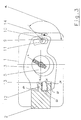
- FIG. 2 shows an example of a tumbler 3 with a portion of the bolt 2 in its closed position.
- the key 6 can be removed in this position.
- Rotating element 11 with an attached nose 9, about which the tumblers 3 pivot stands in its starting position with a tooth of a row of teeth 10 in engagement.
- the pivoting of the rotating element 11 prevented by a guide element, not shown, with the locking element 7 is connected, a pivoting of the rotary element 11 is prevented.
- Figure 3 shows the position of the lock during a recoding.
- the actuating element 5 and the key 6 are from the zero position a in one first locking position b has been rotated and thus the tumblers 3 in dependence the corresponding height of the key bit by a corresponding Angle has been pivoted about the axis of rotation 8.
- Leg-like projections 12 of the Bolts 2 engage in recesses 13 of the tumblers 3.
- the rotating element 11 by a predetermined angle ⁇ can be pivoted, the nose 9, which is on the rotary element 11th is out of engagement from the teeth 10 of the tumblers 3.
- the actuation of the rotating element 11 is from outside the lock case 1 possible. In this position of the bolt 2, the pivoting of the rotating element 11 enables the locking element because of the design of a backdrop 7 is released.
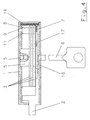
- FIG. 4 The interplay of the individual parts is illustrated again in FIG. 4.
- Key 6 and actuating element 5 lie on a common axis of rotation, wherein the actuating element 5 is fixed in the lock case 1.
- a guide element 17 on the latch 2 is in a setting of the locking element 7 in engagement.
- the locking element 7 is positively connected to the rotating element 11 on which the Nose 9 is located, which engages in the teeth 10 of the tumblers 3.
- the tumblers 3 are pivotable about this nose 9.
- the contact edge of the nose 9 forms thus the axis of rotation 8 of the tumblers 3.
- the rotating element 11 is also guided in the lock case 1 and is accessible from the outside.
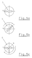
- FIG. 5 again illustrates the individual positions a - c of the key 6.
- Figure 5a shows the starting position a.
- the first position b is shown in FIG. 5b, this is after a predetermined rotation of the key 6 and Actuator 5 reached.
- the second position c is shown in FIG. 5c, this corresponds again to position a according to FIG. 5a.
- Individual positions can be provided by means of a spring-loaded ball markings or be placed outside the castle.
- FIGS. 6 to 8 Another embodiment of the invention is shown in FIGS. 6 to 8.
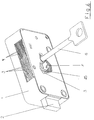
- the perspective view of the lock according to Figure 6 shows the lock case 1 with the bolt 2 and inserted key 6. Through the partially broken The tumblers 3 and springs are shown in the upper area 4 recognizable, which act on the tumblers 3.
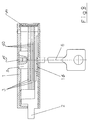
- FIG. 1 A longitudinal section through the lock case 1 is shown in FIG.
- the one in the closed position standing latch 2 has leg-like projections 12 which with Noses 21 are provided. These lugs 21 ensure an early investment of the Bolt 2 on the tumblers 3 and simulate in connection with tooth-like Projections 60 on the tumblers 3 engage the bolt 2.
- the tumblers 3 can be pivoted about the axis of rotation 9 in the direction ⁇ .
- the tumbler 3 is designed so that the distance X is constant in each of its zero positions, regardless of the position taken Pivot around the axis of rotation 9. This also ensures that the initial spring force generated by the springs 4 for all zero positions is equal to.
- Each tumbler 3 is designed with a bead 40 which is spaced apart each adjacent tumbler 3 guaranteed.
- the key 6 used which is guided by a key guide - here a mandrel 15 is in operative connection with the actuating element 5.
- the key beard can be brought into engagement with the tumblers 3 via the slot-like opening 18 are and deflects them differently due to the height of the beard. Due to the protrusion 50 attached to the actuating element 5, each tumbler 3 hinged in the same place; this creates uniform contact tracks generated, whereby a conclusion on the articulation point by the key bit is prevented.
- FIG. 8 illustrates the spacing of the tumblers 3 through the beads 40. Furthermore, the action on the tumblers 3 is through the elastic element 14 shown and the actuating element 5, which over the Driver 6 is connected to the bolt 2. The one designed as mandrel 15 Key guide element for the key 6 is anchored in the lock case 1.
Landscapes
- Lock And Its Accessories (AREA)
Abstract
Description
- Figur 1
- eine teilweise geschnittene perspektivische Darstellung einer ersten Ausführungsform eines Schlosses;
- Figur 2
- das Schloss gemäß Figur 1 in verriegelter Stellung;
- Figur 3
- das Schloß gemäß den Figuren 1 und 2 während eines Verfahrensschrittes zum Umkodieren;
- Figur 4
- das Schloss gemäß den Figuren 1 bis 3 im Längsschnitt;
- Figur 5a - c
- drei Schlüsselstellungen im Schloss gemäß den Figuren 1 bis 4;
- Figur 6
- eine teilweise geschnittene perspektivische Darstellung einer zweiten Ausführungsform eines Schlosses;
- Figur 7
- das Schloss gemäß Figur 6 im Längsschnitt und
- Figur 8
- das Schloss gemäß den Figuren 6 und 7 im Querschnitt.
- 1
- Schlosskasten
- 2
- Riegel
- 3
- Zuhaltungen
- 4
- Feder für Zuhaltung 3
- 5
- Betätigungselement für Riegel 2
- 6
- Schlüssel
- 7
- Verriegelungselement
- 8
- Schwenkachse der Zuhaltung 3
- 9
- Nase
- 10
- Auskerbungen in Zuhaltung 3
- 11
- Drehelement
- 12
- Beinartige Vorsprünge des Riegels 2
- 13
- Aussparung in Zuhaltung 3
- 14
- Elastikelement
- 15
- Dorn
- 16
- Mitnehmer für Riegel 2
- 17
- Führungselement
- 18
- schlitzartige Öffnung in 7
- 21
- Nase an 9
- 25
- Abschirmelement
- 40
- Sicke
- 50
- Vorsprung an 7
- 60
- Zahnartige Vorsprünge an 3
- α
- Verdrehwinkel an 7
- x
- Abstand von Schlüsseldrehachse zu Federauflage
- ω
- Drehrichtung der Zuhaltungen 3
Claims (34)
- Schloss mit Zuhaltungen (3) in einem im wesentlichen flachen Schlosskasten (1), wobei im Schlosskasten (1) ein Riegel (2) verschiebbar angeordnet ist, die Zuhaltungen (3) um eine Drehachse (8) verschwenkbar angeordnet sind, die Zuhaltungen (3) in ihrer Lage relativ zur Drehachse (8) in Richtung ihrer Fläche verstellbar sind, wobei die Verstellung im wesentlichen rechtwinklig zur Verschieberichtung des Riegels (2) erfolgt und zum Verschwenken der Zuhaltungen (3) ein Schlüssel (6) vorgesehen ist,
dadurch gekennzeichnet, dass die Drehachse (8) der Zuhaltungen (3) durch eine Nase (9) an einem Drehelement (11) gebildet wird. - Schloss nach Anspruch 1,
dadurch gekennzeichnet, dass die Zuhaltungen (3) hinsichtlich ihrer Form identisch ausgebildet sind. - Schloss nach Anspruch 1,
dadurch gekennzeichnet, dass das Drehelement (11) von außerhalb des Schlosskastens (1) zugänglich und verdrehbar ist. - Schloss nach Anspruch 1,
dadurch gekennzeichnet, dass das Drehelement (11) mit einem Verriegelungselement (7), vorzugsweise formschlüssig, verbunden ist. - Schloss nach Anspruch 4,
dadurch gekennzeichnet, dass das Verriegelungselement (7) mit einer Kulisse ausgestattet ist, die von einem Führungselement, das mit dem Riegel (2) verbunden ist, beaufschlagt ist. - Schloss nach einem oder mehreren der Ansprüche 1 bis 5,
dadurch gekennzeichnet, dass die Nase (9) die Zuhaltungen (3) in ihrer Drehpunktlage fixiert. - Schloss nach einem oder mehreren der Ansprüche 1 bis 6,
dadurch gekennzeichnet, dass die Nase (9) so ausgebildet ist, dass sie der Form einer Auskerbung (10) angepaßt ist. - Schloss nach einem oder mehreren der vorhergehenden Ansprüche,
dadurch gekennzeichnet, dass die Auskerbung (10) der Zuhaltung (3) als Zahnreihe ausgeführt ist. - Schloss nach einem oder mehreren der vorhergehenden Ansprüche,
dadurch gekennzeichnet, dass zur Führung des Schlüssels (6) Mittel (15) vorgesehen sind. - Schloss nach Anspruch 9,
dadurch gekennzeichnet, dass die Mittel (15) zur Führung des Schlüssels ein Dorn und/oder ein Betätigungselement sind. - Schloss nach Anspruch 9,
dadurch gekennzeichnet, dass zwischen den Mitteln (15) zur Führung des Schlüssels (6) und den Zuhaltungen (3) ein Abschirmelement (25) angeordnet ist. - Schloss nach einem oder mehreren der vorhergehenden Ansprüche,
dadurch gekennzeichnet, dass ein Betätigungselement (5) zur Anlenkung der Zuhaltungen (3) vorgesehen ist. - Schloss nach einem oder mehreren der vorhergehenden Ansprüche,
dadurch gekennzeichnet, dass quer zur Drehrichtung (ω) der Zuhaltungen (3) ein elastisches Element (14) angeordnet ist. - Schloss nach einem oder mehreren der vorhergehenden Ansprüche,
dadurch gekennzeichnet, dass die Zuhaltungen (3) mit Sicken (14) ausgeführt sind. - Schloss nach Anspruch 4,
dadurch gekennzeichnet, dass die Sicken (14) benachbarter Zuhaltungen (3) unterschiedlich ausgeführt sind. - Schloss nach Anspruch 4 oder 15,
dadurch gekennzeichnet, dass die Zuhaltungen (3) durch die Sicken (14) in jeder ihrer Schwenkstellung beabstandet sind. - Schloss nach einem oder mehreren der vorhergehenden Ansprüche,
dadurch gekennzeichnet, dass die Zuhaltungen (3) durch federbelastete Elemente (4) beaufschlagt sind. - Schloss nach einem der vorhergehenden Ansprüche,
dadurch gekennzeichnet, dass die Zuhaltungen (3) so ausgeführt sind, dass sie stets mit einer gleichen Anfangsfederkraft beaufschlagt sind. - Schloss nach einem der Ansprüche 17 oder 18,
dadurch gekennzeichnet, dass die Zuhaltungen (3) so ausgeführt sind, dass jede Zuhaltung (3) bei gleich großer Auslenkung mit einer gleich großen Federkraft beaufschlagt wird. - Schloß nach Anspruch 19
dadurch gekennzeichnet, dass die Zuhaltungen (3) so ausgeführt sind, dass jede Zuhaltung (3) bei gleich großer Auslenkung, unabhängig von der Einstellposition der Zuhaltung (3) um ihre Drehachse (8), mit einer gleich großen Federkraft beaufschlagt wird. - Schloss nach Anspruch 13,
dadurch gekennzeichnet, dass die Zuhaltungen (3) durch das Elastikelement (14) beaufschlagt sind, so dass diese quer zu ihrer Schwenkrichtung verschiebbar sind. - Schloss nach Anspruch 12,
dadurch gekennzeichnet, dass das Betätigungselement (5) und das Verriegelungselement (7) mit einer zueinander korrespondierenden Kulisse ausgeführt sind. - Schloss nach einem oder mehreren der vorhergehenden Ansprüche,
dadurch gekennzeichnet, dass der Riegel (2) beinartige Vorsprünge (9) aufweist. - Schloss nach Anspruch 23,
dadurch gekennzeichnet, dass die Vorsprünge (9) des Riegels (2) mit mindestens einer Nase (10) ausgeführt sind. - Schloss nach Anspruch 13,
dadurch gekennzeichnet, dass das elastische Element (14) ein Elastomerprofil ist. - Schloss nach Anspruch 11,
dadurch gekennzeichnet, dass das Abschirmelement (25) fest mit dem Schlosskasten (1) verbunden ist. - Schloss nach Anspruch 12,
dadurch gekennzeichnet, dass das Betätigungselement (5) mit einem Vorsprung (50) ausgestattet ist. - Schloss nach Anspruch 27,
dadurch gekennzeichnet, dass das Betätigungselement (5) eine schlitzartige Öffnung (18) aufweist. - Schloss nach Anspruch 27 oder 28,
dadurch gekennzeichnet, dass das Betätigungselement (5) mit einem Mitnehmer (16) ausgeführt ist. - Schloss nach Anspruch 29,
dadurch gekennzeichnet, dass der Mitnehmer (16) eine Sollbruchstelle aufweist. - Schloss nach Anspruch 12 oder mindestens einem der Ansprüche 27 bis 30,
dadurch gekennzeichnet, dass das Betätigungselement (5) aus Kunststoff ist. - Verfahren zum Umkodieren eines Schlosses mit Zuhaltungen (3),
wobei die Zuhaltungen (3) in einem Schlosskasten (1) mittels eines Schlüssels (6) um eine Drehachse (8) in eine vorbestimmte Lage gebracht werden und mittels eines durch den Schlüssel (6) verdrehbarem Betätigungselement (5) ein Riegel (2) im Schlosskasten (1) verschoben wird, wobei der Schlüssel (6) nur in einer Position abziehbar und in mehreren Positionen (a, b, c) positionierbar ist,
dadurch gekennzeichnet, dass die Umkodierung in folgender Abfolge durchgeführt wird:a) Verdrehen des Schlüssels von einer Nullstellung (a) in eine erste Raststellung (b), wobei die Zuhaltungen (3) um eine Drehachse (8) verschwenkt werden und die beinartigen Vorsprünge des Riegels (2) in die Aussparungen der Zuhaltungen (3) eingreifen.b) Verschwenken der Drehachse (8) um einen Winkel (α), wobei eine Nase (9) an der Drehachse (8) aus der Verzahnung (10) der Zuhaltungen (3) außer Eingriff gebracht wird, wobei die Drehachse (8) mit einem Verriegelungselement (7) verbunden ist, das über eine Kulisse mit dem Riegel (2) in Verbindung steht und das Verschwenken nur ermöglicht, wenn dieser das Verriegelungselement frei gibt,c) weiteres Verdrehen des Schlüssels von der ersten Raststellung (b) in eine zweite Position (c),d) Abziehen des ersten Schlüssels,e) Einstecken eines zweiten Schüssels, wobei sich dieser in seiner Bartausführung vom ersten Schlüssel unterscheidet,f) Verdrehen des zweiten Schlüssels von der zweiten Position (c) in die erste Raststellung (b), wobei die Zuhaltungen (3) relativ zur Drehachse (8) verschoben werden,g) Verschwenken der Drehachse (8) in ihre Ausgangsposition, um die Nase (9) der Drehachse (8) in die Verzahnung (10) in Eingriff zu bringen. - Verfahren zum Umkodieren eines Schlosses mit Zuhaltungen (3),
wobei die Zuhaltungen (3) in einem Schlosskasten (1) mittels eines Schlüssels (6) um eine Drehachse (8) in eine vorbestimmte Lage gebracht werden und mittels eines durch den Schlüssel (6) verdrehbarem Betätigungselement (5) ein Riegel (2) im Schlosskasten (1) verschoben wird, wobei der Schlüssel (6) nur in einer Position abziehbar und in mehreren Positionen (a, b, c) positionierbar ist,
dadurch gekennzeichnet, dass die Umkodierung in folgender Abfolge durchgeführt wird:a) Verdrehen des Schlüssels von einer Nullstellung (a) in eine erste Raststellung (b), wobei die Zuhaltungen (3) um eine Drehachse (8) verschwenkt werden und die beinartigen Vorsprünge des Riegels (2) in die Aussparungen der Zuhaltungen (3) eingreifen.b) weiteres Verdrehen des Schlüssels von der ersten Raststellung (b) in eine zweite Position (c),c) Verschwenken der Drehachse (8) um einen Winkel (α), wobei eine Nase (9) an der Drehachse (8) aus der Verzahnung (10) der Zuhaltungen (3) außer Eingriff gebracht wird, wobei die Drehachse (8) mit einem Verriegelungselement (7) verbunden ist, das über eine Kulisse mit dem Riegel (2) in Verbindung steht und das Verschwenken nur ermöglicht, wenn dieser das Verriegelungselement frei gibt,d) Abziehen des ersten Schlüssels,e) Einstecken eines zweiten Schüssels, wobei sich dieser in seiner Bartausführung vom ersten Schlüssel unterscheidet,f) Verdrehen des zweiten Schlüssels von der zweiten Position (c) in die erste Raststellung (b), wobei die Zuhaltungen (3) relativ zur Drehachse (8) verschoben werden,g) Verschwenken der Drehachse (8) in ihre Ausgangsposition, um die Nase (9) der Drehachse (8) in die Verzahnung (10) in Eingriff zu bringen. - Verfahren zum Umkodieren eines Schlosses mit Zuhaltungen (3),
wobei die Zuhaltungen (3) in einem Schlosskasten (1) mittels eines Schlüssels (6) um eine Drehachse (8) in eine vorbestimmte Lage gebracht werden und mittels eines durch den Schlüssel (6) verdrehbarem Betätigungselement (5) ein Riegel (2) im Schlosskasten (1) verschoben wird, wobei der Schlüssel (6) nur in einer Position abziehbar und in mehreren Positionen (a, b, c) positionierbar ist,
dadurch gekennzeichnet, dass die Umkodierung in folgender Abfolge durchgeführt wird:a) Verdrehen des Schlüssels von einer Nullstellung (a) in eine erste Raststellung (b), wobei die Zuhaltungen (3) um eine Drehachse (8) verschwenkt werden und die beinartigen Vorsprünge des Riegels (2) in die Aussparungen der Zuhaltungen (3) eingreifen.b) Verschwenken der Drehachse (8) um einen Winkel (α), wobei eine Nase (9) an der Drehachse (8) aus der Verzahnung (10) der Zuhaltungen (3) außer Eingriff gebracht wird, wobei die Drehachse (8) mit einem Verriegelungselement (7) verbunden ist, das über eine Kulisse mit dem Riegel (2) in Verbindung steht und das Verschwenken nur ermöglicht, wenn dieser das Verriegelungselement frei gibt,c) weiteres Verdrehen des Schlüssels von der ersten Raststellung (b) in eine zweite Position (c),d) Abziehen des ersten Schlüssels,e) Einstecken eines zweiten Schüssels, wobei sich dieser in seiner Bartausführung vom ersten Schlüssel unterscheidet,f) Verschwenken der Drehachse (8) in ihre Ausgangsposition, um die Nase (9) der Drehachse (8) in die Verzahnung (10) in Eingriff zu bringen,g) Verdrehen des zweiten Schlüssels von der zweiten Position (c) in die erste Raststellung (b), wobei die Zuhaltungen (3) relativ zur Drehachse (8) verschoben werden.
Applications Claiming Priority (4)
| Application Number | Priority Date | Filing Date | Title |
|---|---|---|---|
| DE2000110363 DE10010363C2 (de) | 2000-03-07 | 2000-03-07 | Umkodierbares Schloß mit Zuhaltungen |
| DE10010361 | 2000-03-07 | ||
| DE10010363 | 2000-03-07 | ||
| DE10010361 | 2000-03-07 |
Publications (3)
| Publication Number | Publication Date |
|---|---|
| EP1132552A2 true EP1132552A2 (de) | 2001-09-12 |
| EP1132552A3 EP1132552A3 (de) | 2003-01-29 |
| EP1132552B1 EP1132552B1 (de) | 2006-06-07 |
Family
ID=26004658
Family Applications (1)
| Application Number | Title | Priority Date | Filing Date |
|---|---|---|---|
| EP20010105563 Expired - Lifetime EP1132552B1 (de) | 2000-03-07 | 2001-03-06 | Schloss mit Zuhaltungen |
Country Status (2)
| Country | Link |
|---|---|
| EP (1) | EP1132552B1 (de) |
| DE (1) | DE50109990D1 (de) |
Citations (2)
| Publication number | Priority date | Publication date | Assignee | Title |
|---|---|---|---|---|
| DE565027C (de) | 1930-07-02 | 1932-11-25 | Bauer A G | Schloss mit Moeglichkeit des Schliessens mittels eines beliebig zu waehlenden Schluessels einer Schluesselreihe |
| EP0663497A2 (de) | 1994-01-14 | 1995-07-19 | Sargent & Greenleaf | Zuhaltungsschloss mit veränderbarer Kombination für Tresortüren |
Family Cites Families (3)
| Publication number | Priority date | Publication date | Assignee | Title |
|---|---|---|---|---|
| US4072032A (en) * | 1976-06-01 | 1978-02-07 | Klaus Gartner | Key changeable lock |
| AR229622A1 (es) * | 1982-11-08 | 1983-09-30 | Organizacion Rench Sociedad An | Mejoras en cerraduras de cajas de seguridad,con cambio de clave y de doble llave |
| GB8600373D0 (en) * | 1986-01-08 | 1986-02-12 | Chubb & Sons Lock & Safe Co | Locks |
-
2001
- 2001-03-06 EP EP20010105563 patent/EP1132552B1/de not_active Expired - Lifetime
- 2001-03-06 DE DE50109990T patent/DE50109990D1/de not_active Expired - Lifetime
Patent Citations (2)
| Publication number | Priority date | Publication date | Assignee | Title |
|---|---|---|---|---|
| DE565027C (de) | 1930-07-02 | 1932-11-25 | Bauer A G | Schloss mit Moeglichkeit des Schliessens mittels eines beliebig zu waehlenden Schluessels einer Schluesselreihe |
| EP0663497A2 (de) | 1994-01-14 | 1995-07-19 | Sargent & Greenleaf | Zuhaltungsschloss mit veränderbarer Kombination für Tresortüren |
Also Published As
| Publication number | Publication date |
|---|---|
| EP1132552A3 (de) | 2003-01-29 |
| EP1132552B1 (de) | 2006-06-07 |
| DE50109990D1 (de) | 2006-07-20 |
Similar Documents
| Publication | Publication Date | Title |
|---|---|---|
| EP1242705B1 (de) | Werkzeug zum entsperren eines schliesszylinders | |
| AT403606B (de) | Sicherheitsschloss und flachschlüssel für ein solches | |
| EP0335069B1 (de) | Flachschlüssel für Zylinderschlösser sowie zugehöriges Zylinderschloss | |
| DE3024928A1 (de) | Kombination aus zylinderschloss und schluessel, schluessel fuer das schloss und verfahren zur herstellung des schluessels | |
| DE3024929A1 (de) | Zylinderschloss, schluessel fuer das schloss und verfahren zur herstellung des schluessels | |
| DE19549053C2 (de) | Sicherheitsschloß mit einem Schließzylinder und einem Schlüssel mit flachem Schaft | |
| EP2454429B1 (de) | Schliessvorrichtung | |
| DE69932168T2 (de) | Schlüssel mit beweglichem element, schlüsselkopf und schloss | |
| EP1482109B1 (de) | Schliesszylinder mit Schlüssel | |
| DE19944070A1 (de) | Schließvorrichtung, insbesondere für Kraftfahrzeuge | |
| DE2627764C2 (de) | Zylinderschloß | |
| DE19632318A1 (de) | Verriegelungsvorrichtung für Schacht-Innendeckel | |
| EP1251223B1 (de) | Schlüssel einer Hauptschlüsselanlage | |
| EP0712979B1 (de) | Verfahren und Vorrichtung zum Ver- und Entriegeln einer Schliessvorrichtung | |
| DE2902578C2 (de) | Mittels Permanentmagnetschlüssel betätigbarer Schließzylinder | |
| EP1132552B1 (de) | Schloss mit Zuhaltungen | |
| EP1272720A1 (de) | Zylinderschloss mit zylindergehäuse und flachschlüssel für ein zylinderschloss | |
| DE3042611C2 (de) | ||
| EP0756052B1 (de) | Schliesszylinder mit Stiftzuhaltungen sowie Schlüssel für einen Schliesszylinder mit Stiftzuhaltungen | |
| DE19509337C2 (de) | Kipphebel-Schliesszylinder | |
| DE102016004835B4 (de) | Sicherheitsschalter | |
| DE10010363C2 (de) | Umkodierbares Schloß mit Zuhaltungen | |
| EP0582787B1 (de) | Sicherheitsschloss für Wertbehälter | |
| EP1199426B1 (de) | Vorhängeschloss mit Einsatz | |
| DE4431923C1 (de) | Schloß für Gefängnistüren |
Legal Events
| Date | Code | Title | Description |
|---|---|---|---|
| PUAI | Public reference made under article 153(3) epc to a published international application that has entered the european phase |
Free format text: ORIGINAL CODE: 0009012 |
|
| AK | Designated contracting states |
Kind code of ref document: A2 Designated state(s): AT BE CH CY DE DK ES FI FR GB GR IE IT LI LU MC NL PT SE TR |
|
| AX | Request for extension of the european patent |
Free format text: AL;LT;LV;MK;RO;SI |
|
| PUAL | Search report despatched |
Free format text: ORIGINAL CODE: 0009013 |
|
| AK | Designated contracting states |
Designated state(s): AT BE CH CY DE DK ES FI FR GB GR IE IT LI LU MC NL PT SE TR |
|
| AX | Request for extension of the european patent |
Extension state: AL LT LV MK RO SI |
|
| 17P | Request for examination filed |
Effective date: 20030722 |
|
| AKX | Designation fees paid |
Designated state(s): DE ES GB |
|
| 17Q | First examination report despatched |
Effective date: 20031112 |
|
| GRAP | Despatch of communication of intention to grant a patent |
Free format text: ORIGINAL CODE: EPIDOSNIGR1 |
|
| GRAS | Grant fee paid |
Free format text: ORIGINAL CODE: EPIDOSNIGR3 |
|
| GRAA | (expected) grant |
Free format text: ORIGINAL CODE: 0009210 |
|
| AK | Designated contracting states |
Kind code of ref document: B1 Designated state(s): DE ES GB |
|
| REG | Reference to a national code |
Ref country code: GB Ref legal event code: FG4D Free format text: NOT ENGLISH |
|
| REF | Corresponds to: |
Ref document number: 50109990 Country of ref document: DE Date of ref document: 20060720 Kind code of ref document: P |
|
| PG25 | Lapsed in a contracting state [announced via postgrant information from national office to epo] |
Ref country code: ES Free format text: LAPSE BECAUSE OF FAILURE TO SUBMIT A TRANSLATION OF THE DESCRIPTION OR TO PAY THE FEE WITHIN THE PRESCRIBED TIME-LIMIT Effective date: 20060918 |
|
| GBT | Gb: translation of ep patent filed (gb section 77(6)(a)/1977) |
Effective date: 20060911 |
|
| PLBE | No opposition filed within time limit |
Free format text: ORIGINAL CODE: 0009261 |
|
| STAA | Information on the status of an ep patent application or granted ep patent |
Free format text: STATUS: NO OPPOSITION FILED WITHIN TIME LIMIT |
|
| 26N | No opposition filed |
Effective date: 20070308 |
|
| PGFP | Annual fee paid to national office [announced via postgrant information from national office to epo] |
Ref country code: GB Payment date: 20180221 Year of fee payment: 18 |
|
| GBPC | Gb: european patent ceased through non-payment of renewal fee |
Effective date: 20190306 |
|
| PG25 | Lapsed in a contracting state [announced via postgrant information from national office to epo] |
Ref country code: GB Free format text: LAPSE BECAUSE OF NON-PAYMENT OF DUE FEES Effective date: 20190306 |
|
| PGFP | Annual fee paid to national office [announced via postgrant information from national office to epo] |
Ref country code: DE Payment date: 20200331 Year of fee payment: 20 |
|
| REG | Reference to a national code |
Ref country code: DE Ref legal event code: R071 Ref document number: 50109990 Country of ref document: DE |