EP1131830B1 - Noyau magnetique destine a etre utilise dans un transformateur d'intensite, procede de fabrication d'un noyau magnetique et transformateur d'intensite equipe d'un tel noyau - Google Patents
Noyau magnetique destine a etre utilise dans un transformateur d'intensite, procede de fabrication d'un noyau magnetique et transformateur d'intensite equipe d'un tel noyau Download PDFInfo
- Publication number
- EP1131830B1 EP1131830B1 EP99963241A EP99963241A EP1131830B1 EP 1131830 B1 EP1131830 B1 EP 1131830B1 EP 99963241 A EP99963241 A EP 99963241A EP 99963241 A EP99963241 A EP 99963241A EP 1131830 B1 EP1131830 B1 EP 1131830B1
- Authority
- EP
- European Patent Office
- Prior art keywords
- magnetic core
- current transformer
- magnetic
- strip
- alloy
- Prior art date
- Legal status (The legal status is an assumption and is not a legal conclusion. Google has not performed a legal analysis and makes no representation as to the accuracy of the status listed.)
- Expired - Lifetime
Links
Images


Classifications
-
- H—ELECTRICITY
- H01—ELECTRIC ELEMENTS
- H01F—MAGNETS; INDUCTANCES; TRANSFORMERS; SELECTION OF MATERIALS FOR THEIR MAGNETIC PROPERTIES
- H01F1/00—Magnets or magnetic bodies characterised by the magnetic materials therefor; Selection of materials for their magnetic properties
- H01F1/01—Magnets or magnetic bodies characterised by the magnetic materials therefor; Selection of materials for their magnetic properties of inorganic materials
- H01F1/03—Magnets or magnetic bodies characterised by the magnetic materials therefor; Selection of materials for their magnetic properties of inorganic materials characterised by their coercivity
- H01F1/12—Magnets or magnetic bodies characterised by the magnetic materials therefor; Selection of materials for their magnetic properties of inorganic materials characterised by their coercivity of soft-magnetic materials
- H01F1/14—Magnets or magnetic bodies characterised by the magnetic materials therefor; Selection of materials for their magnetic properties of inorganic materials characterised by their coercivity of soft-magnetic materials metals or alloys
- H01F1/147—Alloys characterised by their composition
- H01F1/153—Amorphous metallic alloys, e.g. glassy metals
- H01F1/15308—Amorphous metallic alloys, e.g. glassy metals based on Fe/Ni
-
- H—ELECTRICITY
- H01—ELECTRIC ELEMENTS
- H01F—MAGNETS; INDUCTANCES; TRANSFORMERS; SELECTION OF MATERIALS FOR THEIR MAGNETIC PROPERTIES
- H01F1/00—Magnets or magnetic bodies characterised by the magnetic materials therefor; Selection of materials for their magnetic properties
- H01F1/01—Magnets or magnetic bodies characterised by the magnetic materials therefor; Selection of materials for their magnetic properties of inorganic materials
- H01F1/03—Magnets or magnetic bodies characterised by the magnetic materials therefor; Selection of materials for their magnetic properties of inorganic materials characterised by their coercivity
- H01F1/12—Magnets or magnetic bodies characterised by the magnetic materials therefor; Selection of materials for their magnetic properties of inorganic materials characterised by their coercivity of soft-magnetic materials
- H01F1/14—Magnets or magnetic bodies characterised by the magnetic materials therefor; Selection of materials for their magnetic properties of inorganic materials characterised by their coercivity of soft-magnetic materials metals or alloys
- H01F1/147—Alloys characterised by their composition
- H01F1/153—Amorphous metallic alloys, e.g. glassy metals
- H01F1/15333—Amorphous metallic alloys, e.g. glassy metals containing nanocrystallites, e.g. obtained by annealing
-
- H—ELECTRICITY
- H01—ELECTRIC ELEMENTS
- H01F—MAGNETS; INDUCTANCES; TRANSFORMERS; SELECTION OF MATERIALS FOR THEIR MAGNETIC PROPERTIES
- H01F38/00—Adaptations of transformers or inductances for specific applications or functions
- H01F38/20—Instruments transformers
- H01F38/22—Instruments transformers for single phase ac
- H01F38/28—Current transformers
-
- B—PERFORMING OPERATIONS; TRANSPORTING
- B82—NANOTECHNOLOGY
- B82Y—SPECIFIC USES OR APPLICATIONS OF NANOSTRUCTURES; MEASUREMENT OR ANALYSIS OF NANOSTRUCTURES; MANUFACTURE OR TREATMENT OF NANOSTRUCTURES
- B82Y30/00—Nanotechnology for materials or surface science, e.g. nanocomposites
Definitions
- the invention relates to a magnetic core, which is suitable for use in a current transformer, a method for producing such a magnetic core and a current transformer with such a magnetic core.
- Energy meters are used to record the energy consumption of electrical devices and plants in industry and households.
- the oldest common principle is that of the Ferraris counter.
- the Ferraris counter is based on energy counting via the rotation of a disc connected to a mechanical counter driven by the current or voltage proportional fields of corresponding field coils.
- electronic energy meters are used in which the current and voltage are detected by inductive current and voltage transformers.
- the energy meters used for this purpose are multi-functional built-in appliances, whose input signals for current and voltage from the respective high and Medium voltage systems are tapped via cascades of current and voltage transformers and their output signals are used for digital and graphical registration or display as well as for control purposes in the control rooms.
- the network-side first converters are used for the potential-separated transformation of the high current and voltage values, eg 1 to 100 kA and 10 to 500 kV, to values that can be handled in control cabinets; the second ones transform these in the actual energy counter to the signal levels required by the measuring electronics in the range less 10 to 100 mV.
- FIG. 1 shows an equivalent circuit diagram of such a current transformer and the areas of the technical data which can occur in different applications. Shown here is a current transformer 1. On a magnetic core 4, which is composed of a nanocrystalline soft magnetic band, there is the primary winding 2, which leads the current I to be measured prim and a secondary winding 3, which carries the measuring current I sec . The secondary current I sec is automatically adjusted so that the ampere-turns primary and secondary are ideally the same size and oppositely directed. The course of the magnetic fields in such a current transformer is shown in FIG. 2, whereby losses in the magnetic core are not taken into account. The current in the secondary winding 3 is then adjusted according to the law of induction so that it tries to prevent the cause of its formation, namely the temporal change of the magnetic flux in the magnetic core 4.
- the invention is based on the object, a magnetic core specify that when used in a current transformer in comparison to the prior art, a higher measurement accuracy of a current to be measured at the same time economic design and compact size allowed. Furthermore, a method for producing such a magnetic core and a current transformer with such a magnetic core to be specified.
- the temperature dependence of the properties should be as low as possible.
- a magnetic core which is suitable for use in a current transformer, characterized in that it consists of a wound band of a ferromagnetic alloy in which at least 50% of the alloy of fine crystalline particles having an average particle size of 100 nm or less (nanocrystalline alloy) having a saturation permeability greater than 12,000, more preferably 20,000, and less than 300,000, more preferably 350,000, has a saturation magnetostriction of which amount is less than 1 ppm, it is substantially free of is mechanical stress and has a magnetic anisotropy axis along which the magnetization of the magnetic core is particularly easy to align and which is perpendicular to a plane in which a center line of the band passes.
- the strip is produced in such a way that it has a small effective surface roughness.
- a particularly good remanence ratio and thus a particularly good linearity of the current transformer can be achieved. It has been shown that 7% as the upper limit of the effective surface roughness is particularly good, but with decreasing effective surface roughness, the scattering but also the amount of remanence is smaller and thus the stability of the linearity significantly increases.
- the roughness of the surfaces of the strip and also the strip thicknesses are significant influencing factors on the magnetic properties.
- Decisive is the effective roughness.
- the effective roughness depth is the sum of the mean roughness depths Ra of the two mutually opposite strip surfaces divided by the strip thickness.
- FIG. 4 shows very clearly that the remanence ratio and thus the linearity of the current transformers can be adjusted by adjusting the roughness depth.
- the permeability refers to a field strength applied in the plane of the centerline of the ribbon and the induction thereby induced.
- the absolute phase error and the absolute amplitude error of a current transformer with such a magnetic core are very small.
- the absolute amplitude error can be less than 1 0 / 00th
- the absolute phase error can be less than 0.1 °.
- the current transformer has, in addition to the magnetic core, at least one primary winding and a secondary winding, to which a load resistor is connected in parallel and which terminates the secondary circuit in a low-impedance manner.
- phase and amplitude errors Due to the good linearity, the phase and amplitude errors have essentially no dependence on the current to be measured. Due to the high saturation induction of, for example, 1.2 Tesla, this applies, in contrast to other soft-magnetic high-permeability materials, to a further field strength or induction range.
- Due to the nanocrystalline structure of the magnetic core has a surprisingly high resistance to aging, which allows an upper application limit temperature for the magnetic core of about 120 ° C, in some cases even by 150 ° C. This makes the current transformer with the magnetic core suitable for use far above room temperature.
- the properties of the magnetic core are only weakly temperature-dependent, with this dependence in turn being largely linear.
- the invention is based on the finding that with the alloy of the composition described by a suitable heat treatment, a magnetic core can be produced with the properties described. In this case, many parameters are matched to each other, so that the magnetic core has the properties described.
- the magnetic core After making and winding the tape to the magnetic core, the magnetic core is heated to a target temperature between 450 ° C and 600 ° C.
- the target temperature is above 520 ° C.
- the nanocrystalline two-phase structure is formed.
- a magnetic field of at least 100 A / cm is activated to form the anisotropy axis at a temperature below the Curie temperature of the alloy, which is transverse to the direction of the wound strip (transverse field).
- This transverse field must be so large that the core is in the direction of the trainees anisotropy axis in the state of its saturation induction.
- the Curie temperature is the temperature at which a spontaneous magnetization of the alloy begins.
- the target temperature is chosen to be above the crystallization temperature of the alloy. It is adapted to the alloy composition in such a way that the best possible averaging of the crystal anisotropy K 1 is produced on the basis of the grain size distribution and volume filling of the grain. At the same time, the magnetostriction contributions of nanocrystalline grain and amorphous residual phase should balance out in such a way that the resulting saturation magnetostriction is very small or as far as possible disappears.
- the heating causes a reduction of mechanical stresses in the band and in the wound magnetic core, so that the formation of the nanocrystalline grain takes place in a stress-free state and no stress-induced anisotropies can arise.
- a particularly high linearity of the hysteresis loop can be achieved if the ratio of the mechanical elastic stress tensor of the magnetic core multiplied by the saturation magnetostriction to uniaxial anisotropy is less than 0.5.
- the field strength of the magnetic field applied perpendicular to the wound tape is chosen such that it is significantly greater than the field strength necessary to achieve the saturation induction in this direction of the core. This is usually greater than 100 A / cm.
- the first heat treatment serves to form the nanocrystalline two-phase structure.
- the second heat treatment may be at a lower temperature than the first heat treatment and serves to form the anisotropy axis.
- the nanocrystalline two-phase structure is first formed in the same heat treatment, and then the anisotropy axis is induced.
- the generation of the nanocrystalline structure and the formation of the anisotropy axis can also take place simultaneously.
- the magnetic core is heated to the target temperature, held there until the formation of the nanocrystalline structure and then cooled back to room temperature.
- the transverse field either during the entire Heat treatment applied or switched on only after reaching the target temperature or even later.
- the heating to the target temperature is as fast as possible. For example, heating to the target temperature occurs at a rate between 1 to 15 K / min. To achieve an internal temperature compensation in the core, a delayed heating rate of less than 1 K / min or even a temperature plateau lasting several minutes can be introduced in the temperature range of the onset of crystallization.
- the magnetic core is kept at the target temperature around 550 ° C, for example, between 4 minutes and 8 hours in order to achieve the smallest possible grain with homogeneous particle size distribution and small intergranular distances.
- the temperature is chosen higher, the lower the Si content in the alloy.
- the onset of nonmagnetic boride phases or the growth of surface crystallites on the tape is an upper limit to the target temperature.
- the magnetic core is held between 0.1 and 8 hours below the Curie temperature, eg between 260 ° C and 590 ° C with the transverse magnetic field switched on.
- the uniaxial anisotropy induced in this case is greater the higher the temperature in the transverse field is chosen.
- the permeability level is reciprocal to the highest values at the lowest temperatures.
- the core is cooled, for example, at 0.1 to 5 K / min in the adjacent transverse field to near-room temperature values of, for example, 25 ° C. or, for example, 50 ° C.
- this is advantageous for economic reasons, on the other hand, it can not be cooled field-free for reasons of linearity below the Curie temperature.
- the magnetic field can be switched on during the entire heat treatment.
- the composition of the alloy is chosen such that, on the one hand, the best possible determination of the crystal anisotropy of the nanocrystalline grain takes place, but on the other hand, the zero crossing of the saturation magnetostriction is hit as well as possible.
- the metalloid content must not be set too high, as this embrittles the tape and lost castability, windability and cuttability of the tape.
- the crystallization temperature should be as high as possible, e.g. during the casting process of the strip, no nuclei for surface crystallites are formed, which are extremely detrimental to the linearity of the loop. The latter can be achieved within certain limits, e.g. reach through increased levels of B and / or Nb.
- the current transformer can have a particularly small volume while at the same time accurately detecting the current.
- a further improvement in terms of the linearity of the hysteresis loop of the magnetic core and thus the transmission behavior of the current transformer can be achieved if the magnet core has a magnetostriction value
- FIG. 3 shows hysteresis loops of magnetic cores of some of the abovementioned alloy systems. These alloy systems are almost magnetostriction-free.
- a precisely balanced temperature hold-time function makes use of the fact that the magnetostriction contributions of fine-crystalline grain and amorphous residual phase are just compensated for in the alloy compositions used according to the invention and the required magnetostriction freedom arises.
- the magnetic core has no air gap.
- a current transformer with a magnetic core without an air gap has a particularly high immunity to external foreign magnetic fields without additional shielding measures.
- the magnetic core is for example a closed, air-gapless ring core, oval core or rectangular core. If the core has a rotational symmetry axis, then the anisotropy axis is parallel to the rotational symmetry axis. In any case, this anisotropy axis is as exactly perpendicular to the direction of the wound tape.
- the band can be wound around and, if necessary, brought into the appropriate shape during the heat treatment by means of suitable shaping tools.
- the strip prior to winding, is provided with the electrically insulating layer on at least one of its two surfaces.
- the electrically insulating layer on at least one of its two surfaces.
- the wound magnetic core is subjected to dip insulation before heating to the target temperature, so that the tape is provided with the electrically insulating layer.
- a dipping method has been found under vacuum.
- the insulating medium When selecting the insulating medium, care must be taken that it not only adheres well to the surface of the strip but also does not cause a surface reaction which can lead to damage to the magnetic properties.
- oxides, acrylates, phosphates, silicates and chromates of the elements calcium, magnesium, aluminum, titanium, zirconium, hafnium, silicon have proven to be effective and compatible insulators.
- Particularly effective is magnesium, which as a liquid magnesium-containing precursor to the Band surface is applied and during a special non-alloying heat treatment in a dense magnesium-containing layer whose thickness D depending on the processing can be approximately between 25 nm and 3 microns. At the temperatures of the magnetic field heat treatment described above, the actual insulator layer of magnesium oxide is then formed.
- the secondary winding of the current transformer may have a number of turns less than or equal to 2200.
- the primary winding of the current transformer may have a number of turns equal to three.
- the current transformer can be designed for a primary current that is less than or equal to 20A.
- the tape is first produced in an amorphous state by means of rapid solidification technology, as z. As described in EP 0 271 657 B1, and then wound on special machines stress-free to the magnetic core in its final dimensions. Due to the high linearity requirements of the hysteresis loop of the magnetic core, special care is taken with regard to freedom from voltage.
- the heat treatment must be carried out in vacuo or in an inert or reducing inert gas.
- material-specific purity conditions are to be taken into account, which are occasionally brought about by appropriate aids such as element-specific absorber or getter materials.
- the magnetic core is finally solidified, for. B. by soaking, coating, wrapping with suitable plastic materials and / or encapsulation and provided with at least the secondary winding of the current transformer.
- the magnetic core M was pretreated at 572 ° C, which reduced due to the formation of the nanocrystalline two-phase structure, the amount of saturation magnetostriction of ⁇ s ⁇ 24 ppm to 0.16 ppm.
- the heating rate was reduced between 450 ° C and 520 ° C, for example from 10 K / min to 1 K / min. After the core was kept at 572 ° C for 1 hour, for example, it was cooled again.
- the magnetic core M was tempered in a further heat treatment for 3.5 hours at a temperature of 382 ° C.
- an external magnetic field H> 1000 A / cm
- the magnetic field was thus parallel to the anisotropy axis A.
- the magnetic core M was further processed into a current transformer.
- the current transformer had a primary turn number N 1 of 3 and a secondary turn number N 2 of 2000 and was terminated by a load resistance of 100 ohm low impedance in the secondary circuit.
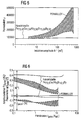
- the application-relevant magnitudes amplitude error F and phase error ⁇ are shown in FIG. 6. Due to the pronounced linearity and high permeability of the hysteresis loop both quantities are small in size and their modulation dependence is comparatively low.
- the mean phase angle ⁇ is 0.40 °.
- a linearity of the phase angle ⁇ over a current range of 0.1 to 2 A is less than 0.04 °.
- the magnetic core M had excellent aging resistance up to 150 ° C.
- FIG. 8 shows the outstandingly small temperature dependence of the magnetic core M produced from said nanocrystalline alloy, with the set permeability level of around 80000 being particularly pronounced.
Claims (17)
- Noyau magnétique pour un transformateur de courant,- réalisé à partir d'un ruban (B) enroulé en alliage ferromagnétique dont 50 % du volume sont occupés par des particules cristallines fines avec une granulométrie moyenne de 100 nm ou moins (alliage nanocristallin),- présentant une perméabilité supérieure à 12000 et inférieure à 300000,- présentant une magnétostriction de saturation dont le montant est inférieur à 1 ppm,- pour l'essentiel exempt de contrainte mécanique,- avec un axe d'anisotropie (A) le long duquel la magnétisation du noyau magnétique (M) s'oriente particulièrement facilement et qui est perpendiculaire à un plan dans lequel s'étend une ligne médiane du ruban (B), l'alliage présentant une composition pour l'essentiel selon la formuledans laquelle M est au moins l'un des éléments V, Nb, Ta, Ti, Mo, W, Zr et Hf, a, b, c, d, e, f sont indiqués en % d'atomes, et a, b, c, d, e et f remplissent les conditions suivantes :
FeaCObCUcSIdBeMf
0,5 ≤ c ≤ 2 ; 6,5 ≤ d ≤ 18 ; 5 ≤ e ≤ 14 ; 1 ≤ f ≤ 6 ; avec d + e > 18 et 0 ≤ b ≤ 15,
a + b + c + d + e + F étant = 100,
caractérisé en ce que
le ruban (B) présente une rugosité Ra (eff.) inférieure à 7 %. - Noyau magnétique selon la revendication 1,
caractérisé en ce que
a, b, c, d, e et f remplissent les conditions suivantes :
c = 1 ; 14 ≤ d ≤ 17 ; 5 ≤ e ≤ 14 ; 2 ≤ f ≤ 4 ; 0 ≤ b ≤ 0,5 ; avec 22 < d + e ≤ 24. - Noyau magnétique selon la revendication 2,
caractérisé en ce que
le montant de la magnétostriction de saturation est inférieur à 0,2 ppm. - Noyau magnétique selon l'une quelconque des revendications 1 à 3,
caractérisé en ce que
le noyau magnétique (M) présente une magnétisation de saturation Bs de 1,1 à 1,4 T. - Noyau magnétique selon l'une quelconque des revendications 1 à 4,
caractérisé en ce que
le ruban (B) est muni au moins sur une surface d'une couche (S) électriquement isolante. - Noyau magnétique selon la revendication 5,
caractérisé en ce qu'
une couche en oxyde de magnésium est prévue comme couche (S) électriquement isolante. - Noyau magnétique selon la revendication 6,
caractérisé en ce que
la couche (S) électriquement isolante présente une épaisseur (D) de 25 nm ≤ D ≤ 3 ≤ µm. - Noyau magnétique selon l'une quelconque des revendications 1 à 7,
caractérisé en ce qu'
il présente la forme d'un noyau annulaire, d'un noyau ovale ou d'un noyau rectangulaire fermé sans entrefer. - Noyau magnétique selon l'une quelconque des revendications 1 à 8,
caractérisé en ce que
le rapport entre son tenseur de contraintes mécanique élastique multiplié par la magnétostriction de saturation par rapport à son anisotropie uniaxiale est inférieur à 0,5. - Transformateur de courant pour courant alternatif comprenant un noyau magnétique selon l'une quelconque des revendications 1 à 9, qui outre le noyau magnétique (M) comme noyau de transformateur comprend au moins un bobinage primaire et au moins un bobinage secondaire qui est monté parallèlement à une résistance de charge et ferme le circuit de courant secondaire à faible résistance.
- Transformateur de courant selon la revendication 10,
caractérisé en ce que
le bobinage secondaire présente un nombre de spires Nsec ≤ 2200, le bobinage primaire présente un nombre de spires Nprim = 3 et le transformateur de courant est conçu pour un courant primaire Iprim ≤ 20 A. - Procédé de fabrication d'un noyau magnétique selon l'une quelconque des revendications 1 à 11, dans lequel- après la fabrication et l'enroulement du ruban (B) le noyau magnétique (M) est chauffé à une température cible comprise entre 450°C et 600°C pour former le noyau magnétique (M),- le noyau magnétique (M) est exposé pendant 0,1 à 8 heures à des températures entre 260°C et 590°C à une température de l'alliage inférieure à la température Curie,à un champ magnétique supérieur à 100 A/cm qui s'étend parallèlement à l'axe d'anisotropie (A) à former du noyau magnétique (M).
- Procédé selon la revendication 12, dans lequel- le chauffage à la température cible s'effectue à un taux entre 0,5 à 15 K/min,- le noyau magnétique (M) est maintenu à la température cible entre 4 minutes et 8 heures.
- Procédé selon l'une quelconque des revendications 12 ou 13, dans lequel- avant l'enroulement, le ruban (B) est muni d'une couche (S) électriquement isolante sur au moins l'une de ses deux surfaces.
- Procédé selon l'une quelconque des revendications 12 à 14, dans lequel- avant le chauffage à la température cible, le noyau magnétique (M) est soumis à une isolation par immersion pour ainsi munir le ruban (B) d'une couche (S) électriquement isolante.
- Procédé selon l'une quelconque des revendications 12 à 15, dans lequel- au moins pendant le traitement dans le champ magnétique, plusieurs noyaux magnétiques (M) identiques sont superposés côté frontal de sorte qu'une hauteur de pile est le multiple du diamètre extérieur du noyau magnétique (M).
- Procédé selon l'une quelconque des revendications 12 à 16, dans lequel- le noyau magnétique (M) est refroidi à la température ambiante à des vitesses de 0,1 à 5 K/min.
Applications Claiming Priority (3)
| Application Number | Priority Date | Filing Date | Title |
|---|---|---|---|
| DE19852424 | 1998-11-13 | ||
| DE19852424 | 1998-11-13 | ||
| PCT/DE1999/003631 WO2000030132A1 (fr) | 1998-11-13 | 1999-11-15 | Noyau magnetique destine a etre utilise dans un transformateur d'intensite, procede de fabrication d'un noyau magnetique et transformateur d'intensite equipe d'un tel noyau |
Publications (2)
| Publication Number | Publication Date |
|---|---|
| EP1131830A1 EP1131830A1 (fr) | 2001-09-12 |
| EP1131830B1 true EP1131830B1 (fr) | 2006-05-10 |
Family
ID=7887721
Family Applications (1)
| Application Number | Title | Priority Date | Filing Date |
|---|---|---|---|
| EP99963241A Expired - Lifetime EP1131830B1 (fr) | 1998-11-13 | 1999-11-15 | Noyau magnetique destine a etre utilise dans un transformateur d'intensite, procede de fabrication d'un noyau magnetique et transformateur d'intensite equipe d'un tel noyau |
Country Status (8)
| Country | Link |
|---|---|
| US (1) | US6507262B1 (fr) |
| EP (1) | EP1131830B1 (fr) |
| JP (1) | JP2002530854A (fr) |
| KR (1) | KR100606515B1 (fr) |
| AT (1) | ATE326056T1 (fr) |
| DE (1) | DE59913420D1 (fr) |
| ES (1) | ES2264277T3 (fr) |
| WO (1) | WO2000030132A1 (fr) |
Cited By (1)
| Publication number | Priority date | Publication date | Assignee | Title |
|---|---|---|---|---|
| DE102008051561B4 (de) * | 2008-10-14 | 2013-06-20 | Vacuumschmelze Gmbh & Co. Kg | Verfahren zum Herstellen einer Stromerfassungseinrichtung |
Families Citing this family (31)
| Publication number | Priority date | Publication date | Assignee | Title |
|---|---|---|---|---|
| US6559808B1 (en) * | 1998-03-03 | 2003-05-06 | Vacuumschmelze Gmbh | Low-pass filter for a diplexer |
| WO2002003082A1 (fr) * | 2000-07-06 | 2002-01-10 | Infineon Technologies Ag | Detecteur de courant et son utilisation |
| DE10045705A1 (de) * | 2000-09-15 | 2002-04-04 | Vacuumschmelze Gmbh & Co Kg | Magnetkern für einen Transduktorregler und Verwendung von Transduktorreglern sowie Verfahren zur Herstellung von Magnetkernen für Transduktorregler |
| DE10134056B8 (de) * | 2001-07-13 | 2014-05-28 | Vacuumschmelze Gmbh & Co. Kg | Verfahren zur Herstellung von nanokristallinen Magnetkernen sowie Vorrichtung zur Durchführung des Verfahrens |
| US6930581B2 (en) | 2002-02-08 | 2005-08-16 | Metglas, Inc. | Current transformer having an amorphous fe-based core |
| US7048809B2 (en) * | 2003-01-21 | 2006-05-23 | Metglas, Inc. | Magnetic implement having a linear BH loop |
| WO2004088681A2 (fr) * | 2003-04-02 | 2004-10-14 | Vacuumschmelze Gmbh & Co. Kg | Noyau magnetique, procede de realisation associe, utilisation d'un noyau magnetique de ce type notamment dans des transformateurs de courant et dans des bobines de choc a compensation de courant, alliages et bandes pour realiser un tel noyau magnetique |
| GB2407214A (en) * | 2003-10-14 | 2005-04-20 | Magtech A S | Variable inductor |
| DE102004024337A1 (de) * | 2004-05-17 | 2005-12-22 | Vacuumschmelze Gmbh & Co. Kg | Verfahren zur Herstellung nanokristalliner Stromwandlerkerne, nach diesem Verfahren hergestellte Magnetkerne sowie Stromwandler mit denselben |
| KR100621433B1 (ko) * | 2004-07-09 | 2006-09-19 | (주) 아모센스 | 자성코어를 갖는 적산전력계 |
| FR2877486B1 (fr) | 2004-10-29 | 2007-03-30 | Imphy Alloys Sa | Tore nanocristallin pour capteur de courant, compteurs d'energie a simple et a double etage et sondes de courant les incorporant |
| CN101080788A (zh) | 2004-12-17 | 2007-11-28 | 日立金属株式会社 | 电流互感器用磁芯、电流互感器及瓦时计 |
| CN1316521C (zh) * | 2005-06-23 | 2007-05-16 | 安泰科技股份有限公司 | 抗直流分量电流互感器磁芯及其制造方法和用途 |
| DE102005034486A1 (de) | 2005-07-20 | 2007-02-01 | Vacuumschmelze Gmbh & Co. Kg | Verfahren zur Herstellung eines weichmagnetischen Kerns für Generatoren sowie Generator mit einem derartigen Kern |
| JP2007299838A (ja) | 2006-04-28 | 2007-11-15 | Hitachi Metals Ltd | カレントトランス用磁心、カレントトランスならびに電力量計 |
| US20070273467A1 (en) * | 2006-05-23 | 2007-11-29 | Jorg Petzold | Magnet Core, Methods For Its Production And Residual Current Device |
| DE502007000329D1 (de) * | 2006-10-30 | 2009-02-05 | Vacuumschmelze Gmbh & Co Kg | Weichmagnetische Legierung auf Eisen-Kobalt-Basis sowie Verfahren zu deren Herstellung |
| DE102007017338A1 (de) * | 2007-02-13 | 2008-08-14 | Patent-Treuhand-Gesellschaft für elektrische Glühlampen mbH | Zündtransformator für eine Entladungslampe |
| US9057115B2 (en) * | 2007-07-27 | 2015-06-16 | Vacuumschmelze Gmbh & Co. Kg | Soft magnetic iron-cobalt-based alloy and process for manufacturing it |
| US8012270B2 (en) | 2007-07-27 | 2011-09-06 | Vacuumschmelze Gmbh & Co. Kg | Soft magnetic iron/cobalt/chromium-based alloy and process for manufacturing it |
| CN101685705B (zh) * | 2008-09-24 | 2013-11-13 | 零八一电子集团四川力源电子有限公司 | 双保护盒对扣型铁基非晶态合金带磁芯 |
| DE102010004223B4 (de) | 2010-01-08 | 2013-12-05 | Vacuumschmelze Gmbh & Co. Kg | Verfahren zum Herstellen einer Stromerfassungseinrichtung |
| WO2012064871A2 (fr) * | 2010-11-09 | 2012-05-18 | California Institute Of Technology | Noyaux ferromagnétiques d'alliages métalliques ferromagnétiques amorphes et dispositifs électroniques les possédant |
| DE102010060740A1 (de) * | 2010-11-23 | 2012-05-24 | Vacuumschmelze Gmbh & Co. Kg | Weichmagnetisches Metallband für elektromechanische Bauelemente |
| JP5886024B2 (ja) * | 2011-12-19 | 2016-03-16 | 株式会社東芝 | 磁気共鳴イメージング装置 |
| US10079619B2 (en) | 2013-11-26 | 2018-09-18 | Schneider Electric USA, Inc. | Wireless batteryless data processing unit |
| US20170092412A1 (en) * | 2015-09-26 | 2017-03-30 | Mathew J. Manusharow | Package integrated power inductors using lithographically defined vias |
| US10163557B2 (en) | 2015-12-17 | 2018-12-25 | Intel Corporation | Helical plated through-hole package inductor |
| ES2581127B2 (es) * | 2016-04-13 | 2017-05-04 | Universidad Complutense De Madrid | Etiqueta, sistema y método para la detección de objetos a larga distancia |
| RU2716282C1 (ru) * | 2018-12-29 | 2020-03-11 | Общество С Ограниченной Ответственностью "Крокус Наноэлектроника" (Ооо "Крокус Наноэлектроника") | Тонкопленочный тороидальный сердечник с анизотропией формы, катушка индуктивности и трансформатор, его содержащие |
| DE102019105215A1 (de) | 2019-03-01 | 2020-09-03 | Vacuumschmelze Gmbh & Co. Kg | Legierung und Verfahren zur Herstellung eines Magnetkerns |
Family Cites Families (12)
| Publication number | Priority date | Publication date | Assignee | Title |
|---|---|---|---|---|
| US4451876A (en) * | 1981-06-19 | 1984-05-29 | Hitachi Metals, Ltd. | Switching regulator |
| JPS6039160B2 (ja) * | 1982-07-22 | 1985-09-04 | 新日本製鐵株式会社 | 絶縁性、耐食性の優れた磁性アモルフアス合金材料 |
| JPH0610105A (ja) * | 1986-12-15 | 1994-01-18 | Hitachi Metals Ltd | Fe基軟磁性合金 |
| JPH0610104A (ja) * | 1986-12-15 | 1994-01-18 | Hitachi Metals Ltd | Fe基軟磁性合金 |
| US4881989A (en) * | 1986-12-15 | 1989-11-21 | Hitachi Metals, Ltd. | Fe-base soft magnetic alloy and method of producing same |
| JPS6479342A (en) * | 1986-12-15 | 1989-03-24 | Hitachi Metals Ltd | Fe-base soft magnetic alloy and its production |
| JPH0711396A (ja) * | 1986-12-15 | 1995-01-13 | Hitachi Metals Ltd | Fe基軟磁性合金 |
| JPH05222493A (ja) * | 1992-02-13 | 1993-08-31 | Nippon Steel Corp | Fe系高透磁率非晶質合金 |
| DE4210748C1 (de) | 1992-04-01 | 1993-12-16 | Vacuumschmelze Gmbh | Stromwandler für pulsstromsensitive Fehlerstromschutzschalter, Fehlerstromschutzschalter mit einem solchen Stromwandler, und Verfahren zur Wärmebehandlung des Eisenlegierungsbandes für dessen Magnetkern |
| EP0637038B1 (fr) * | 1993-07-30 | 1998-03-11 | Hitachi Metals, Ltd. | Noyau magnétique pour transformateur d'impulsions et transformateur d'impulsions de sela |
| JPH09143640A (ja) * | 1995-11-21 | 1997-06-03 | Kawasaki Steel Corp | 電力トランス鉄心用の広幅非晶質合金薄帯 |
| FR2755292B1 (fr) * | 1996-10-25 | 1998-11-20 | Mecagis | Procede de fabrication d'un noyau magnetique en materiau magnetique doux nanocristallin |
-
1999
- 1999-11-15 KR KR1020017006033A patent/KR100606515B1/ko active IP Right Grant
- 1999-11-15 DE DE59913420T patent/DE59913420D1/de not_active Expired - Lifetime
- 1999-11-15 ES ES99963241T patent/ES2264277T3/es not_active Expired - Lifetime
- 1999-11-15 JP JP2000583053A patent/JP2002530854A/ja active Pending
- 1999-11-15 WO PCT/DE1999/003631 patent/WO2000030132A1/fr active IP Right Grant
- 1999-11-15 AT AT99963241T patent/ATE326056T1/de not_active IP Right Cessation
- 1999-11-15 US US09/831,800 patent/US6507262B1/en not_active Expired - Lifetime
- 1999-11-15 EP EP99963241A patent/EP1131830B1/fr not_active Expired - Lifetime
Cited By (1)
| Publication number | Priority date | Publication date | Assignee | Title |
|---|---|---|---|---|
| DE102008051561B4 (de) * | 2008-10-14 | 2013-06-20 | Vacuumschmelze Gmbh & Co. Kg | Verfahren zum Herstellen einer Stromerfassungseinrichtung |
Also Published As
| Publication number | Publication date |
|---|---|
| US6507262B1 (en) | 2003-01-14 |
| WO2000030132A1 (fr) | 2000-05-25 |
| KR20010080443A (ko) | 2001-08-22 |
| JP2002530854A (ja) | 2002-09-17 |
| DE59913420D1 (de) | 2006-06-14 |
| KR100606515B1 (ko) | 2006-07-31 |
| EP1131830A1 (fr) | 2001-09-12 |
| ATE326056T1 (de) | 2006-06-15 |
| ES2264277T3 (es) | 2006-12-16 |
Similar Documents
| Publication | Publication Date | Title |
|---|---|---|
| EP1131830B1 (fr) | Noyau magnetique destine a etre utilise dans un transformateur d'intensite, procede de fabrication d'un noyau magnetique et transformateur d'intensite equipe d'un tel noyau | |
| EP1114429B1 (fr) | Transformateur de courant a tolerance vis-a-vis du courant continu | |
| DE3001889C2 (de) | Verfahren zur Herstellung einer magnetischen glasartigen Legierungsfolie | |
| DE2708151C2 (de) | Verwendung glasartiger Legierungen für Netztransformatoren oder Signalwandler | |
| EP1609159B1 (fr) | Noyau magnetique, procede de realisation associe, utilisation d'un noyau magnetique de ce type notamment dans des transformateurs de courant et dans des bobines de choc a compensation de courant, alliages et bandes pour realiser un tel noyau magnetique | |
| EP1747566B1 (fr) | Noyau de transformateur de courant et procede de production d'un noyau de transformateur de courant | |
| EP1317758B1 (fr) | Transducteur magnetique a demi-periode avec noyau magnetique, utilisation de transducteurs magnetiques a demi-periode, ainsi que procede de fabrication de noyaux magnetiques pour transducteurs magnetiques a demi-periode | |
| DE2835389A1 (de) | Magnetische legierung | |
| DE202005022087U1 (de) | Nanokristalliner Kern für Stromsensoren, ein- und zweistufige Energiezähler und diese integrierende Stromsonden | |
| DE3737266C2 (de) | Weichmagnetischer Dünnfilm | |
| EP1129459B1 (fr) | Utilisation d'un noyau magnetique pour un transformateur d'intensite, procede de fabrication d'un noyau magnetique et transformateur d'intensite equipe d'un tel noyau | |
| US6432226B2 (en) | Magnetic glassy alloys for high frequency applications | |
| US5192375A (en) | Fe-based soft magnetic alloy | |
| DE19739959C2 (de) | Hartmagnetisches Material | |
| EP0084138B1 (fr) | Alliages métalliques ayant une structure de verre, une magnétostriction de presque zéro et une grande stabilité magnétique et thermique | |
| DE3619659A1 (de) | Amorphe legierung auf fe-basis | |
| JP2919886B2 (ja) | Fe基軟磁性合金 | |
| EP0329704B1 (fr) | Alliages metalliques vitreux magnetostrictifs proches de zero pour applications haute frequence | |
| DE102018131481A1 (de) | Massive amorphe legierung und verfahren zur herstellung einer solchen legierung |
Legal Events
| Date | Code | Title | Description |
|---|---|---|---|
| PUAI | Public reference made under article 153(3) epc to a published international application that has entered the european phase |
Free format text: ORIGINAL CODE: 0009012 |
|
| 17P | Request for examination filed |
Effective date: 20010405 |
|
| AK | Designated contracting states |
Kind code of ref document: A1 Designated state(s): AT BE CH CY DE DK ES FI FR GB GR IE IT LI LU MC NL PT SE |
|
| 17Q | First examination report despatched |
Effective date: 20030903 |
|
| GRAP | Despatch of communication of intention to grant a patent |
Free format text: ORIGINAL CODE: EPIDOSNIGR1 |
|
| GRAS | Grant fee paid |
Free format text: ORIGINAL CODE: EPIDOSNIGR3 |
|
| GRAA | (expected) grant |
Free format text: ORIGINAL CODE: 0009210 |
|
| AK | Designated contracting states |
Kind code of ref document: B1 Designated state(s): AT BE CH CY DE DK ES FI FR GB GR IE IT LI LU MC NL PT SE |
|
| PG25 | Lapsed in a contracting state [announced via postgrant information from national office to epo] |
Ref country code: NL Free format text: LAPSE BECAUSE OF FAILURE TO SUBMIT A TRANSLATION OF THE DESCRIPTION OR TO PAY THE FEE WITHIN THE PRESCRIBED TIME-LIMIT Effective date: 20060510 Ref country code: IT Free format text: LAPSE BECAUSE OF FAILURE TO SUBMIT A TRANSLATION OF THE DESCRIPTION OR TO PAY THE FEE WITHIN THE PRESCRIBED TIME-LIMIT;WARNING: LAPSES OF ITALIAN PATENTS WITH EFFECTIVE DATE BEFORE 2007 MAY HAVE OCCURRED AT ANY TIME BEFORE 2007. THE CORRECT EFFECTIVE DATE MAY BE DIFFERENT FROM THE ONE RECORDED. Effective date: 20060510 Ref country code: IE Free format text: LAPSE BECAUSE OF FAILURE TO SUBMIT A TRANSLATION OF THE DESCRIPTION OR TO PAY THE FEE WITHIN THE PRESCRIBED TIME-LIMIT Effective date: 20060510 Ref country code: GB Free format text: LAPSE BECAUSE OF FAILURE TO SUBMIT A TRANSLATION OF THE DESCRIPTION OR TO PAY THE FEE WITHIN THE PRESCRIBED TIME-LIMIT Effective date: 20060510 |
|
| REG | Reference to a national code |
Ref country code: GB Ref legal event code: FG4D Free format text: NOT ENGLISH |
|
| REG | Reference to a national code |
Ref country code: CH Ref legal event code: EP |
|
| REF | Corresponds to: |
Ref document number: 59913420 Country of ref document: DE Date of ref document: 20060614 Kind code of ref document: P |
|
| REG | Reference to a national code |
Ref country code: IE Ref legal event code: FG4D Free format text: LANGUAGE OF EP DOCUMENT: GERMAN |
|
| REG | Reference to a national code |
Ref country code: CH Ref legal event code: NV Representative=s name: R. A. EGLI & CO. PATENTANWAELTE |
|
| PG25 | Lapsed in a contracting state [announced via postgrant information from national office to epo] |
Ref country code: DK Free format text: LAPSE BECAUSE OF FAILURE TO SUBMIT A TRANSLATION OF THE DESCRIPTION OR TO PAY THE FEE WITHIN THE PRESCRIBED TIME-LIMIT Effective date: 20060810 |
|
| REG | Reference to a national code |
Ref country code: SE Ref legal event code: TRGR |
|
| PG25 | Lapsed in a contracting state [announced via postgrant information from national office to epo] |
Ref country code: PT Free format text: LAPSE BECAUSE OF FAILURE TO SUBMIT A TRANSLATION OF THE DESCRIPTION OR TO PAY THE FEE WITHIN THE PRESCRIBED TIME-LIMIT Effective date: 20061010 |
|
| NLV1 | Nl: lapsed or annulled due to failure to fulfill the requirements of art. 29p and 29m of the patents act | ||
| PG25 | Lapsed in a contracting state [announced via postgrant information from national office to epo] |
Ref country code: MC Free format text: LAPSE BECAUSE OF NON-PAYMENT OF DUE FEES Effective date: 20061130 Ref country code: BE Free format text: LAPSE BECAUSE OF NON-PAYMENT OF DUE FEES Effective date: 20061130 |
|
| ET | Fr: translation filed | ||
| GBV | Gb: ep patent (uk) treated as always having been void in accordance with gb section 77(7)/1977 [no translation filed] |
Effective date: 20060510 |
|
| REG | Reference to a national code |
Ref country code: ES Ref legal event code: FG2A Ref document number: 2264277 Country of ref document: ES Kind code of ref document: T3 |
|
| REG | Reference to a national code |
Ref country code: IE Ref legal event code: FD4D |
|
| PLBE | No opposition filed within time limit |
Free format text: ORIGINAL CODE: 0009261 |
|
| STAA | Information on the status of an ep patent application or granted ep patent |
Free format text: STATUS: NO OPPOSITION FILED WITHIN TIME LIMIT |
|
| 26N | No opposition filed |
Effective date: 20070213 |
|
| BERE | Be: lapsed |
Owner name: VACUUMSCHMELZE G.M.B.H. Effective date: 20061130 |
|
| PG25 | Lapsed in a contracting state [announced via postgrant information from national office to epo] |
Ref country code: AT Free format text: LAPSE BECAUSE OF NON-PAYMENT OF DUE FEES Effective date: 20061115 |
|
| PG25 | Lapsed in a contracting state [announced via postgrant information from national office to epo] |
Ref country code: GR Free format text: LAPSE BECAUSE OF FAILURE TO SUBMIT A TRANSLATION OF THE DESCRIPTION OR TO PAY THE FEE WITHIN THE PRESCRIBED TIME-LIMIT Effective date: 20060811 |
|
| PG25 | Lapsed in a contracting state [announced via postgrant information from national office to epo] |
Ref country code: LU Free format text: LAPSE BECAUSE OF NON-PAYMENT OF DUE FEES Effective date: 20061115 |
|
| PG25 | Lapsed in a contracting state [announced via postgrant information from national office to epo] |
Ref country code: CY Free format text: LAPSE BECAUSE OF FAILURE TO SUBMIT A TRANSLATION OF THE DESCRIPTION OR TO PAY THE FEE WITHIN THE PRESCRIBED TIME-LIMIT Effective date: 20060510 |
|
| PGFP | Annual fee paid to national office [announced via postgrant information from national office to epo] |
Ref country code: CH Payment date: 20141120 Year of fee payment: 16 Ref country code: FI Payment date: 20141119 Year of fee payment: 16 Ref country code: SE Payment date: 20141120 Year of fee payment: 16 |
|
| REG | Reference to a national code |
Ref country code: FR Ref legal event code: PLFP Year of fee payment: 17 |
|
| REG | Reference to a national code |
Ref country code: CH Ref legal event code: PL |
|
| PG25 | Lapsed in a contracting state [announced via postgrant information from national office to epo] |
Ref country code: LI Free format text: LAPSE BECAUSE OF NON-PAYMENT OF DUE FEES Effective date: 20151130 Ref country code: CH Free format text: LAPSE BECAUSE OF NON-PAYMENT OF DUE FEES Effective date: 20151130 |
|
| PG25 | Lapsed in a contracting state [announced via postgrant information from national office to epo] |
Ref country code: SE Free format text: LAPSE BECAUSE OF NON-PAYMENT OF DUE FEES Effective date: 20151116 |
|
| REG | Reference to a national code |
Ref country code: FR Ref legal event code: PLFP Year of fee payment: 18 |
|
| PG25 | Lapsed in a contracting state [announced via postgrant information from national office to epo] |
Ref country code: FI Free format text: LAPSE BECAUSE OF NON-PAYMENT OF DUE FEES Effective date: 20151115 |
|
| REG | Reference to a national code |
Ref country code: FR Ref legal event code: PLFP Year of fee payment: 19 |
|
| PGFP | Annual fee paid to national office [announced via postgrant information from national office to epo] |
Ref country code: FR Payment date: 20171129 Year of fee payment: 19 |
|
| PGFP | Annual fee paid to national office [announced via postgrant information from national office to epo] |
Ref country code: ES Payment date: 20171222 Year of fee payment: 19 Ref country code: IT Payment date: 20171122 Year of fee payment: 19 |
|
| PGFP | Annual fee paid to national office [announced via postgrant information from national office to epo] |
Ref country code: DE Payment date: 20190131 Year of fee payment: 20 |
|
| PG25 | Lapsed in a contracting state [announced via postgrant information from national office to epo] |
Ref country code: FR Free format text: LAPSE BECAUSE OF NON-PAYMENT OF DUE FEES Effective date: 20181130 Ref country code: IT Free format text: LAPSE BECAUSE OF NON-PAYMENT OF DUE FEES Effective date: 20181115 |
|
| REG | Reference to a national code |
Ref country code: DE Ref legal event code: R071 Ref document number: 59913420 Country of ref document: DE |
|
| REG | Reference to a national code |
Ref country code: ES Ref legal event code: FD2A Effective date: 20200103 |
|
| PG25 | Lapsed in a contracting state [announced via postgrant information from national office to epo] |
Ref country code: ES Free format text: LAPSE BECAUSE OF NON-PAYMENT OF DUE FEES Effective date: 20181116 |