EP1131830B1 - Magnetic core that is suitable for use in a current transformer, method for the production of a magnetic core and current transformer with a magnetic core - Google Patents
Magnetic core that is suitable for use in a current transformer, method for the production of a magnetic core and current transformer with a magnetic core Download PDFInfo
- Publication number
- EP1131830B1 EP1131830B1 EP99963241A EP99963241A EP1131830B1 EP 1131830 B1 EP1131830 B1 EP 1131830B1 EP 99963241 A EP99963241 A EP 99963241A EP 99963241 A EP99963241 A EP 99963241A EP 1131830 B1 EP1131830 B1 EP 1131830B1
- Authority
- EP
- European Patent Office
- Prior art keywords
- magnetic core
- current transformer
- magnetic
- strip
- alloy
- Prior art date
- Legal status (The legal status is an assumption and is not a legal conclusion. Google has not performed a legal analysis and makes no representation as to the accuracy of the status listed.)
- Expired - Lifetime
Links
Images


Classifications
-
- H—ELECTRICITY
- H01—ELECTRIC ELEMENTS
- H01F—MAGNETS; INDUCTANCES; TRANSFORMERS; SELECTION OF MATERIALS FOR THEIR MAGNETIC PROPERTIES
- H01F1/00—Magnets or magnetic bodies characterised by the magnetic materials therefor; Selection of materials for their magnetic properties
- H01F1/01—Magnets or magnetic bodies characterised by the magnetic materials therefor; Selection of materials for their magnetic properties of inorganic materials
- H01F1/03—Magnets or magnetic bodies characterised by the magnetic materials therefor; Selection of materials for their magnetic properties of inorganic materials characterised by their coercivity
- H01F1/12—Magnets or magnetic bodies characterised by the magnetic materials therefor; Selection of materials for their magnetic properties of inorganic materials characterised by their coercivity of soft-magnetic materials
- H01F1/14—Magnets or magnetic bodies characterised by the magnetic materials therefor; Selection of materials for their magnetic properties of inorganic materials characterised by their coercivity of soft-magnetic materials metals or alloys
- H01F1/147—Alloys characterised by their composition
- H01F1/153—Amorphous metallic alloys, e.g. glassy metals
- H01F1/15308—Amorphous metallic alloys, e.g. glassy metals based on Fe/Ni
-
- H—ELECTRICITY
- H01—ELECTRIC ELEMENTS
- H01F—MAGNETS; INDUCTANCES; TRANSFORMERS; SELECTION OF MATERIALS FOR THEIR MAGNETIC PROPERTIES
- H01F1/00—Magnets or magnetic bodies characterised by the magnetic materials therefor; Selection of materials for their magnetic properties
- H01F1/01—Magnets or magnetic bodies characterised by the magnetic materials therefor; Selection of materials for their magnetic properties of inorganic materials
- H01F1/03—Magnets or magnetic bodies characterised by the magnetic materials therefor; Selection of materials for their magnetic properties of inorganic materials characterised by their coercivity
- H01F1/12—Magnets or magnetic bodies characterised by the magnetic materials therefor; Selection of materials for their magnetic properties of inorganic materials characterised by their coercivity of soft-magnetic materials
- H01F1/14—Magnets or magnetic bodies characterised by the magnetic materials therefor; Selection of materials for their magnetic properties of inorganic materials characterised by their coercivity of soft-magnetic materials metals or alloys
- H01F1/147—Alloys characterised by their composition
- H01F1/153—Amorphous metallic alloys, e.g. glassy metals
- H01F1/15333—Amorphous metallic alloys, e.g. glassy metals containing nanocrystallites, e.g. obtained by annealing
-
- H—ELECTRICITY
- H01—ELECTRIC ELEMENTS
- H01F—MAGNETS; INDUCTANCES; TRANSFORMERS; SELECTION OF MATERIALS FOR THEIR MAGNETIC PROPERTIES
- H01F38/00—Adaptations of transformers or inductances for specific applications or functions
- H01F38/20—Instruments transformers
- H01F38/22—Instruments transformers for single phase ac
- H01F38/28—Current transformers
-
- B—PERFORMING OPERATIONS; TRANSPORTING
- B82—NANOTECHNOLOGY
- B82Y—SPECIFIC USES OR APPLICATIONS OF NANOSTRUCTURES; MEASUREMENT OR ANALYSIS OF NANOSTRUCTURES; MANUFACTURE OR TREATMENT OF NANOSTRUCTURES
- B82Y30/00—Nanotechnology for materials or surface science, e.g. nanocomposites
Landscapes
- Engineering & Computer Science (AREA)
- Power Engineering (AREA)
- Chemical & Material Sciences (AREA)
- Physics & Mathematics (AREA)
- Electromagnetism (AREA)
- Dispersion Chemistry (AREA)
- Crystallography & Structural Chemistry (AREA)
- Inorganic Chemistry (AREA)
- Materials Engineering (AREA)
- Soft Magnetic Materials (AREA)
- Transformers For Measuring Instruments (AREA)
Abstract
Description
Die Erfindung betrifft einen Magnetkern, der zum Einsatz in einem Stromwandler geeignet ist, ein Verfahren zur Herstellung eines solchen Magnetkerns und einen Stromwandler mit einem solchen Magnetkern.The invention relates to a magnetic core, which is suitable for use in a current transformer, a method for producing such a magnetic core and a current transformer with such a magnetic core.
Zur Erfassung des Energieverbrauchs elektrischer Geräte und Anlagen in Industrie und Haushalt werden Energiezähler eingesetzt. Das älteste dabei gebräuchliche Prinzip ist das des Ferraris-Zählers. Der Ferraris-Zähler basiert auf der Energiezählung über die Rotation einer mit einem mechanischen Zählwerk verbundenen Scheibe, die durch die strom- bzw. spannungsproportionalen Felder entsprechender Feldspulen angetrieben wird. Für die Erweiterung der Funktionsmöglichkeiten von Energiezählern wie z.B. für Mehrtarifbetrieb oder Fernablesung werden elektronische Energiezähler eingesetzt, bei denen die Strom- und Spannungserfassung über induktive Strom- und Spannungswandler erfolgt.Energy meters are used to record the energy consumption of electrical devices and plants in industry and households. The oldest common principle is that of the Ferraris counter. The Ferraris counter is based on energy counting via the rotation of a disc connected to a mechanical counter driven by the current or voltage proportional fields of corresponding field coils. For the extension of the functional possibilities of energy meters such as e.g. For multi-tariff operation or remote reading, electronic energy meters are used in which the current and voltage are detected by inductive current and voltage transformers.
Eine spezielle Anwendung, bei der eine besonders hohe Genauigkeit gefordert ist, ist die Erfassung der Energieströme im Bereich der Elektrizitätsversorgungsunternehmen. Hier müssen zum einen die von den jeweiligen Kraftwerken erzeugten und in die Hochspannungsnetze eingespeisten Energiemengen präzise bestimmt werden, zum anderen sind für die Abrechnung die wechselnden Anteile von Verbrauch oder Lieferung im Verkehr zwischen den Energieversorgungsunternehmen von großer Bedeutung. Die hierfür eingesetzten Energiezähler sind Multifunktions-Einbaugeräte, deren Eingangssignale für Strom und Spannung aus dem jeweiligen Hoch- und Mittelspannungsanlagen über Kaskaden von Strom- und Spannungswandlern abgegriffen werden und deren Ausgangssignale zur digitalen und graphischen Registrierung bzw. Anzeige sowie zu Steuerungszwecken in den Schaltwarten dienen. Dabei dienen die netzseitig ersten Wandler zur potentialgetrennten Transformation der hohen Strom- und Spannungswerte, z.B. 1 bis 100 kA und 10 bis 500 kV, auf in Schaltschränken handhabbare Werte, die zweiten transformieren diese im eigentlichen Energiezähler auf die von der Meßelektronik benötigten Signalpegel im Bereich weniger 10 bis 100 mV.One particular application requiring a high level of accuracy is the detection of energy flows in the area of electricity supply companies. Here, on the one hand, the quantities of energy generated by the respective power plants and fed into the high-voltage grids must be precisely determined; on the other hand, the changing proportions of consumption or supply in traffic between the energy supply companies are of great importance for billing. The energy meters used for this purpose are multi-functional built-in appliances, whose input signals for current and voltage from the respective high and Medium voltage systems are tapped via cascades of current and voltage transformers and their output signals are used for digital and graphical registration or display as well as for control purposes in the control rooms. In this case, the network-side first converters are used for the potential-separated transformation of the high current and voltage values,
Die Figur 1 zeigt ein Ersatzschaltbild eines solchen Stromwandlers und die Bereiche der technischen Daten, wie sie in verschiedenen Anwendungen auftreten können. Gezeigt ist hier ein Stromwandler 1. Auf einem Magnetkern 4, der aus einem nanokristallinen weichmagnetischen Band aufgebaut ist, befindet sich die Primärwicklung 2, die den zu messenden Strom Iprim führt und eine Sekundärwicklung 3, die den Meßstrom Isec führt. Der Sekundärstrom Isec stellt sich automatisch so ein, daß die Amperewindungen primär und sekundär im Idealfall gleich groß und entgegengesetzt gerichtet sind. Der Verlauf der Magnetfelder in einem solchen Stromwandler ist in der Figur 2 dargestellt, wobei Verluste im Magnetkern nicht berücksichtigt sind. Der Strom in der Sekundärwicklung 3 stellt sich dann nach dem Induktionsgesetz so ein, daß er die Ursache seiner Entstehung, nämlich die zeitliche Änderung des magnetischen Flusses im Magnetkern 4, zu hindern versucht.FIG. 1 shows an equivalent circuit diagram of such a current transformer and the areas of the technical data which can occur in different applications. Shown here is a
Im idealen Stromwandler ist daher der Sekundärstrom, multipliziert mit dem Verhältnis der Windungszahlen, negativ gleich dem Primärstrom, was durch Gleichung (1) veranschaulicht wird: 
Dieser Idealfall wird wegen der Verluste im Bürdenwiderstand 5, im Kupferwiderstand 6 der Sekundärwicklung und im Magnetkern 4 nie erreicht.This ideal case is never reached because of the losses in the
Im realen Stromwandler weist daher der Sekundärstrom gegenüber der obigen Idealisierung einen Amplitudenfehler und einen Phasenfehler auf, was durch Gleichung (2) beschrieben wird: 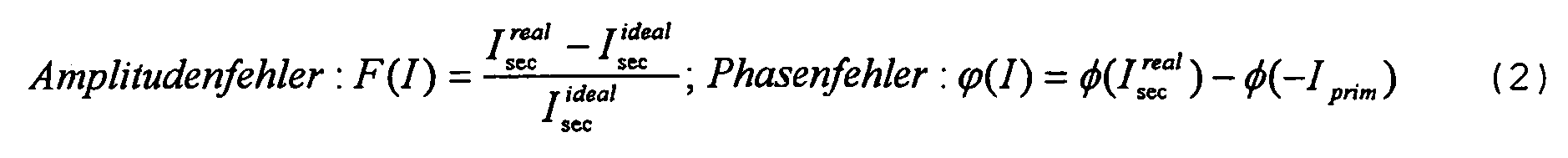
Die Ausgangssignale eines solchen Stromwandlers werden digitalisiert, multipliziert, integriert und gespeichert. Das Ergebnis ist eine elektrische Größe, die für die genannten Zwecke zur Verfügung steht.The output signals of such a current transformer are digitized, multiplied, integrated and stored. The result is an electrical quantity available for the purposes mentioned.
Die zur Energiezählung in diesen Anwendungen eingesetzten elektronischen Energiezähler arbeiten "indirekt", so daß nur rein bipolare, nullsymmetrische Wechselströme im Zähler selbst gemessen werden müssen. Dazu dienen Stromwandler, die mit Magnetkernen aus hochpermeablen Werkstoffen aufgebaut sind und zur Erreichung geringer Meßfehler über einen kleinen Phasenfehler ϕ mit sehr vielen, d.h. typischerweise 2500 und mehr, Sekundärwindungen ausgestattet sein müssen.The electronic energy meters used for energy counting in these applications work "indirectly", so that only purely bipolar, zero-symmetrical alternating currents have to be measured in the meter itself. Power converters, which are constructed with magnetic cores of highly permeable materials and serve to achieve low measurement errors by means of a small phase error φ with very many, i. typically 2500 and more, secondary windings must be equipped.
Für die Abbildung rein bipolarer Ströme sind Stromwandler bekannt, deren Magnetkerne aus hochpermeablen kristallinen Legierungen, insbesondere Nickel-Eisen-Legierungen, bestehen, die ca. 80 Gew.% Nickel enthalten und unter dem Namen "Permalloy" bekannt sind. Diese weisen einen grundsätzlich sehr niedrigen Phasenfehler ϕ auf. Sie haben dabei aber den Nachteil, daß dieser Phasenfehler ϕ stark mit dem zu messenden Strom Iprim, was gleichbedeutend mit der Aussteuerung des Wandlerkerns ist, variiert. Für eine präzise Strommessung bei wechselnden Lasten mit diesen Wandlern ist daher eine aufwendige Linearisierung im Energiezähler erforderlich.Current transformers are known for the imaging of purely bipolar currents whose magnetic cores consist of highly permeable crystalline alloys, in particular nickel-iron alloys, which contain about 80% by weight of nickel and are known under the name "permalloy". These have a basically very low phase error φ. But they have the disadvantage that this phase error φ varies greatly with the measured current I prim , which is synonymous with the modulation of the converter core. For a precise current measurement with changing loads with these converters is therefore a complex linearization in the energy meter required.
Des weiteren sind Stromwandler bekannt, die auf der Basis eisenloser Luftspulen arbeiten. Dieses Prinzip ist als sogenanntes Rogowski-Prinzip bekannt. Hierbei entfällt der Einfluss der Aussteuerung auf den Phasenfehler. Da die Anforderungen an die Störsicherheit solcher Stromwandler jedoch sehr hoch sein müssen, um eine eichfähige Energiezählung zu ermöglichen, sind diese Konstruktionen mit aufwendigen Abschirmungen gegen äußere Felder ausgestattet, was einen hohen Material- und Montageaufwand bedeutet und daher kostenintensiv ist.Furthermore, current transformers are known which operate on the basis of ironless air coils. This principle is known as the so-called Rogowski principle. This eliminates the influence of the modulation on the phase error. However, since the requirements of the noise immunity of such current transformer must be very high to allow a verifiable energy metering, these structures are equipped with elaborate shielding against external fields, which means a high material and installation costs and therefore costly.
Ferner sind Lösungen bekannt, bei denen ein mit einem Luftspalt versehener (gescherter) Ferrit-Schalenkern als Magnetkern eingesetzt wird. Diese Stromwandler verfügen über eine sehr gute Linearität, jedoch ist aufgrund der relativ niedrigen Permeabilität der Ferrite eine sehr hohe Windungszahl in Verbindung mit einem sehr großvolumigen Magnetkern erforderlich, um bei dem Stromwandler einen geringen Phasenwinkel zu erzielen. Diese auf Ferrit Schalenkernen basierenden Stromwandler weisen ferner ebenfalls eine hohe Empfindlichkeit gegenüber externen Fremdfeldern auf, so dass auch dort Abschirmmaßnahmen getroffen werden müssen. Außerdem sind bei Ferriten in der Regel die Magnetwerte stark temperaturabhängig.Furthermore, solutions are known in which a provided with an air gap (sheared) ferrite pot core is used as a magnetic core. These current transformers have very good linearity, but due to the relatively low permeability of the ferrites, a very high number of turns is required in connection with a very large magnetic core in order to achieve a low phase angle in the current transformer. Furthermore, these current transformers based on ferrite pot kernels likewise have a high sensitivity to external external fields, so that shielding measures must also be taken there. In addition, in the case of ferrites, the magnet values are generally strongly temperature-dependent.
Die EP-A-0 271 657 offenbart hierzu Wickelkerne aus amorphen magnetischen Legierungen, die in den Zusammensetzungsbereich FeaCobCucSidBeMf fallen, worin M zumindest eines der Elemente V, Nb, Ta, Ti, Mo, W, Zr und Hf ist, a, b, c, d, e, f in Atom-% angegeben sind, und wobei a, b, c, d, e und f die Bedingungen 0,5 ≤ c ≤ 2; 6,5 ≤ d ≤ 18; 5 ≤ e 14; 1 ≤ f ≤6; mit d + e > 18 und 0 ≤ b ≤ 15, wobei a + b + c + d + e + f = 100 erfüllen.EP-A-0 271 657 discloses winding cores of amorphous magnetic alloys which fall within the composition range Fe a Co b Cu c Si d B e M f , where M is at least one of the elements V, Nb, Ta, Ti, Mo, W, Zr and Hf are, a, b, c, d, e, f are in atomic%, and wherein a, b, c, d, e and f are the conditions 0.5 ≤ c ≤ 2; 6.5 ≤ d ≤ 18; 5 ≤
Der Erfindung liegt die Aufgabe zugrunde, einen Magnetkern anzugeben, der bei Einsatz in einem Stromwandler im Vergleich zum Stand der Technik eine höhere Messgenauigkeit eines zu messenden Stroms bei gleichzeitig wirtschaftlicher Ausführung und kompakter Baugröße gestattet. Ferner soll ein Verfahren zur Herstellung eines solchen Magnetkerns sowie ein Stromwandler mit einem solchen Magnetkern angegeben werden.The invention is based on the object, a magnetic core specify that when used in a current transformer in comparison to the prior art, a higher measurement accuracy of a current to be measured at the same time economic design and compact size allowed. Furthermore, a method for producing such a magnetic core and a current transformer with such a magnetic core to be specified.
Darüber hinaus soll die Temperaturabhängigkeit der Eigenschaften möglichst gering sein.In addition, the temperature dependence of the properties should be as low as possible.
Die Aufgabe wird gelöst durch einen Magnetkern, der zum Einsatz in einem Stromwandler geeignet ist, dadurch gekennzeichnet, dass er aus einem gewickelten Band aus einer ferromagnetischen Legierung besteht, bei der mindestens 50% der Legierung von feinen kristallinen Teilchen mit einer mittleren Teilchengröße von 100 nm oder weniger eingenommen wird (nanokristalline Legierung), er eine Sättigungspermeabilität aufweist, die größer als 12000, besser 20000, und kleiner als 300000, besser 350000, ist, er eine Sättigungsmagnetostriktion aufweist, deren Betrag kleiner als 1 ppm ist, er im wesentlichen frei von mechanischen Spannung ist, und er eine magnetische Anisotropieachse aufweist, entlang der sich die Magnetisierung des Magnetkerns besonders leicht ausrichtet und die senkrecht zu einer Ebene ist, in der eine Mittellinie des Bandes verläuft. Die Legierung weist eine Zusammensetzung auf, die im wesentlichen aus der Formel
FeaCobCucSidBeMf
besteht, worin M zumindest eines der Elemente V, Nb, Ta, Ti, Mo, W, Zr und Hf ist, a, b, c, d, e, f in Atom-% angegeben sind, und wobei a, b, c, d, e und f die folgenden Bedingungen erfüllen :
0,5 ≤ c ≤ 2; 6,5 ≤ d ≤ 18; 5 ≤ e 14; 1 ≤ f ≤6;
mit d + e > 18 und 0 ≤ b ≤ 15, wobei a + b + c + d + e + f = 100 sind.The object is achieved by a magnetic core which is suitable for use in a current transformer, characterized in that it consists of a wound band of a ferromagnetic alloy in which at least 50% of the alloy of fine crystalline particles having an average particle size of 100 nm or less (nanocrystalline alloy) having a saturation permeability greater than 12,000, more preferably 20,000, and less than 300,000, more preferably 350,000, has a saturation magnetostriction of which amount is less than 1 ppm, it is substantially free of is mechanical stress and has a magnetic anisotropy axis along which the magnetization of the magnetic core is particularly easy to align and which is perpendicular to a plane in which a center line of the band passes. The alloy has a composition consisting essentially of the formula
Fe a Co b Cu c Si d B e M f
where M is at least one of V, Nb, Ta, Ti, Mo, W, Zr and Hf, a, b, c, d, e, f are in atomic%, and wherein a, b, c , d, e and f satisfy the following conditions:
0.5 ≤ c ≤ 2; 6.5 ≤ d ≤ 18; 5 ≤
with d + e> 18 and 0 ≤ b ≤ 15, where a + b + c + d + e + f = 100 are.
Erfindungsgemäß wird das Band dabei so hergestellt, dass es eine kleine effektive Rauhtiefe aufweist. Dadurch lassen sich ein besonders gutes Remanenzverhältnis und damit eine besonders gute Linearität des Stromwandlers erzielen. Es hat sich gezeigt, dass 7 % als oberer Grenzwert für die effektive Rauhtiefe besonders gut ist, wobei jedoch mit abnehmender effektiver Rauhtiefe die Streuung aber auch der Betrag der Remanenz kleiner wird und damit die Stabilität der Linearität signifikant zunimmt.According to the invention, the strip is produced in such a way that it has a small effective surface roughness. As a result, a particularly good remanence ratio and thus a particularly good linearity of the current transformer can be achieved. It has been shown that 7% as the upper limit of the effective surface roughness is particularly good, but with decreasing effective surface roughness, the scattering but also the amount of remanence is smaller and thus the stability of the linearity significantly increases.
Die Rauhtiefe der Oberflächen des Bandes und auch die Banddicken sind wesentliche Einflussgrößen auf die magnetischen Eigenschaften. Maßgeblich ist die effektive Rauhtiefe. Unter der effektiven Rauhtiefe versteht man die Summe der mittleren Rauhtiefen Ra der beiden sich gegenüberliegenden Bandoberflächen dividiert durch die Banddicke. Die Figur 4 zeigt sehr anschaulich, dass sich das Remanenzverhältnis und damit die Linearität der Stromwandler durch Einstellung der Rauhtiefe einstellen lässt.The roughness of the surfaces of the strip and also the strip thicknesses are significant influencing factors on the magnetic properties. Decisive is the effective roughness. The effective roughness depth is the sum of the mean roughness depths Ra of the two mutually opposite strip surfaces divided by the strip thickness. FIG. 4 shows very clearly that the remanence ratio and thus the linearity of the current transformers can be adjusted by adjusting the roughness depth.
Die Permeabilität bezieht sich auf eine in der Ebene der Mittellinie des Bandes angelegte Feldstärke und die hierdurch hervorgerufene Induktion.The permeability refers to a field strength applied in the plane of the centerline of the ribbon and the induction thereby induced.
Es hat sich gezeigt, dass bei einem solchen Magnetkern die Abhängigkeit der Permeabilität von der Magnetisierung sehr klein ist. Die Hystereseschleife des Magnetkerns ist also sehr schmal und linear. Dies setzt ein möglichst kleines Verhältnis von Remanenzinduktion zu Sättigungsinduktion von möglichst weniger als 5 % und kleine Koerzitivfeldstärken von möglichst weniger als 10 mA/cm, besser 5 mA/cm voraus.It has been found that in such a magnetic core, the dependence of the permeability of the magnetization is very small. The hysteresis loop of the magnetic core is so very narrow and linear. This requires the smallest possible ratio of remanent induction to saturation induction of less than 5% and small coercive forces of less than 10 mA / cm, preferably 5 mA / cm.
Da die Permeabilität mit über 12.000 sehr groß ist und zudem im wesentlichen unabhängig von der Magnetisierung ist, sind der absolute Phasenfehler und der absolute Amplitudenfehler eines Stromwandlers mit einem solchen Magnetkern sehr klein. Der absolute Amplitudenfehler kann kleiner als 10/00 sein. Der absolute Phasenfehler kann kleiner als 0,1° sein.Since the permeability of more than 12,000 is very large and also substantially independent of the magnetization, the absolute phase error and the absolute amplitude error of a current transformer with such a magnetic core are very small. The absolute amplitude error can be less than 1 0 / 00th The absolute phase error can be less than 0.1 °.
Der Stromwandler weist neben dem Magnetkern mindestens eine Primärwicklung und eine Sekundärwicklung, zu der ein Bürdenwiderstand parallel geschaltet ist und der den Sekundärstromkreis niederohmig abschließt, auf.The current transformer has, in addition to the magnetic core, at least one primary winding and a secondary winding, to which a load resistor is connected in parallel and which terminates the secondary circuit in a low-impedance manner.
Es hat sich ferner gezeigt, daß die Hystereseschleife des Magnetkerns eine hohe Linearität aufweist. So betragen ein Permeabilitätsverhältnis µ15/µ4 < 1,1 und ein Permeabilitätsverhältnis µ10/µ0,5 < 1,1, wobei µ0,5, µ4, µ10 und µ15 die Permeabilitäten bei einer Feldamplitude H von 0.5, 4, 10 und 15 mA/cm sind.It has also been found that the hysteresis loop of the magnetic core has a high linearity. Thus, a permeability ratio μ 15 / μ 4 <1.1 and a permeability ratio μ 10 / μ 0.5 <1.1, where μ 0.5 , μ 4 , μ 10 and μ 15 are the permeabilities at a field amplitude H of 0.5 , 4, 10 and 15 mA / cm.
Aufgrund der guten Linearität weisen der Phasen- sowie der Amplitudenfehler im wesentlichen keine Abhängigkeit vom zu messenden Strom auf. Aufgrund der hohen Sättigungsinduktion von beispielsweise 1,2 Tesla gilt dies im Gegensatz zu anderen weichmagnetischen hochpermeablen Werkstoffen für einen weiteren Feldstärken- bzw. Induktionsbereich.Due to the good linearity, the phase and amplitude errors have essentially no dependence on the current to be measured. Due to the high saturation induction of, for example, 1.2 Tesla, this applies, in contrast to other soft-magnetic high-permeability materials, to a further field strength or induction range.
Da der absolute Phasenfehler, der absolute Amplitudenfehler und die Abhängigkeit der Fehler vom zu messenden Strom sehr klein sind, kann durch den Stromwandler eine sehr exakte Stromerfassung erfolgen.Since the absolute phase error, the absolute amplitude error and the dependence of the error on the current to be measured are very small, can be done by the current transformer very accurate current detection.
Aufgrund der nanokristallinen Struktur weist der Magnetkern eine überraschend hohe Alterungsbeständigkeit auf, die eine obere Anwendungsgrenztemperatur für den Magnetkern von über 120°C, in Einzelfällen sogar um 150°C erlaubt. Gerade dadurch eignet sich der Stromwandler mit dem Magnetkern für einen Einsatz weit oberhalb der Raumtemperatur.Due to the nanocrystalline structure of the magnetic core has a surprisingly high resistance to aging, which allows an upper application limit temperature for the magnetic core of about 120 ° C, in some cases even by 150 ° C. This makes the current transformer with the magnetic core suitable for use far above room temperature.
Die Eigenschaften des Magnetkerns sind nur schwach temperaturabhängig, wobei diese Abhängigkeit wiederum weitgehend linear verläuft.The properties of the magnetic core are only weakly temperature-dependent, with this dependence in turn being largely linear.
Der Erfindung liegt die Erkenntnis zugrunde, daß mit der Legierung der beschriebenen Zusammensetzung durch eine geeignete Wärmebehandlung ein Magnetkern mit den beschriebenen Eigenschaften erzeugt werden kann. Dabei sind sehr viele Parameter aufeinander abgestimmt, damit der Magnetkern die beschriebenen Eigenschaften aufweist.The invention is based on the finding that with the alloy of the composition described by a suitable heat treatment, a magnetic core can be produced with the properties described. In this case, many parameters are matched to each other, so that the magnetic core has the properties described.
Durch die bei der Wärmebehandlung erzeugte nanokristalline Zweiphasenstruktur werden bei gleichzeitig hoher Sättigungsinduktion und hoher thermischer Stabilität die beiden grundlegenden Voraussetzungen für gute weichmagnetische Eigenschaften erfüllt:
- 1) Eliminierung, d.h. Ausmittelung der Kristallanisotropie K1 durch die glättende Wirkung der kornübergreifenden ferromagnetischen Austauschwechselwirkung.
- 2) Weitestgehende Einstellung des Nulldurchgangs der Sättigungsmagnetostriktion λS (λS < 1ppm) durch Überlagerung der beiden Magnetostriktionsbeiträge von nanokristallinem Korn und amorpher intergranularer Restphase.
- 1) Elimination, ie evaluation of the crystal anisotropy K 1 by the smoothing effect of the grain-spanning ferromagnetic exchange interaction.
- 2) Largest setting of the zero crossing of the saturation magnetostriction λ S (λ S <1 ppm) by superposition of the two magnetostriction contributions of nanocrystalline grain and amorphous intergranular residual phase.
Da hierdurch die im Band bzw. Magnetkern verbleibenden Störanisotropien bis auf ca. 2 J/m3 oder noch weniger eliminiert werden, können bereits bei sehr kleinen uniaxialen magnetfeldinduzierten Queranisotropien hochlineare Hystereseschleifen (F-Schleifen) mit höchsten Permeabilitäten erzeugt werden.Since this eliminates the remaining in the band or magnetic core noise anisotropies up to about 2 J / m 3 or even less, even at very small uniaxial magnetic field-induced Queranisotropien highly linear Hysteresis loops (F loops) are generated with the highest permeability.
Im folgenden wird eine Wärmebehandlung, die ein Verfahren zur Herstellung eines Magnetkerns ist und ebenfalls die Aufgabe löst, beschrieben:Hereinafter, a heat treatment which is a method for manufacturing a magnetic core and also solves the problem is described.
Nach Herstellung und Wicklung des Bandes zum Magnetkern wird der Magnetkern auf eine Zieltemperatur zwischen 450°C und 600° C erhitzt. Vorzugsweise liegt die Zieltemperatur oberhalb 520°C. Dabei wird ausgehend von einem amorphem Zustand des Bandes die nanokristalline Zweiphasenstruktur ausgebildet.After making and winding the tape to the magnetic core, the magnetic core is heated to a target temperature between 450 ° C and 600 ° C. Preferably, the target temperature is above 520 ° C. In this case, starting from an amorphous state of the strip, the nanocrystalline two-phase structure is formed.
Nachdem die nanokristalline Zweiphasenstruktur ausgebildet wurde, wird zur Bildung der Anisotropieachse bei einer Temperatur unterhalb der Curie-Temperatur der Legierung ein Magnetfeld von mindestens 100 A/cm eingeschaltet, das transversal zur Richtung des gewickelten Bandes steht (Querfeld). Dieses Querfeld muß so groß sein, daß sich der Kern in Richtung der auszubildenden Anisotropieachse im Zustand seiner Sättigungsinduktion befindet. Die Curie-Temperatur ist die Temperatur, bei der eine spontane Magnetisierung der Legierung einsetzt.After the nanocrystalline two-phase structure has been formed, a magnetic field of at least 100 A / cm is activated to form the anisotropy axis at a temperature below the Curie temperature of the alloy, which is transverse to the direction of the wound strip (transverse field). This transverse field must be so large that the core is in the direction of the trainees anisotropy axis in the state of its saturation induction. The Curie temperature is the temperature at which a spontaneous magnetization of the alloy begins.
Die Zieltemperatur ist so gewählt, daß sie oberhalb der Kristallisationstemperatur der Legierung liegt. Sie wird derart an die Legierungszusammensetzung angepaßt, daß aufgrund der sich einstellenden Korngrößenverteilung und Volumenerfüllung des Korns eine möglichst gute Ausmittelung der Kristallanisotropie K1 entsteht. Gleichzeitig sollen sich die Magnetostriktionsbeiträge von nanokristallinem Korn und amorpher Restphase derartig ausgleichen, daß die resultierende Sättigungsmagnetostriktion sehr klein ist oder möglichst ganz verschwindet.The target temperature is chosen to be above the crystallization temperature of the alloy. It is adapted to the alloy composition in such a way that the best possible averaging of the crystal anisotropy K 1 is produced on the basis of the grain size distribution and volume filling of the grain. At the same time, the magnetostriction contributions of nanocrystalline grain and amorphous residual phase should balance out in such a way that the resulting saturation magnetostriction is very small or as far as possible disappears.
Gleichzeitig bewirkt das Erhitzen einen Abbau mechanischer Spannungen im Band und im gewickelten Magnetkern, so daß die Entstehung des nanokristallinen Korns im spannungsfreien Zustand stattfindet und keine spannungsinduzierten Anisotropien entstehen können.At the same time, the heating causes a reduction of mechanical stresses in the band and in the wound magnetic core, so that the formation of the nanocrystalline grain takes place in a stress-free state and no stress-induced anisotropies can arise.
Eine besonders hohe Linearität der Hystereseschleife läßt sich erzielen, wenn das Verhältnis des mechanischen elastischen Spannungstensors des Magnetkerns multipliziert mit der Sättigungsmagnetostriktion zur uniaxialen Anisotropie kleiner als 0,5 ist.A particularly high linearity of the hysteresis loop can be achieved if the ratio of the mechanical elastic stress tensor of the magnetic core multiplied by the saturation magnetostriction to uniaxial anisotropy is less than 0.5.
Die Feldstärke des senkrecht zum gewickelten Band angelegten Magnetfeldes (Querfeld) ist derart gewählt, daß es deutlich größer ist als die zum Erreichen der Sättigungsinduktion in dieser Richtung des Kerns notwendigen Feldstärke. Diese ist in der Regel größer als 100 A/cm.The field strength of the magnetic field applied perpendicular to the wound tape (transverse field) is chosen such that it is significantly greater than the field strength necessary to achieve the saturation induction in this direction of the core. This is usually greater than 100 A / cm.
Es liegt im Rahmen der Erfindung, zwei aufeinanderfolgende Wärmebehandlungen durchzuführen. Die erste Wärmebehandlung dient der Ausbildung der nanokristallinen Zweiphasenstruktur. Die zweite Wärmebehandlung kann bei einer niedrigeren Temperatur als die erste Wärmebehandlung erfolgen und dient der Ausbildung der Anisotropieachse. Alternativ wird in derselben Wärmebehandlung zunächst die nanokristalline Zweiphasenstruktur ausgebildet und anschließend die Anisotropieachse induziert.It is within the scope of the invention to carry out two successive heat treatments. The first heat treatment serves to form the nanocrystalline two-phase structure. The second heat treatment may be at a lower temperature than the first heat treatment and serves to form the anisotropy axis. Alternatively, the nanocrystalline two-phase structure is first formed in the same heat treatment, and then the anisotropy axis is induced.
Werden z.B. Permeabilitäten im unteren Bereich des angegebenen Fensters von 12000 - 300000 gefordert, kann die Erzeugung der nanokristallinen Struktur und die Ausbildung der Anisotropieachse auch gleichzeitig erfolgen. Hierzu wird der Magnetkern auf die Zieltemperatur erhitzt, dort bis zur Ausbildung der nanokristallinen Struktur gehalten und danach wieder auf Raumtemperatur abgekühlt. Je nach erforderlicher Permeabilität wird das Querfeld entweder während der gesamten Wärmebehandlung angelegt oder erst nach Erreichen der Zieltemperatur oder sogar noch später eingeschaltet.If, for example, permeabilities in the lower range of the specified window of 12,000-300,000 are required, the generation of the nanocrystalline structure and the formation of the anisotropy axis can also take place simultaneously. For this purpose, the magnetic core is heated to the target temperature, held there until the formation of the nanocrystalline structure and then cooled back to room temperature. Depending on the required permeability, the transverse field either during the entire Heat treatment applied or switched on only after reaching the target temperature or even later.
Das Erhitzen auf die Zieltemperatur erfolgt möglichst schnell. Beispielsweise erfolgt das Erhitzen auf die Zieltemperatur mit einer Rate zwischen 1 bis 15 K/min. Zur Erzielung eines inneren Temperaturausgleiches im Kern kann dabei im Temperaturbereich der einsetzenden Kristallisation eine verzögerte Aufheizrate unter 1 K/min oder sogar ein mehrminütiges Temperaturplateau eingelegt werden.The heating to the target temperature is as fast as possible. For example, heating to the target temperature occurs at a rate between 1 to 15 K / min. To achieve an internal temperature compensation in the core, a delayed heating rate of less than 1 K / min or even a temperature plateau lasting several minutes can be introduced in the temperature range of the onset of crystallization.
Der Magnetkern wird beispielsweise zwischen 4 Minuten und 8 Stunden auf der Zieltemperatur um 550 °C gehalten, um ein möglichst kleines Korn mit homogener Korngrößenverteilung und kleinen intergranularen Abständen zu erreichen. Die Temperatur wird dabei umso höher gewählt, je niedriger der Si- Gehalt in der Legierung ist. Dabei stellt beispielsweise das Einsetzen unmagnetischer Boridphasen oder das Wachsen von Oberflächenkristalliten auf dem Band eine Obergrenze für die Zieltemperatur dar.The magnetic core is kept at the target temperature around 550 ° C, for example, between 4 minutes and 8 hours in order to achieve the smallest possible grain with homogeneous particle size distribution and small intergranular distances. The temperature is chosen higher, the lower the Si content in the alloy. For example, the onset of nonmagnetic boride phases or the growth of surface crystallites on the tape is an upper limit to the target temperature.
Zur Einstellung der Anisotropieachse und damit der linearen Hystereseschleife (F-Schleife) wird der Magnetkern zwischen 0,1 und 8 Stunden unterhalb der Curie-Temperatur, z.B. zwischen 260 °C und 590 °C bei eingeschaltetem transversalem Magnetfeld gehalten. Die hierbei induzierte uniaxiale Anisotropie ist umso größer je höher die Temperatur im Querfeld gewählt wird. Das Permeabilitätsniveau verhält sich dazu reziprok, so daß bei den niedrigsten Temperaturen die höchsten Werte entstehen. Anschließend wird der Kern z.B. mit 0,1 bis 5 K/min im anliegenden Querfeld auf raumtemperaturnahe Werte von z.B. 25 °C oder z.B. 50 °C abgekühlt. Dies ist einerseits aus wirtschaftlichen Gründen vorteilhaft, andererseits kann aus Linearitätsgründen unterhalb der Curie-Temperatur nicht feldfrei abgekühlt werden kann.To set the anisotropy axis and thus the linear hysteresis loop (F-loop), the magnetic core is held between 0.1 and 8 hours below the Curie temperature, eg between 260 ° C and 590 ° C with the transverse magnetic field switched on. The uniaxial anisotropy induced in this case is greater the higher the temperature in the transverse field is chosen. The permeability level is reciprocal to the highest values at the lowest temperatures. Subsequently, the core is cooled, for example, at 0.1 to 5 K / min in the adjacent transverse field to near-room temperature values of, for example, 25 ° C. or, for example, 50 ° C. On the one hand, this is advantageous for economic reasons, on the other hand, it can not be cooled field-free for reasons of linearity below the Curie temperature.
Das Magnetfeld kann während der gesamten Wärmebehandlung eingeschaltet sein.The magnetic field can be switched on during the entire heat treatment.
Die Zusammensetzung der Legierung wird derart gewählt, daß einerseits eine möglichst gute Ausmittelung der Kristallanisotropie des nanokristallinen Korns erfolgt, andererseits aber der Nulldurchgang der Sättigungsmagnetostriktion möglichst gut getroffen wird. Gleichzeitig darf jedoch der Metalloidgehalt nicht zu hoch angesetzt werden, da hierdurch das Band versprödet und Gießbarkeit, Wickelbarkeit und Schneidbarkeit des Bandes verloren gehen. Andererseits soll jedoch die Kristallisationstemperatur möglichst hoch sein, damit z.B. während des Gießprozesses des Bandes keine Keime für Oberflächenkristallite entstehen, die für die Linearität der Schleife äußerst schädlich sind. Letzteres läßt sich in gewissen Grenzen z.B. durch erhöhte Gehalte an B und/oder Nb erreichen.The composition of the alloy is chosen such that, on the one hand, the best possible determination of the crystal anisotropy of the nanocrystalline grain takes place, but on the other hand, the zero crossing of the saturation magnetostriction is hit as well as possible. At the same time, however, the metalloid content must not be set too high, as this embrittles the tape and lost castability, windability and cuttability of the tape. On the other hand, however, the crystallization temperature should be as high as possible, e.g. during the casting process of the strip, no nuclei for surface crystallites are formed, which are extremely detrimental to the linearity of the loop. The latter can be achieved within certain limits, e.g. reach through increased levels of B and / or Nb.
Aufgrund der hohen Permeabilität kann der Stromwandler bei zugleich exakter Stromerfassung ein besonders kleines Volumen aufweisen.Due to the high permeability, the current transformer can have a particularly small volume while at the same time accurately detecting the current.
Eine weitere Verbesserung hinsichtlich der Linearität der Hystereseschleife des Magnetkerns und damit des Übertragungsverhaltens des Stromwandlers läßt sich erzielen, wenn der Magnetkern einen Magnetostriktionswert |λS| < 0,2 ppm aufweist und der Magnetkern eine nanokristalline, ferromagnetische Legierung enthält, die eine Zusammensetzung aufweist, die im wesentlichen aus der Formel
FeaCobCucSidBeMf
besteht, worin M zumindest eines der Elemente V, Nb, Ta, Ti, Mo, W, Zr und Hf ist, a, b, c, d, e, f in Atom-% angegeben sind und a, b, c, d, e und f die folgenden Bedingungen erfüllen:
c = 1; 14 ≤ d ≤ 17; 5 ≤ e ≤ 14; 2 ≤ f ≤ 4; mit 22 ≤ d + e ≤ 24 und 0 ≤ b ≤ 0.5, wobei a + b + c + d + e + f = 100 sind.A further improvement in terms of the linearity of the hysteresis loop of the magnetic core and thus the transmission behavior of the current transformer can be achieved if the magnet core has a magnetostriction value | λ S | <0.2 ppm and the magnetic core contains a nanocrystalline ferromagnetic alloy having a composition consisting essentially of the formula
Fe a Co b Cu c Si d B e M f
where M is at least one of V, Nb, Ta, Ti, Mo, W, Zr and Hf, a, b, c, d, e, f are in atomic% and a, b, c, d , e and f satisfy the following conditions:
c = 1; 14 ≤ d ≤ 17; 5 ≤ e ≤ 14; 2 ≤ f ≤ 4; with 22 ≤ d + e ≤ 24 and 0 ≤ b ≤ 0.5, where a + b + c + d + e + f = 100.
Die obengenannten Legierungssysteme zeichnen sich durch sehr lineare, ausgesprochen schmale Hystereseschleifen aus und weisen je nach dabei eingestellter uniaxialer Anisotropie Ku bei einer Feldamplitude von Ĥ = 4 mA/cm eine Permeabilität von 12000 < µ4 < 300000 auf. In Figur 3 sind Hystereseschleifen von Magnetkernen aus einigen der obengenannten Legierungssysteme gezeigt. Diese Legierungssysteme sind nahezu magnetostriktionsfrei. Die Magnetostriktion wird vorzugsweise durch eine Wärmebehandlung eingestellt, so daß lineare Hystereseschleifen mit einem aufgrund der hohen Sättigungsinduktion von BS = 1,1 bis 1,4 T weiträumig nutzbaren Induktionsbereich und einem sehr guten Frequenzgang bezüglich der Permeabilität und niedrigen Ummagnetisierungsverlusten herstellbar sind.The abovementioned alloy systems are characterized by very linear, extremely narrow hysteresis loops and, depending on the uniaxial anisotropy K u set at a field amplitude of Ĥ = 4 mA / cm, have a permeability of 12000 <μ 4 <300 000. FIG. 3 shows hysteresis loops of magnetic cores of some of the abovementioned alloy systems. These alloy systems are almost magnetostriction-free. The magnetostriction is preferably adjusted by a heat treatment, so that linear hysteresis loops can be produced with an induction range that can be used over a wide area due to the high saturation induction of B S = 1.1 to 1.4 T and a very good frequency response with respect to permeability and low core losses.
Bei dem oben erwähnten bevorzugten nanokristallinen Legierungssystem wird durch eine exakt abgeglichene Temperatur-Haltezeitfunktion ausgenutzt, daß sich bei den erfindungsgemäß eingesetzten Legierungszusammensetzungen gerade die Magnetostriktionsbeiträge von feinkristallinem Korn und amorpher Restphase ausgleichen und die erforderliche Magnetostriktionsfreiheit entsteht.In the case of the abovementioned preferred nanocrystalline alloy system, a precisely balanced temperature hold-time function makes use of the fact that the magnetostriction contributions of fine-crystalline grain and amorphous residual phase are just compensated for in the alloy compositions used according to the invention and the required magnetostriction freedom arises.
Vorzugsweise weist der Magnetkern keinen Luftspalt auf. Ein Stromwandler mit einem Magnetkern ohne Luftspalt weist eine besonders hohe Immunität gegenüber externen Fremdmagnetfeldern ohne zusätzliche Abschirmmaßnahmen auf. Der Magnetkern ist beispielsweise ein geschlossener, luftspaltloser Ringkern, Ovalkern oder Rechteckkern. Weist der Kern eine Rotationssymmetrieachse auf, so ist die Anisotropieachse parallel zur Rotationssymmetrieachse. Auf jeden Fall steht diese Anisotropieachse möglichst exakt senkrecht zur Richtung des gewickelten Bandes.Preferably, the magnetic core has no air gap. A current transformer with a magnetic core without an air gap has a particularly high immunity to external foreign magnetic fields without additional shielding measures. The magnetic core is for example a closed, air-gapless ring core, oval core or rectangular core. If the core has a rotational symmetry axis, then the anisotropy axis is parallel to the rotational symmetry axis. In any case, this anisotropy axis is as exactly perpendicular to the direction of the wound tape.
Zur Erzeugung des Magnetkerns kann das Band rund gewickelt werden und falls erforderlich mittels geeigneter Formgebungswerkzeuge während der Wärmebehandlung in die entsprechende Form gebracht werden.To produce the magnetic core, the band can be wound around and, if necessary, brought into the appropriate shape during the heat treatment by means of suitable shaping tools.
Besonders kleine Koerzitivfeldstärken und damit eine besonders gute Linearität der Hystereseschleife werden erzielt, wenn das Band zumindest an einer Oberfläche mit einer elektrisch isolierenden Schicht versehen ist. Dies bewirkt einerseits eine bessere Entspannung des Magnetkerns, andererseits lassen sich auch besonders niedrige Wirbelstromverluste erreichen.Particularly small coercive field strengths and thus a particularly good linearity of the hysteresis loop are achieved if the strip is provided with an electrically insulating layer at least on one surface. On the one hand this results in a better relaxation of the magnetic core, on the other hand, particularly low eddy current losses can be achieved.
Das Band wird beispielsweise vor dem Wickeln an mindestens einer seiner beiden Oberflächen mit der elektrisch isolierenden Schicht versehen. Hierfür wird je nach Anforderung an die Güte der isolierenden Schicht, ein Tauch-, Durchlauf-, Sprüh- oder Elektrolyseverfahren am Band eingesetzt.For example, prior to winding, the strip is provided with the electrically insulating layer on at least one of its two surfaces. For this purpose, depending on the requirements of the quality of the insulating layer, a dipping, flow, spray or electrolysis on tape.
Alternativ wird der gewickelte Magnetkern vor Erhitzen auf die Zieltemperatur einer Tauchisolation unterzogen, so daß das Band mit der elektrisch isolierenden Schicht versehen wird. Als besonders vorteilhaft hat sich ein Tauchverfahren bei Unterdruck herausgestellt.Alternatively, the wound magnetic core is subjected to dip insulation before heating to the target temperature, so that the tape is provided with the electrically insulating layer. Particularly advantageous is a dipping method has been found under vacuum.
Bei der Auswahl des isolierenden Mediums ist darauf zu achten, daß dieses einerseits auf der Bandoberfläche gut haftet, andererseits keine Oberflächenreaktion verursacht, die zu einer Schädigung der Magneteigenschaften führen kann. Bei den hier in Rede stehenden Legierungen haben sich Oxide, Acrylate, Phosphate, Silikate und Chromate der Elemente Calzium, Magnesium, Aluminium, Titan, Zirkonium, Hafnium, Silizium als wirkungsvolle und verträgliche Isolatoren herausgestellt. Besonders effektiv ist dabei Magnesium, welches als flüssiges magnesiumhaltiges Vorprodukt auf die Bandoberfläche aufgebracht wird und sich während einer speziellen, die Legierung nicht beeinflussenden Wärmebehandlung in eine dichte magnesiumhaltige Schicht umwandelt, deren Dicke D je nach Verarbeitung ungefähr zwischen 25 nm und 3 um liegen kann. Bei den Temperaturen der oben beschriebenen Magnetfeldwärmebehandlung entsteht dann die eigentliche Isolatorschicht aus Magnesiumoxid.When selecting the insulating medium, care must be taken that it not only adheres well to the surface of the strip but also does not cause a surface reaction which can lead to damage to the magnetic properties. In the case of the alloys in question, oxides, acrylates, phosphates, silicates and chromates of the elements calcium, magnesium, aluminum, titanium, zirconium, hafnium, silicon have proven to be effective and compatible insulators. Particularly effective is magnesium, which as a liquid magnesium-containing precursor to the Band surface is applied and during a special non-alloying heat treatment in a dense magnesium-containing layer whose thickness D depending on the processing can be approximately between 25 nm and 3 microns. At the temperatures of the magnetic field heat treatment described above, the actual insulator layer of magnesium oxide is then formed.
Die Sekundärwicklung des Stromwandlers kann eine Windungszahl aufweisen, die kleiner oder gleich 2200 ist. Die Primärwicklung des Stromwandlers kann eine Windungszahl aufweisen, die gleich drei ist. Der Stromwandler kann für einen Primärstrom ausgelegt sein, der kleiner oder gleich 20A beträgt.The secondary winding of the current transformer may have a number of turns less than or equal to 2200. The primary winding of the current transformer may have a number of turns equal to three. The current transformer can be designed for a primary current that is less than or equal to 20A.
Das Band wird zunächst in amorphem Zustand mittels Rascherstarrungstechnologie hergestellt, wie sie z. B. in der EP 0 271 657 B1 beschrieben ist, und dann auf speziellen Maschinen spannungsfrei zum Magnetkern in seinen Endabmessungen gewickelt. Aufgrund der hohen Linearitätsanforderungen an die Hystereseschleife des Magnetkerns wird vorzugsweise besondere Sorgfalt im Hinblick auf Spannungsfreiheit aufgewendet.The tape is first produced in an amorphous state by means of rapid solidification technology, as z. As described in
Besonders gleichmäßige und lineare Hystereseschleifen werden dann erreicht, wenn mehrere Magnetkerne während der Wärmebehandlung im Magnetfeld stirnseitig exakt so aufgestapelt sind, dass die Stapelhöhe das Mehrfache des Magnetkernaußendurchmessers beträgt. Die Hystereseschleife entwickelt sich dabei umso steiler, je niedriger die Temperatur im magnetischen Querfeld angesetzt wird.Particularly uniform and linear hysteresis loops are achieved when several magnetic cores are stacked during the heat treatment in the magnetic field end face exactly so that the stack height is several times the Magnetkernaußendurchmessers. The hysteresis loop develops steeper, the lower the temperature is set in the magnetic transverse field.
Je nach Legierung ist die Wärmebehandlung im Vakuum oder in einem inerten oder reduzierenden Schutzgas durchzuführen. In allen Fällen sind materialspezifische Reinheitsbedingungen zu berücksichtigen, die fallweise durch entsprechende Hilfsmittel wie elementspezifische Absorber- oder Gettermaterialien herbeizuführen sind.Depending on the alloy, the heat treatment must be carried out in vacuo or in an inert or reducing inert gas. In all cases, material-specific purity conditions are to be taken into account, which are occasionally brought about by appropriate aids such as element-specific absorber or getter materials.
Nach der Wärmebehandlung wird der Magnetkern schließlich verfestigt, z. B. durch Tränken, Beschichten, Umhüllen mit geeigneten Kunststoffmaterialien und/oder Verkapselung und mit jeweils mindestens der Sekundärwicklung des Stromwandlers versehen.After the heat treatment, the magnetic core is finally solidified, for. B. by soaking, coating, wrapping with suitable plastic materials and / or encapsulation and provided with at least the secondary winding of the current transformer.
Im folgenden wird ein Ausführungsbeispiel der Erfindung anhand der Figuren näher erläutert.
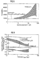
Figur 5- zeigt im Vergleich die Abhängigkeit der Permeabilitäten des erfindungsgemäßen Magnetkerns und der von Permalloy-Kernen von einer Induktionsamplitude, die durch ein erregendes Magnetfeld erzeugt wird.
Figur 6- zeigt die Abhängigkeit des Amplitudenfehlers und des Phasenfehlers vom zu messenden Strom.
Figur 7- zeigt schematisch den Magnetkern, der aus einem Band mit einer isolierenden Schicht besteht, und seine Anisotropieachse.
Figur 8- zeigt die Temperaturabhängigkeit der Permeabilität des Magnetkerns bei einem Permeabilitätsniveau von ca. 80000 im Vergleich mit der einiger typischer Ferrite.
Figur 7- ist nicht maßstabsgetreu.
- FIG. 5
- shows in comparison the dependence of the permeabilities of the magnetic core according to the invention and of Permalloy cores of an induction amplitude, which is generated by an exciting magnetic field.
- FIG. 6
- shows the dependence of the amplitude error and the phase error on the current to be measured.
- FIG. 7
- schematically shows the magnetic core, which consists of a band with an insulating layer, and its anisotropy axis.
- FIG. 8
- shows the temperature dependence of the permeability of the magnetic core at a permeability level of about 80,000 compared to that of some typical ferrites.
- FIG. 7
- is not to scale.
In einem Ausführungsbeipiel wurde ein 3 g schwerer ringförmiger Magnetkern M, der aus einem mit einer ca. 300 nm dicken isolierenden Schicht S aus Magnesiumoxid beschichtenem Band B aus einer wärmebehandelten nanokristallinen Legierung mit der Zusammensetzung Fe73,42 Cu1,04Nb2,96Si15,68B6,95 besteht, mit den Abmessungen 19 x 15 x 5,2 mm und mit einem Eisenquerschnitt von Afe = 0,077 cm2 erzeugt.In one embodiment, a 3 g ring-shaped magnetic core M consisting of a band B made of a heat-treated nanocrystalline alloy having a composition of Fe 73.42 Cu 1.04 Nb 2.96 coated with a magnesium oxide insulating layer S coated approximately 300 nm thick Si 15.68 B 6.95 , produced with the dimensions 19 x 15 x 5.2 mm and with an iron cross-section of A fe = 0.077 cm 2 .
Zur Vermeidung von Wickelspannungen wurde beim Wickeln des Bandes B zum Magnetkern M darauf geachtet, daß die Zugkraft des Bandes B mit zunehmender Bandlagenzahl kontinuierlich zurückgeht. Damit wird erreicht, daß das tangential am Magnetkern M angreifende Drehmoment über den gesamten Radius des Magnetkerns M konstant bleibt und nicht mit wachsendem Radius größer wird.To avoid winding stresses, it has been ensured during winding of the band B to the magnetic core M that the tensile force of the band B decreases continuously with increasing number of band layers. This ensures that the torque acting tangentially on the magnetic core M remains constant over the entire radius of the magnetic core M and does not increase with increasing radius.
Zur Erzielung der geforderten Magneteigenschaften wurde der Magnetkern M bei 572°C vorbehandelt, wodurch sich infolge der Ausbildung der nanokristallinen Zweiphasenstruktur der Betrag der Sättigungsmagnetostriktion von λs ≈ 24 ppm auf 0,16 ppm reduzierte. Die Aufheizrate wurde zwischen 450 °C und 520 °C von z.B. 10 K/min auf 1 K/min reduziert. Nachdem der Kern z.B. für 1 Stunde auf 572°C gehalten wurde, wurde er wieder abgekühlt.To achieve the required magnetic properties of the magnetic core M was pretreated at 572 ° C, which reduced due to the formation of the nanocrystalline two-phase structure, the amount of saturation magnetostriction of λ s ≈ 24 ppm to 0.16 ppm. The heating rate was reduced between 450 ° C and 520 ° C, for example from 10 K / min to 1 K / min. After the core was kept at 572 ° C for 1 hour, for example, it was cooled again.
Zur Einstellung der für flache lineare Hystereseschleifen (F-Schleifen) notwendigen uniaxialen Queranisotropie Ku wurde der Magnetkern M in einer weiteren Wärmebehandlung für 3,5 Stunden bei einer Temperatur von 382 °C getempert. Zur Ausrichtung der magnetischen Vorzugsrichtung, d.h. zur Erzeugung einer Anisotropieachse A wurde quer zur späteren Magnetisierungsrichtung ein äußeres Magnetfeld (H > 1000 A/cm) angelegt, das transversal zur Richtung des gewickelten Bandes B steht (siehe Figur 7). Das Magnetfeld war also parallel zur Anisotropieachse A.To set the uniaxial transverse anisotropy K u necessary for flat linear hysteresis loops (F loops), the magnetic core M was tempered in a further heat treatment for 3.5 hours at a temperature of 382 ° C. For orientation of the preferred magnetic direction, ie for generating an anisotropy axis A, an external magnetic field (H> 1000 A / cm) was applied transversely to the later magnetization direction, which is transverse to the direction of the wound strip B (see FIG. 7). The magnetic field was thus parallel to the anisotropy axis A.
Die magnetischen Eigenschaften des zweiteilig wärmebehandelten Magnetkerns M geht aus Fig. 5 hervor, wobei die Permeabilität im Gegensatz zu konventionellen kristallinen Permalloy-Kernen über einen weiten Aussteuerungsbereich hinweg nahezu konstant auf dem hohen Wert µ ≈ 82.000 lag. Dies wurde möglich, da einerseits die eingesetzte Legierung eine hohe Sättigungsinduktion von ca. 1,2 Tesla besitzt und andererseits das statische Verhältnis Remanenz- zu Sättigungsinduktion infolge der durch die Vorbehandlung hinreichend stark reduzierten Sättigungsmagnetostriktion sowie einer geringen effektiven Rauhtiefe (Ra(eff) ≈ 2,9 %) mit Br/Bm = 2,6 % ausreichend klein war.The magnetic properties of the two-part heat-treated magnetic core M are shown in FIG. 5, wherein the permeability, in contrast to conventional Permalloy crystalline cores, was almost constant at a high value μ≈82,000 over a wide control range. This was possible because on the one hand the alloy used has a high saturation induction of about 1.2 Tesla and on the other hand the static ratio remanence to saturation induction due to the saturation magnetostriction sufficiently reduced by the pretreatment and a low effective surface roughness (R a (eff) ≈ 2.9%) with B r / B m = 2.6% was sufficiently small.
Der Magnetkern M wurde zu einem Stromwandler weiterverarbeitet. Der Stromwandler wies eine Primärwindungszahl N1 von 3 und eine Sekundärwindungszahl N2 von 2000 auf und war über einen Bürdenwiderstand von 100 Ohm niederohmig im Sekundärstromkreis abgeschlossen. Die anwendungsrelevanten Größen Amplitudenfehler F und Phasenfehler ϕ gehen aus Fig. 6 hervor. Bedingt durch die ausgeprägte Linearität und hohe Permeabilität der Hystereseschleife sind beide Größen betragsmäßig klein und ihre Aussteuerungsabhängigkeit vergleichsweise gering ist. Der mittlere Phasenwinkel ϕ beträgt 0,40°. Eine Linearität des Phasenwinkels Δϕ über einen Strombereich von 0,1 bis 2 A beträgt weniger als 0,04°.The magnetic core M was further processed into a current transformer. The current transformer had a primary turn number N 1 of 3 and a secondary turn number N 2 of 2000 and was terminated by a load resistance of 100 ohm low impedance in the secondary circuit. The application-relevant magnitudes amplitude error F and phase error φ are shown in FIG. 6. Due to the pronounced linearity and high permeability of the hysteresis loop both quantities are small in size and their modulation dependence is comparatively low. The mean phase angle φ is 0.40 °. A linearity of the phase angle Δφ over a current range of 0.1 to 2 A is less than 0.04 °.
Der Magnetkern M wies eine hervorragende Alterungsbeständigkeit bis zu 150°C auf. Darüber hinaus zeigt Fig. 8 die hervorragend kleine Temperaturabhängigkeit des aus besagter nanokristalliner Legierung hergestellten Magnetkerns M, wobei sich gerade das eingestellte Permeabilitätsniveau um 80000 besonders auszeichnet.The magnetic core M had excellent aging resistance up to 150 ° C. In addition, FIG. 8 shows the outstandingly small temperature dependence of the magnetic core M produced from said nanocrystalline alloy, with the set permeability level of around 80000 being particularly pronounced.
Insgesamt war dieses Glühergebnis praktisch unabhängig davon, ob die beschriebene Wärmebehandlung als zwei unabhängige Teilschritte oder in einem einzigen Ablauf durchgeführt wurde.Overall, this glowing result was practically independent of whether the described heat treatment was performed as two independent substeps or in a single run.
Zur noch vollständigeren Reduzierung der Magnetostriktion wurde die thermische Vorbehandlung versuchsweise bei Tx= 600 °C durchgeführt. Das Glühergebnis war allerdings deutlich schlechter, denn im Gegensatz zu den oben beschriebenen hervorragenden Linearitätseigenschafen besaß die Schleife jetzt plötzlich ein hohes Remanenzverhältnis von Br/Bm = 23,5 %, wobei die Anfangspermeabilität nur noch bei µ4 ≈ 48.000 lag.For even more complete reduction of the magnetostriction, the thermal pretreatment was carried out experimentally at T x = 600 ° C. However, the glowing result was significantly worse, because in contrast to the outstanding linearity properties described above, the loop now suddenly had a high remanence ratio of B r / B m = 23.5%, the initial permeability was only at μ 4 ≈ 48,000.
Nach einer Vorbehandlung bei Tx = 520 °C reagierten die Magneteigenschaften des Magnetkerns infolge zu hoher Sättigungsmagnetostriktion sehr empfindlich auf mechanisch verspannende Einflüsse jeglicher Art. Dabei wuchs das Remanenzverhältnis bereits bei schwachen mechanischen Manipulationen von 6 % auf 20 % oder mehr an. Demzufolge war eine Verkapselung oder Kunststoffbeschichtung und damit die technologische Weiterverarbeitung des Magnetkerns zum Stromwandlerbauelement nicht mehr möglich.After a pretreatment at T x = 520 ° C, the magnetic properties of the magnetic core due to high saturation magnetostriction very sensitive to mechanical stress influences of any kind. The remanence ratio increased even with weak mechanical manipulation of 6% to 20% or more. Consequently, an encapsulation or plastic coating and thus the technological further processing of the magnetic core to the current transformer component was no longer possible.
Wurde dagegen die Vorbehandlungstemperaur von Tx = 572 °C beibehalten, aber die Temperatur der Feldwärmebehandlung auf 440 °C erhöht, behielt die Hystereseschleife zwar ihre hervorragende Linearität mit einem Remanenzverhältnis von jetzt Br/Bm = 2,4 %, aber ihre Anfangspermeabilität lag aufgrund einer zu hohen uniaxialen Anisotropieenergie Ku nur noch bei µ4 ≈ 56.000.On the contrary, when the pretreatment temperature of T x = 572 ° C was maintained but the temperature of the field heat treatment increased to 440 ° C, the hysteresis loop retained its excellent linearity with a remanence ratio of now B r / B m = 2.4%, but its initial permeability due to an excessive uniaxial anisotropy energy K u, it was only μ 4 ≈ 56,000.
Claims (17)
- Magnetic core for a current transformer- which consists of a wound strip (B) made of a ferromagnetic alloy, in which at least 50 % of the volume of the alloy is taken up by fine crystalline particles with an average particle size of 100 nm or less (nanocrystalline alloy),- which displays permeability higher than 12000 and lower than 300000,- which displays saturation magnetostriction the magnitude of which is less than 1 ppm,- which is essentially free of mechanical stress,- which has an anisotropy axis (A) along which the magnetisation of the magnetic core (M) is aligned in a particularly simple manner and which is perpendicular to a plane in which a centre line of the strip (B) extends, the alloy having a composition consisting essentially of the formulawhere M is at least one of the elements V, Nb, Ta, Ti, Mo, W, Zr and Hf, a, b, c, d, e and f are specified in atomic % and a, b, c, d, e and f satisfy the following conditions:
FeaCobCucSidBeMf,
0.5 ≤ c ≤ 2; 6.5 ≤ d ≤ 18; 5 ≤ e ≤ 14; 1 ≤ f ≤ 6, with d + e > 18 and 0 ≤ b ≤ 15, where a + b + c + d + e + f = 100,
characterised in that the strip (B) has a roughness depth Ra(eff) of less than 7 %. - Magnetic core according to claim 1, characterised in that a, b, c, d, e and f satisfy the following conditions:
c = 1; 14 ≤ d ≤ 17; 5 ≤ e ≤ 14; 2 ≤ f ≤ 4; 0 ≤ b ≤ 0.5, with 22 < d + e ≤ 24. - Magnetic core according to claim 2, characterised in that the magnitude of the saturation magnetostriction is less than 0.2 ppm.
- Magnetic core according to one of claims 1 to 3, characterised in that the magnetic core (M) displays saturation magnetisation Bs of 1.1 to 1.4 T.
- Magnetic core according to one of claims 1 to 4, characterised in that the strip (B) is provided at least on one surface with an electrically insulating layer (S).
- Magnetic core according to claim 5, characterised in that a layer of magnesium oxide is provided as the electrically insulating layer (S).
- Magnetic core according to claim 6, characterised in that the electrically insulating layer (S) has a thickness (D) of 25 nm ≤ D ≤ 3 µm.
- Magnetic core according to one of claims 1 to 7, characterised in that it is designed as a closed toroidal core, oval core or rectangular core without an air gap.
- Magnetic core according to one of claims 1 to 8, characterised in that the ratio of its mechanical elastic stress tensor multiplied by the saturation magnetostriction to its uniaxial anisotropy is less than 0.5.
- Current transformer for alternating current comprising a magnetic core according to one of claims 1 to 9, in which, in addition to the magnetic core (M) serving as a transformer core, the current transformer consists of at least one primary winding and at least one secondary winding to which a brush resistor is connected in parallel and closes the secondary circuit with low resistance.
- Current transformer according to claim 10, characterised in that the secondary winding has Nsec ≤ 2200 turns, the primary winding having Nprim = 3 turns and the current transformer being designed for a primary current Iprim ≤ 20 A.
- Process for the production of a magnetic core according to one of claims 1 to 11,- in which, after the production and winding of the strip (B) into the magnetic core (M), the magnetic core (M) is heated to a target temperature of between 450°C and 600°C and- in which the magnetic core (M) is subjected to a magnetic field of more than 100 A/cm parallel to the anisotropy axis (A) of the magnetic core (M) to be formed at a temperature below the Curie temperature of the alloy for 0.1 to 8 hours at temperatures of between 260°C and 590°C.
- Process according to claim 12,- in which the heating to the target temperature is effected at a rate of between 0.5 and 15 K/min and- in which the magnetic core (M) is kept at the target temperature for between 4 minutes and 8 hours.
- Process according to one of claims 12 to 13,- in which, before it is wound, the strip (B) is provided on at least one of its two surfaces with an electrically insulating layer (S).
- Process according to one of claims 12 to 14,- in which the magnetic core (M) is subjected to dip encapsulation before it is heated to the target temperature so that the strip (B) is provided with an electrically insulating layer (S).
- Process according to one of claims 12 to 15,- in which, at least during the treatment in the magnetic field, a plurality of identical magnetic cores (M) are stacked one on top of the other via their end faces in such a manner that the height of a stack is a multiple of the external diameter of the magnetic core (M).
- Process according to one of claims 12 to 16,- in which the magnetic core (M) is cooled to room temperature at rates of 0.1 to 5 K/min.
Applications Claiming Priority (3)
| Application Number | Priority Date | Filing Date | Title |
|---|---|---|---|
| DE19852424 | 1998-11-13 | ||
| DE19852424 | 1998-11-13 | ||
| PCT/DE1999/003631 WO2000030132A1 (en) | 1998-11-13 | 1999-11-15 | Magnetic core that is suitable for use in a current transformer, method for the production of a magnetic core and current transformer with a magnetic core |
Publications (2)
| Publication Number | Publication Date |
|---|---|
| EP1131830A1 EP1131830A1 (en) | 2001-09-12 |
| EP1131830B1 true EP1131830B1 (en) | 2006-05-10 |
Family
ID=7887721
Family Applications (1)
| Application Number | Title | Priority Date | Filing Date |
|---|---|---|---|
| EP99963241A Expired - Lifetime EP1131830B1 (en) | 1998-11-13 | 1999-11-15 | Magnetic core that is suitable for use in a current transformer, method for the production of a magnetic core and current transformer with a magnetic core |
Country Status (8)
| Country | Link |
|---|---|
| US (1) | US6507262B1 (en) |
| EP (1) | EP1131830B1 (en) |
| JP (1) | JP2002530854A (en) |
| KR (1) | KR100606515B1 (en) |
| AT (1) | ATE326056T1 (en) |
| DE (1) | DE59913420D1 (en) |
| ES (1) | ES2264277T3 (en) |
| WO (1) | WO2000030132A1 (en) |
Cited By (1)
| Publication number | Priority date | Publication date | Assignee | Title |
|---|---|---|---|---|
| DE102008051561B4 (en) * | 2008-10-14 | 2013-06-20 | Vacuumschmelze Gmbh & Co. Kg | Method for producing a current detection device |
Families Citing this family (31)
| Publication number | Priority date | Publication date | Assignee | Title |
|---|---|---|---|---|
| ES2178888T3 (en) * | 1998-03-03 | 2003-01-01 | Vacuumschmelze Gmbh | LOW FREQUENCY FILTER FOR A DIPLEXOR. |
| WO2002003082A1 (en) * | 2000-07-06 | 2002-01-10 | Infineon Technologies Ag | Current sensor and use thereof |
| DE10045705A1 (en) * | 2000-09-15 | 2002-04-04 | Vacuumschmelze Gmbh & Co Kg | Magnetic core for a transducer regulator and use of transducer regulators as well as method for producing magnetic cores for transducer regulators |
| DE10134056B8 (en) * | 2001-07-13 | 2014-05-28 | Vacuumschmelze Gmbh & Co. Kg | Process for the production of nanocrystalline magnetic cores and apparatus for carrying out the process |
| US6930581B2 (en) | 2002-02-08 | 2005-08-16 | Metglas, Inc. | Current transformer having an amorphous fe-based core |
| US7048809B2 (en) * | 2003-01-21 | 2006-05-23 | Metglas, Inc. | Magnetic implement having a linear BH loop |
| CN100378875C (en) | 2003-04-02 | 2008-04-02 | 真空融化两合公司 | Magnet core, method for the production of such a magnet core, uses of such a magnet core especially in current transformers and current-compensated inductors, and alloys and bands used for producing s |
| GB2407214A (en) * | 2003-10-14 | 2005-04-20 | Magtech A S | Variable inductor |
| DE102004024337A1 (en) * | 2004-05-17 | 2005-12-22 | Vacuumschmelze Gmbh & Co. Kg | Process for producing nanocrystalline current transformer cores, magnetic cores produced by this process, and current transformers with same |
| KR100621433B1 (en) * | 2004-07-09 | 2006-09-19 | (주) 아모센스 | Watt-hour meter including magnetic core |
| FR2877486B1 (en) | 2004-10-29 | 2007-03-30 | Imphy Alloys Sa | NANOCRYSTALLINE TORE FOR CURRENT SENSOR, SINGLE AND DOUBLE FLOOR ENERGY METERS AND CURRENT PROBES INCORPORATING SAME |
| US7473325B2 (en) | 2004-12-17 | 2009-01-06 | Hitachi Metals, Ltd. | Current transformer core, current transformer and power meter |
| CN1316521C (en) * | 2005-06-23 | 2007-05-16 | 安泰科技股份有限公司 | Anti-DC component current transformer core and mfg. method and use thereof |
| DE102005034486A1 (en) | 2005-07-20 | 2007-02-01 | Vacuumschmelze Gmbh & Co. Kg | Process for the production of a soft magnetic core for generators and generator with such a core |
| JP2007299838A (en) | 2006-04-28 | 2007-11-15 | Hitachi Metals Ltd | Magnetic core for current transformer, current transformer using same, and electric power meter |
| US20070273467A1 (en) * | 2006-05-23 | 2007-11-29 | Jorg Petzold | Magnet Core, Methods For Its Production And Residual Current Device |
| US7909945B2 (en) * | 2006-10-30 | 2011-03-22 | Vacuumschmelze Gmbh & Co. Kg | Soft magnetic iron-cobalt-based alloy and method for its production |
| DE102007017338A1 (en) * | 2007-02-13 | 2008-08-14 | Patent-Treuhand-Gesellschaft für elektrische Glühlampen mbH | Ignition transformer for a discharge lamp |
| US8012270B2 (en) | 2007-07-27 | 2011-09-06 | Vacuumschmelze Gmbh & Co. Kg | Soft magnetic iron/cobalt/chromium-based alloy and process for manufacturing it |
| US9057115B2 (en) * | 2007-07-27 | 2015-06-16 | Vacuumschmelze Gmbh & Co. Kg | Soft magnetic iron-cobalt-based alloy and process for manufacturing it |
| CN101685705B (en) * | 2008-09-24 | 2013-11-13 | 零八一电子集团四川力源电子有限公司 | Double-protection-box oppositely-clamping iron-based amorphous alloy band magnet core |
| DE102010004223B4 (en) | 2010-01-08 | 2013-12-05 | Vacuumschmelze Gmbh & Co. Kg | Method for producing a current detection device |
| WO2012064871A2 (en) * | 2010-11-09 | 2012-05-18 | California Institute Of Technology | Ferromagnetic cores of amorphouse ferromagnetic metal alloys and electonic devices having the same |
| DE102010060740A1 (en) * | 2010-11-23 | 2012-05-24 | Vacuumschmelze Gmbh & Co. Kg | Soft magnetic metal strip for electromechanical components |
| JP5886024B2 (en) * | 2011-12-19 | 2016-03-16 | 株式会社東芝 | Magnetic resonance imaging system |
| WO2015080693A1 (en) | 2013-11-26 | 2015-06-04 | Schneider Electric USA, Inc. | Wireless batteryless data processing unit |
| US20170092412A1 (en) * | 2015-09-26 | 2017-03-30 | Mathew J. Manusharow | Package integrated power inductors using lithographically defined vias |
| US10163557B2 (en) | 2015-12-17 | 2018-12-25 | Intel Corporation | Helical plated through-hole package inductor |
| ES2581127B2 (en) * | 2016-04-13 | 2017-05-04 | Universidad Complutense De Madrid | Label, system and method for long-distance object detection |
| RU2716282C1 (en) * | 2018-12-29 | 2020-03-11 | Общество С Ограниченной Ответственностью "Крокус Наноэлектроника" (Ооо "Крокус Наноэлектроника") | Thin-film toroidal core with shape anisotropy, inductance coil and transformer, containing thereof |
| DE102019105215A1 (en) * | 2019-03-01 | 2020-09-03 | Vacuumschmelze Gmbh & Co. Kg | Alloy and method of making a magnetic core |
Family Cites Families (12)
| Publication number | Priority date | Publication date | Assignee | Title |
|---|---|---|---|---|
| US4451876A (en) * | 1981-06-19 | 1984-05-29 | Hitachi Metals, Ltd. | Switching regulator |
| JPS6039160B2 (en) * | 1982-07-22 | 1985-09-04 | 新日本製鐵株式会社 | Magnetic amorphous alloy material with excellent insulation and corrosion resistance |
| JPH0610105A (en) * | 1986-12-15 | 1994-01-18 | Hitachi Metals Ltd | Fe base soft magnetic alloy |
| JPH0610104A (en) * | 1986-12-15 | 1994-01-18 | Hitachi Metals Ltd | Fe base soft magnetic alloy |
| US4881989A (en) | 1986-12-15 | 1989-11-21 | Hitachi Metals, Ltd. | Fe-base soft magnetic alloy and method of producing same |
| JPH0711396A (en) * | 1986-12-15 | 1995-01-13 | Hitachi Metals Ltd | Fe base soft magnetic alloy |
| JPS6479342A (en) * | 1986-12-15 | 1989-03-24 | Hitachi Metals Ltd | Fe-base soft magnetic alloy and its production |
| JPH05222493A (en) * | 1992-02-13 | 1993-08-31 | Nippon Steel Corp | Ferrous high permeability amorphous alloy |
| DE4210748C1 (en) | 1992-04-01 | 1993-12-16 | Vacuumschmelze Gmbh | Current transformers for pulse current sensitive residual current circuit breakers, residual current circuit breakers with such a current transformer, and method for heat treatment of the iron alloy strip for its magnetic core |
| EP0637038B1 (en) * | 1993-07-30 | 1998-03-11 | Hitachi Metals, Ltd. | Magnetic core for pulse transformer and pulse transformer made thereof |
| JPH09143640A (en) * | 1995-11-21 | 1997-06-03 | Kawasaki Steel Corp | Wide amorphous alloy foil for power transformer iron core |
| FR2755292B1 (en) * | 1996-10-25 | 1998-11-20 | Mecagis | PROCESS FOR MANUFACTURING A MAGNETIC CORE IN NANOCRYSTALLINE SOFT MAGNETIC MATERIAL |
-
1999
- 1999-11-15 US US09/831,800 patent/US6507262B1/en not_active Expired - Lifetime
- 1999-11-15 AT AT99963241T patent/ATE326056T1/en not_active IP Right Cessation
- 1999-11-15 ES ES99963241T patent/ES2264277T3/en not_active Expired - Lifetime
- 1999-11-15 DE DE59913420T patent/DE59913420D1/en not_active Expired - Lifetime
- 1999-11-15 KR KR1020017006033A patent/KR100606515B1/en active IP Right Grant
- 1999-11-15 WO PCT/DE1999/003631 patent/WO2000030132A1/en active IP Right Grant
- 1999-11-15 EP EP99963241A patent/EP1131830B1/en not_active Expired - Lifetime
- 1999-11-15 JP JP2000583053A patent/JP2002530854A/en active Pending
Cited By (1)
| Publication number | Priority date | Publication date | Assignee | Title |
|---|---|---|---|---|
| DE102008051561B4 (en) * | 2008-10-14 | 2013-06-20 | Vacuumschmelze Gmbh & Co. Kg | Method for producing a current detection device |
Also Published As
| Publication number | Publication date |
|---|---|
| ES2264277T3 (en) | 2006-12-16 |
| ATE326056T1 (en) | 2006-06-15 |
| WO2000030132A1 (en) | 2000-05-25 |
| DE59913420D1 (en) | 2006-06-14 |
| EP1131830A1 (en) | 2001-09-12 |
| US6507262B1 (en) | 2003-01-14 |
| KR20010080443A (en) | 2001-08-22 |
| JP2002530854A (en) | 2002-09-17 |
| KR100606515B1 (en) | 2006-07-31 |
Similar Documents
| Publication | Publication Date | Title |
|---|---|---|
| EP1131830B1 (en) | Magnetic core that is suitable for use in a current transformer, method for the production of a magnetic core and current transformer with a magnetic core | |
| EP1114429B1 (en) | Current transformer with a direct current tolerance | |
| DE3001889C2 (en) | Process for the production of a magnetic glassy alloy foil | |
| DE2708151C2 (en) | Use of glassy alloys for power transformers or signal converters | |
| EP1609159B1 (en) | Magnet core, method for the production of such a magnet core, uses of such a magnet core especially in current transformers and current-compensated inductors, and alloys and bands used for producing such a magnet core | |
| EP1747566B1 (en) | Current transformer core and method for producing a current transformer core | |
| EP1317758B1 (en) | Half-cycle transductor with a magnetic core, use of half-cycle transductors and method for producing magnetic cores for half-cycle transductors | |
| DE2835389A1 (en) | MAGNETIC ALLOY | |
| DE202005022087U1 (en) | Nanocrystalline core for current sensors, one- and two-stage energy meters and these integrating current probes | |
| DE3737266C2 (en) | Soft magnetic thin film | |
| EP1129459B1 (en) | Use of a magnetic core for a current transformer, method for the production of a magnetic core and current transformer with a magnetic core | |
| US6432226B2 (en) | Magnetic glassy alloys for high frequency applications | |
| US5192375A (en) | Fe-based soft magnetic alloy | |
| DE19739959C2 (en) | Hard magnetic material | |
| EP0084138B1 (en) | Near-zero magnetostrictive glassy metal alloys with high magnetic and thermal stability | |
| DE3619659A1 (en) | Fe-based amorphous alloy | |
| JP2919886B2 (en) | Fe-based soft magnetic alloy | |
| EP0329704B1 (en) | Near-zero magnetostrictive glassy metal alloys for high frequency applications | |
| DE102018131481A1 (en) | MASSIVE AMORPHY ALLOY AND METHOD FOR PRODUCING SUCH ALLOY |
Legal Events
| Date | Code | Title | Description |
|---|---|---|---|
| PUAI | Public reference made under article 153(3) epc to a published international application that has entered the european phase |
Free format text: ORIGINAL CODE: 0009012 |
|
| 17P | Request for examination filed |
Effective date: 20010405 |
|
| AK | Designated contracting states |
Kind code of ref document: A1 Designated state(s): AT BE CH CY DE DK ES FI FR GB GR IE IT LI LU MC NL PT SE |
|
| 17Q | First examination report despatched |
Effective date: 20030903 |
|
| GRAP | Despatch of communication of intention to grant a patent |
Free format text: ORIGINAL CODE: EPIDOSNIGR1 |
|
| GRAS | Grant fee paid |
Free format text: ORIGINAL CODE: EPIDOSNIGR3 |
|
| GRAA | (expected) grant |
Free format text: ORIGINAL CODE: 0009210 |
|
| AK | Designated contracting states |
Kind code of ref document: B1 Designated state(s): AT BE CH CY DE DK ES FI FR GB GR IE IT LI LU MC NL PT SE |
|
| PG25 | Lapsed in a contracting state [announced via postgrant information from national office to epo] |
Ref country code: NL Free format text: LAPSE BECAUSE OF FAILURE TO SUBMIT A TRANSLATION OF THE DESCRIPTION OR TO PAY THE FEE WITHIN THE PRESCRIBED TIME-LIMIT Effective date: 20060510 Ref country code: IT Free format text: LAPSE BECAUSE OF FAILURE TO SUBMIT A TRANSLATION OF THE DESCRIPTION OR TO PAY THE FEE WITHIN THE PRESCRIBED TIME-LIMIT;WARNING: LAPSES OF ITALIAN PATENTS WITH EFFECTIVE DATE BEFORE 2007 MAY HAVE OCCURRED AT ANY TIME BEFORE 2007. THE CORRECT EFFECTIVE DATE MAY BE DIFFERENT FROM THE ONE RECORDED. Effective date: 20060510 Ref country code: IE Free format text: LAPSE BECAUSE OF FAILURE TO SUBMIT A TRANSLATION OF THE DESCRIPTION OR TO PAY THE FEE WITHIN THE PRESCRIBED TIME-LIMIT Effective date: 20060510 Ref country code: GB Free format text: LAPSE BECAUSE OF FAILURE TO SUBMIT A TRANSLATION OF THE DESCRIPTION OR TO PAY THE FEE WITHIN THE PRESCRIBED TIME-LIMIT Effective date: 20060510 |
|
| REG | Reference to a national code |
Ref country code: GB Ref legal event code: FG4D Free format text: NOT ENGLISH |
|
| REG | Reference to a national code |
Ref country code: CH Ref legal event code: EP |
|
| REF | Corresponds to: |
Ref document number: 59913420 Country of ref document: DE Date of ref document: 20060614 Kind code of ref document: P |
|
| REG | Reference to a national code |
Ref country code: IE Ref legal event code: FG4D Free format text: LANGUAGE OF EP DOCUMENT: GERMAN |
|
| REG | Reference to a national code |
Ref country code: CH Ref legal event code: NV Representative=s name: R. A. EGLI & CO. PATENTANWAELTE |
|
| PG25 | Lapsed in a contracting state [announced via postgrant information from national office to epo] |
Ref country code: DK Free format text: LAPSE BECAUSE OF FAILURE TO SUBMIT A TRANSLATION OF THE DESCRIPTION OR TO PAY THE FEE WITHIN THE PRESCRIBED TIME-LIMIT Effective date: 20060810 |
|
| REG | Reference to a national code |
Ref country code: SE Ref legal event code: TRGR |
|
| PG25 | Lapsed in a contracting state [announced via postgrant information from national office to epo] |
Ref country code: PT Free format text: LAPSE BECAUSE OF FAILURE TO SUBMIT A TRANSLATION OF THE DESCRIPTION OR TO PAY THE FEE WITHIN THE PRESCRIBED TIME-LIMIT Effective date: 20061010 |
|
| NLV1 | Nl: lapsed or annulled due to failure to fulfill the requirements of art. 29p and 29m of the patents act | ||
| PG25 | Lapsed in a contracting state [announced via postgrant information from national office to epo] |
Ref country code: MC Free format text: LAPSE BECAUSE OF NON-PAYMENT OF DUE FEES Effective date: 20061130 Ref country code: BE Free format text: LAPSE BECAUSE OF NON-PAYMENT OF DUE FEES Effective date: 20061130 |
|
| ET | Fr: translation filed | ||
| GBV | Gb: ep patent (uk) treated as always having been void in accordance with gb section 77(7)/1977 [no translation filed] |
Effective date: 20060510 |
|
| REG | Reference to a national code |
Ref country code: ES Ref legal event code: FG2A Ref document number: 2264277 Country of ref document: ES Kind code of ref document: T3 |
|
| REG | Reference to a national code |
Ref country code: IE Ref legal event code: FD4D |
|
| PLBE | No opposition filed within time limit |
Free format text: ORIGINAL CODE: 0009261 |
|
| STAA | Information on the status of an ep patent application or granted ep patent |
Free format text: STATUS: NO OPPOSITION FILED WITHIN TIME LIMIT |
|
| 26N | No opposition filed |
Effective date: 20070213 |
|
| BERE | Be: lapsed |
Owner name: VACUUMSCHMELZE G.M.B.H. Effective date: 20061130 |
|
| PG25 | Lapsed in a contracting state [announced via postgrant information from national office to epo] |
Ref country code: AT Free format text: LAPSE BECAUSE OF NON-PAYMENT OF DUE FEES Effective date: 20061115 |
|
| PG25 | Lapsed in a contracting state [announced via postgrant information from national office to epo] |
Ref country code: GR Free format text: LAPSE BECAUSE OF FAILURE TO SUBMIT A TRANSLATION OF THE DESCRIPTION OR TO PAY THE FEE WITHIN THE PRESCRIBED TIME-LIMIT Effective date: 20060811 |
|
| PG25 | Lapsed in a contracting state [announced via postgrant information from national office to epo] |
Ref country code: LU Free format text: LAPSE BECAUSE OF NON-PAYMENT OF DUE FEES Effective date: 20061115 |
|
| PG25 | Lapsed in a contracting state [announced via postgrant information from national office to epo] |
Ref country code: CY Free format text: LAPSE BECAUSE OF FAILURE TO SUBMIT A TRANSLATION OF THE DESCRIPTION OR TO PAY THE FEE WITHIN THE PRESCRIBED TIME-LIMIT Effective date: 20060510 |
|
| PGFP | Annual fee paid to national office [announced via postgrant information from national office to epo] |
Ref country code: CH Payment date: 20141120 Year of fee payment: 16 Ref country code: FI Payment date: 20141119 Year of fee payment: 16 Ref country code: SE Payment date: 20141120 Year of fee payment: 16 |
|
| REG | Reference to a national code |
Ref country code: FR Ref legal event code: PLFP Year of fee payment: 17 |
|
| REG | Reference to a national code |
Ref country code: CH Ref legal event code: PL |
|
| PG25 | Lapsed in a contracting state [announced via postgrant information from national office to epo] |
Ref country code: LI Free format text: LAPSE BECAUSE OF NON-PAYMENT OF DUE FEES Effective date: 20151130 Ref country code: CH Free format text: LAPSE BECAUSE OF NON-PAYMENT OF DUE FEES Effective date: 20151130 |
|
| PG25 | Lapsed in a contracting state [announced via postgrant information from national office to epo] |
Ref country code: SE Free format text: LAPSE BECAUSE OF NON-PAYMENT OF DUE FEES Effective date: 20151116 |
|
| REG | Reference to a national code |
Ref country code: FR Ref legal event code: PLFP Year of fee payment: 18 |
|
| PG25 | Lapsed in a contracting state [announced via postgrant information from national office to epo] |
Ref country code: FI Free format text: LAPSE BECAUSE OF NON-PAYMENT OF DUE FEES Effective date: 20151115 |
|
| REG | Reference to a national code |
Ref country code: FR Ref legal event code: PLFP Year of fee payment: 19 |
|
| PGFP | Annual fee paid to national office [announced via postgrant information from national office to epo] |
Ref country code: FR Payment date: 20171129 Year of fee payment: 19 |
|
| PGFP | Annual fee paid to national office [announced via postgrant information from national office to epo] |
Ref country code: ES Payment date: 20171222 Year of fee payment: 19 Ref country code: IT Payment date: 20171122 Year of fee payment: 19 |
|
| PGFP | Annual fee paid to national office [announced via postgrant information from national office to epo] |
Ref country code: DE Payment date: 20190131 Year of fee payment: 20 |
|
| PG25 | Lapsed in a contracting state [announced via postgrant information from national office to epo] |
Ref country code: FR Free format text: LAPSE BECAUSE OF NON-PAYMENT OF DUE FEES Effective date: 20181130 Ref country code: IT Free format text: LAPSE BECAUSE OF NON-PAYMENT OF DUE FEES Effective date: 20181115 |
|
| REG | Reference to a national code |
Ref country code: DE Ref legal event code: R071 Ref document number: 59913420 Country of ref document: DE |
|
| REG | Reference to a national code |
Ref country code: ES Ref legal event code: FD2A Effective date: 20200103 |
|
| PG25 | Lapsed in a contracting state [announced via postgrant information from national office to epo] |
Ref country code: ES Free format text: LAPSE BECAUSE OF NON-PAYMENT OF DUE FEES Effective date: 20181116 |