EP1130143A1 - Fachbildeeinrichtung für Webmaschinen - Google Patents
Fachbildeeinrichtung für Webmaschinen Download PDFInfo
- Publication number
- EP1130143A1 EP1130143A1 EP01103847A EP01103847A EP1130143A1 EP 1130143 A1 EP1130143 A1 EP 1130143A1 EP 01103847 A EP01103847 A EP 01103847A EP 01103847 A EP01103847 A EP 01103847A EP 1130143 A1 EP1130143 A1 EP 1130143A1
- Authority
- EP
- European Patent Office
- Prior art keywords
- sleeve
- forming device
- lip seal
- strand
- shed
- Prior art date
- Legal status (The legal status is an assumption and is not a legal conclusion. Google has not performed a legal analysis and makes no representation as to the accuracy of the status listed.)
- Granted
Links
- 238000009941 weaving Methods 0.000 title claims description 6
- 239000000428 dust Substances 0.000 claims abstract description 19
- 230000015572 biosynthetic process Effects 0.000 claims description 8
- 238000001556 precipitation Methods 0.000 claims description 7
- 238000007789 sealing Methods 0.000 abstract description 2
- 241000209035 Ilex Species 0.000 description 2
- 230000007257 malfunction Effects 0.000 description 2
- 229920002635 polyurethane Polymers 0.000 description 1
- 239000004814 polyurethane Substances 0.000 description 1
- 230000002265 prevention Effects 0.000 description 1
- 230000000284 resting effect Effects 0.000 description 1
- 238000009420 retrofitting Methods 0.000 description 1
- 238000013024 troubleshooting Methods 0.000 description 1
Images
Classifications
-
- D—TEXTILES; PAPER
- D03—WEAVING
- D03C—SHEDDING MECHANISMS; PATTERN CARDS OR CHAINS; PUNCHING OF CARDS; DESIGNING PATTERNS
- D03C3/00—Jacquards
- D03C3/24—Features common to jacquards of different types
- D03C3/44—Lingoes
Definitions
- the present invention relates to a shedding device for weaving machines, whose warp threads run in strands between an upper compartment position and one Sub-compartment position can be moved back and forth, whereby for the respective provision of the strands in the sub-compartment position on each strand, in a sheathing Sleeve axially displaceable tension spring that attacks on a pull-down floor or pull-down bar of a pull-down frame is attached.
- the essential specialist training facilities are, among others, the so-called Jacqard machines, in which two blanks over a common roller train are connected at the lower end, the boards depending on the control, for example, using magnetic means, with two lifting knives constantly moving in opposite directions can be coupled, which means, for example, that attached to the roller train Strand and thus the relevant warp thread between a controlled lifting movement an upper subject position and a lower subject position is granted.
- Jacqard machines in which two blanks over a common roller train are connected at the lower end, the boards depending on the control, for example, using magnetic means, with two lifting knives constantly moving in opposite directions can be coupled, which means, for example, that attached to the roller train Strand and thus the relevant warp thread between a controlled lifting movement an upper subject position and a lower subject position is granted.
- the respective resetting of the strands in the sub-compartment position grips each strand a tension spring on a pull-down floor or on pull-down bars a pull-down frame are attached.
- the object of the present invention is therefore to create a possibility that every dust deposit and every fluff on the return springs effectively prevents downtimes due to such malfunctions omitted.
- this is initially achieved in that the axial end face a device for preventing movement relative to the strand in question of dust and lint formation on the return spring becomes.
- the device for preventing dust precipitation can preferably be used and lint formation on the retraction spring, the strand and / or hook in question or connecting means surrounding and at this (h) circumferentially hermetic tightly fitting, non-displaceable with the relevant end face of the sleeve connected lip seal.
- the lip seal can be replaced in one end Cage arranged in the sleeve or directly on the end face of the sleeve in this is used.
- the lip seal on the strand and / or on the hook or connecting means to be effective as dust and lint wipers.
- the lip seal is preferably a micro lip ring seal.
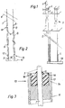
- the shedding device for weaving machines according to FIG. 1 is a so-called Open compartment jacquard machine, in which two sinkers 1 u. 2 over one common roller train 3 are connected at the lower end, the boards depending on the control, here via the magnetic means 4, with two constantly counter-rotating moving lifting knives 5 u. 6 can be coupled, whereby the attached to the roller train 3 Strand 7 and thus the relevant warp thread 8 a controlled lifting movement between an upper compartment position (left side Fig. 1) and a lower compartment position (right side) is issued.
- Tension spring 9 is surrounded by a sheathed sleeve 11 in which axially moves the relevant return spring (Fig. 2).
- the device 13 for preventing Dust and lint formation on the return spring the one in question Strand 7 or hook or connecting means surrounding and on this (m) circumferentially hermetically sealed, non-displaceable with the relevant Lip seal connected to the front of the sleeve.
- the lip seal on the wire and / or on the hook or lanyard as dust and lint wipers effective.
- the lip seal 14 is preferably interchangeable in an end face in the Sleeve 11 arranged cage 17 used.
- the cage has an end face an annular shoulder 16, which has an expansion ring-like protrusion 18 on the body of the Lips sealing behind.
- an inventive device for Prevention of dust and fluff on the return spring can also be provided simultaneously on both end faces of the sleeve in question.
- the lip seal can preferably be a micro lip ring seal be, which preferably consists of polyurethane or the like, which also without a cage can be arranged directly on the face of the sleeve.
Landscapes
- Engineering & Computer Science (AREA)
- Textile Engineering (AREA)
- Auxiliary Weaving Apparatuses, Weavers' Tools, And Shuttles (AREA)
- Looms (AREA)
- Yarns And Mechanical Finishing Of Yarns Or Ropes (AREA)
- Sealing Using Fluids, Sealing Without Contact, And Removal Of Oil (AREA)
Abstract
Description
- Fig. 1
- eine Fachbildeeinrichtung für Webmaschinen, in schematischer, teilweise schaubildartiger, ausschnittweisen Darstellung;
- Fig. 2
- in grösserem Massstab eine Litzenanordnung mit einer niederzugbodenseitigen
sowie einer kettseitigen Festverbindung zwischen
Haken resp. Litze und Hülse der Anordnung gemäss Fig. 1;
und - Fig. 3
- in grösserem Massstab im Schnitt die erfindungsgemässe Vorrichtung zur Verhinderung von Staubniederschlag und Flusenbildung an der Rückzugfeder in Form einer die betreffende Litze umgebenden und an dieser anliegenden, verschiebungsfest mit der betreffenden Stirnseite der Hülse verbundenen Lippendichtung.
Claims (6)
- Fachbildeeinrichtung für Webmaschinen, deren in Litzen geführte Kettfäden zwischen einer Oberfachstellung und einer Unterfachstellung hin- und herbewegbar sind, wobei für die jeweilige Rückstellung der Litzen in die Unterfachstellung an jeder Litze eine, in einer ummantelnden Hülse axial verschiebbare Zugfeder angreift, die an einem Niederzugboden oder Niederzugstab eines Niederzugrahmens befestigt ist,
dadurch gekennzeichnet, dass stirnseitig der axial relativ zur betreffenden Litze (7) bewegbaren Hülse (11) eine Vorrichtung (13) zur Verhinderung von Staubniederschlag und Flusenbildung an der Rückzugfeder (9) angeordnet ist. - Fachbildeeinrichtung nach Anspruch 1, dadurch gekennzeichnet, dass die Vorrichtung zur Verhinderung von Staubniederschlag und Flusenbildung an der Rückzugfeder eine die betreffende Litze (7) und/oder Haken oder Verbindungsmittel umgebende und an dieser(m) umfänglich hermetisch dichtend anliegende, verschiebungsfest mit der betreffenden Stirnseite der Hülse (11) verbundene Lippendichtung (14) ist.
- Fachbildeeinrichtung nach Anspruch 2, dadurch gekennzeichnet, dass die Lippendichtung (14) auswechselbar in einem stirnseitig in der Hülse (11) angeordneten Käfig (17) eingesetzt ist.
- Fachbildeeinrichtung nach Anspruch 2, dadurch gekennzeichnet, dass die Lippendichtung (14) stirnseitig in der Hülse (11) eingesetzt ist.
- Fachbildeeinrichtung nach Anspruch 2, dadurch gekennzeichnet, dass die Lippendichtung (14) an der Litze und/oder am Haken oder Verbindungsmittel als Staub- und Flusenabstreifer wirksam ist.
- Fachbildeeinrichtung nach Anspruch 2, dadurch gekennzeichnet, dass die Lippendichtung (14) eine Micro-Lippenring-Dichtung ist.
Applications Claiming Priority (2)
| Application Number | Priority Date | Filing Date | Title |
|---|---|---|---|
| CH00399/00A CH694020A5 (de) | 2000-03-01 | 2000-03-01 | Fachbildeeinrichtung fuer Webmaschinen. |
| CH3992000 | 2000-03-01 |
Publications (2)
| Publication Number | Publication Date |
|---|---|
| EP1130143A1 true EP1130143A1 (de) | 2001-09-05 |
| EP1130143B1 EP1130143B1 (de) | 2007-01-17 |
Family
ID=4514169
Family Applications (1)
| Application Number | Title | Priority Date | Filing Date |
|---|---|---|---|
| EP01103847A Expired - Lifetime EP1130143B1 (de) | 2000-03-01 | 2001-02-16 | Fachbildeeinrichtung für Webmaschinen |
Country Status (5)
| Country | Link |
|---|---|
| US (1) | US6367512B2 (de) |
| EP (1) | EP1130143B1 (de) |
| AT (1) | ATE351935T1 (de) |
| CH (1) | CH694020A5 (de) |
| DE (1) | DE50111879D1 (de) |
Cited By (1)
| Publication number | Priority date | Publication date | Assignee | Title |
|---|---|---|---|---|
| WO2021197279A1 (zh) * | 2020-03-30 | 2021-10-07 | 宁波帕瓦莱斯智能科技有限公司 | 光伏推杆的除砂除污装置 |
Families Citing this family (4)
| Publication number | Priority date | Publication date | Assignee | Title |
|---|---|---|---|---|
| BE1015048A4 (nl) * | 2002-07-19 | 2004-09-07 | Wiele Michel Van De Nv | Inrichting voor het bevestigen van terugtrekveren in een harnas van een jacquardweefmachine. |
| FR3043096B1 (fr) * | 2015-10-29 | 2018-05-04 | Staubli Faverges | Machine de formation de la foule |
| FR3054245B1 (fr) * | 2016-07-22 | 2018-08-31 | Staubli Faverges | Machine de formation de la foule et metier a tisser comprenant une telle machine. |
| CN106381594B (zh) * | 2016-11-29 | 2018-03-13 | 江苏悦达家纺有限公司 | 一种具有防尘的装造装置 |
Citations (4)
| Publication number | Priority date | Publication date | Assignee | Title |
|---|---|---|---|---|
| DE2651057A1 (de) * | 1976-11-09 | 1978-05-11 | Schnitzler & Vogel | Weblitze |
| EP0094270A2 (de) * | 1982-05-10 | 1983-11-16 | Jean Michel Rinet | Einheit gebildet aus einem Gegenzugorgan und einer Litze eines Fachbildungsmechanismus für einen Webstuhl |
| EP0292632A2 (de) * | 1987-05-29 | 1988-11-30 | CREAZIONI TESSILI BORSA DI CESARINO BORSA & C. S.a.s. | Elastische Spannungsvorrichtung für Jacquardmaschine |
| JPH0397935A (ja) * | 1990-04-12 | 1991-04-23 | Yagimitsuru Taoru Kk | 織機における矢金 |
Family Cites Families (2)
| Publication number | Priority date | Publication date | Assignee | Title |
|---|---|---|---|---|
| US4513789A (en) * | 1983-06-13 | 1985-04-30 | The Baxter Corporation | Jacquard harness attachment mechanism |
| EP0369939A1 (de) * | 1988-11-16 | 1990-05-23 | GebràDer Sulzer Aktiengesellschaft | Schaftträger für eine Webmaschine |
-
2000
- 2000-03-01 CH CH00399/00A patent/CH694020A5/de not_active IP Right Cessation
-
2001
- 2001-01-31 US US09/773,301 patent/US6367512B2/en not_active Expired - Fee Related
- 2001-02-16 EP EP01103847A patent/EP1130143B1/de not_active Expired - Lifetime
- 2001-02-16 AT AT01103847T patent/ATE351935T1/de not_active IP Right Cessation
- 2001-02-16 DE DE50111879T patent/DE50111879D1/de not_active Expired - Fee Related
Patent Citations (4)
| Publication number | Priority date | Publication date | Assignee | Title |
|---|---|---|---|---|
| DE2651057A1 (de) * | 1976-11-09 | 1978-05-11 | Schnitzler & Vogel | Weblitze |
| EP0094270A2 (de) * | 1982-05-10 | 1983-11-16 | Jean Michel Rinet | Einheit gebildet aus einem Gegenzugorgan und einer Litze eines Fachbildungsmechanismus für einen Webstuhl |
| EP0292632A2 (de) * | 1987-05-29 | 1988-11-30 | CREAZIONI TESSILI BORSA DI CESARINO BORSA & C. S.a.s. | Elastische Spannungsvorrichtung für Jacquardmaschine |
| JPH0397935A (ja) * | 1990-04-12 | 1991-04-23 | Yagimitsuru Taoru Kk | 織機における矢金 |
Non-Patent Citations (1)
| Title |
|---|
| PATENT ABSTRACTS OF JAPAN vol. 015, no. 282 (C - 0850) 17 July 1991 (1991-07-17) * |
Cited By (1)
| Publication number | Priority date | Publication date | Assignee | Title |
|---|---|---|---|---|
| WO2021197279A1 (zh) * | 2020-03-30 | 2021-10-07 | 宁波帕瓦莱斯智能科技有限公司 | 光伏推杆的除砂除污装置 |
Also Published As
| Publication number | Publication date |
|---|---|
| US6367512B2 (en) | 2002-04-09 |
| US20010018934A1 (en) | 2001-09-06 |
| CH694020A5 (de) | 2004-06-15 |
| DE50111879D1 (de) | 2007-03-08 |
| EP1130143B1 (de) | 2007-01-17 |
| ATE351935T1 (de) | 2007-02-15 |
Similar Documents
| Publication | Publication Date | Title |
|---|---|---|
| DE3818680C5 (de) | Vorrichtung zum Bilden einer Dreherkante | |
| EP3670721B1 (de) | Vorrichtung zum bilden einer dreherkante | |
| DE19600314C2 (de) | Relais mit zwangsgeführten Kontaktsätzen | |
| DE3447620A1 (de) | Linearer waelzlageraufbau | |
| DE60312581T2 (de) | Weblitze und Verfahren zu ihrer Herstellung, Fachbildungsvorrichtung und Webmaschine mit einer solchen Weblitze | |
| EP1130143A1 (de) | Fachbildeeinrichtung für Webmaschinen | |
| EP1428916A2 (de) | Vorrichtung zum Bilden einer Dreherkante | |
| DD240223A1 (de) | Mustersteuereinrichtung fuer textilmaschinen | |
| EP2606167A2 (de) | Webblatt und webmaschine zur webmusterbildung bei geweben mit zusatzmustereffekten | |
| DE4404451C2 (de) | Dreherleistenvorrichtung | |
| EP0371257A1 (de) | Vorrichtung zum Bilden einer Dreherkante zum Einsatz auf einer Jacquard-Maschine | |
| EP0726342B1 (de) | Greiferwebmaschine mit Führungsmitteln | |
| DD284921A5 (de) | Platinensteuerung der offenbach-jacquardmaschine einer plueschwebmaschine, insbesondere einer doppelteppich-webmaschine | |
| DE602005004958T2 (de) | Fachbildemechanismus, Dreipositions-Fachbildemechanismus und Webmaschine mit einem solchen Fachbildungsmechanismus | |
| DE2939421B1 (de) | Vorrichtung zum Heben und Senken der Kettfaeden einer Webmaschine | |
| DE1535864A1 (de) | Weblitze | |
| EP0248364B1 (de) | Vorrichtung zum Bilden einer mit einer Bindung versehenen Gewebekante | |
| DE602004001487T2 (de) | Vorrichtung zum Befestigen und Führen einer oder mehrerer Flaschenzugkordeln einer Jacquardmaschine | |
| DE707130C (de) | Webschaft | |
| AT202079B (de) | Webschaft | |
| DE630070C (de) | Dreherhalblitze | |
| AT262902B (de) | Jacquardmaschine | |
| DE19858013A1 (de) | Verbindung zwischen Schaftstab und Seitenstütze bei Webschäften | |
| EP0963469A1 (de) | Greiferwebmaschine | |
| EP0723040B1 (de) | Fachbilde-Vorrichtung und Verfahren zur Steuerung einer Jacquardmaschine mit drei definierten Fachstellungen |
Legal Events
| Date | Code | Title | Description |
|---|---|---|---|
| PUAI | Public reference made under article 153(3) epc to a published international application that has entered the european phase |
Free format text: ORIGINAL CODE: 0009012 |
|
| AK | Designated contracting states |
Kind code of ref document: A1 Designated state(s): AT BE CH CY DE DK ES FI FR GB GR IE IT LI LU MC NL PT SE TR |
|
| AX | Request for extension of the european patent |
Free format text: AL;LT;LV;MK;RO;SI |
|
| 17P | Request for examination filed |
Effective date: 20020305 |
|
| AKX | Designation fees paid |
Free format text: AT BE CH CY DE DK ES FI FR GB GR IE IT LI LU MC NL PT SE TR |
|
| GRAP | Despatch of communication of intention to grant a patent |
Free format text: ORIGINAL CODE: EPIDOSNIGR1 |
|
| GRAS | Grant fee paid |
Free format text: ORIGINAL CODE: EPIDOSNIGR3 |
|
| GRAA | (expected) grant |
Free format text: ORIGINAL CODE: 0009210 |
|
| AK | Designated contracting states |
Kind code of ref document: B1 Designated state(s): AT BE CH CY DE DK ES FI FR GB GR IE IT LI LU MC NL PT SE TR |
|
| PG25 | Lapsed in a contracting state [announced via postgrant information from national office to epo] |
Ref country code: DK Free format text: LAPSE BECAUSE OF FAILURE TO SUBMIT A TRANSLATION OF THE DESCRIPTION OR TO PAY THE FEE WITHIN THE PRESCRIBED TIME-LIMIT Effective date: 20070117 Ref country code: FI Free format text: LAPSE BECAUSE OF FAILURE TO SUBMIT A TRANSLATION OF THE DESCRIPTION OR TO PAY THE FEE WITHIN THE PRESCRIBED TIME-LIMIT Effective date: 20070117 Ref country code: IE Free format text: LAPSE BECAUSE OF FAILURE TO SUBMIT A TRANSLATION OF THE DESCRIPTION OR TO PAY THE FEE WITHIN THE PRESCRIBED TIME-LIMIT Effective date: 20070117 Ref country code: NL Free format text: LAPSE BECAUSE OF FAILURE TO SUBMIT A TRANSLATION OF THE DESCRIPTION OR TO PAY THE FEE WITHIN THE PRESCRIBED TIME-LIMIT Effective date: 20070117 |
|
| REG | Reference to a national code |
Ref country code: GB Ref legal event code: FG4D Free format text: NOT ENGLISH |
|
| REG | Reference to a national code |
Ref country code: CH Ref legal event code: EP |
|
| PG25 | Lapsed in a contracting state [announced via postgrant information from national office to epo] |
Ref country code: MC Free format text: LAPSE BECAUSE OF NON-PAYMENT OF DUE FEES Effective date: 20070228 Ref country code: LI Free format text: LAPSE BECAUSE OF NON-PAYMENT OF DUE FEES Effective date: 20070228 Ref country code: CH Free format text: LAPSE BECAUSE OF NON-PAYMENT OF DUE FEES Effective date: 20070228 |
|
| REG | Reference to a national code |
Ref country code: IE Ref legal event code: FG4D Free format text: LANGUAGE OF EP DOCUMENT: GERMAN |
|
| REF | Corresponds to: |
Ref document number: 50111879 Country of ref document: DE Date of ref document: 20070308 Kind code of ref document: P |
|
| PGFP | Annual fee paid to national office [announced via postgrant information from national office to epo] |
Ref country code: BE Payment date: 20070327 Year of fee payment: 7 |
|
| PGFP | Annual fee paid to national office [announced via postgrant information from national office to epo] |
Ref country code: DE Payment date: 20070328 Year of fee payment: 7 |
|
| PG25 | Lapsed in a contracting state [announced via postgrant information from national office to epo] |
Ref country code: SE Free format text: LAPSE BECAUSE OF FAILURE TO SUBMIT A TRANSLATION OF THE DESCRIPTION OR TO PAY THE FEE WITHIN THE PRESCRIBED TIME-LIMIT Effective date: 20070417 |
|
| PG25 | Lapsed in a contracting state [announced via postgrant information from national office to epo] |
Ref country code: ES Free format text: LAPSE BECAUSE OF FAILURE TO SUBMIT A TRANSLATION OF THE DESCRIPTION OR TO PAY THE FEE WITHIN THE PRESCRIBED TIME-LIMIT Effective date: 20070428 |
|
| PG25 | Lapsed in a contracting state [announced via postgrant information from national office to epo] |
Ref country code: PT Free format text: LAPSE BECAUSE OF FAILURE TO SUBMIT A TRANSLATION OF THE DESCRIPTION OR TO PAY THE FEE WITHIN THE PRESCRIBED TIME-LIMIT Effective date: 20070618 |
|
| NLV1 | Nl: lapsed or annulled due to failure to fulfill the requirements of art. 29p and 29m of the patents act | ||
| ET | Fr: translation filed | ||
| GBV | Gb: ep patent (uk) treated as always having been void in accordance with gb section 77(7)/1977 [no translation filed] |
Effective date: 20070117 |
|
| REG | Reference to a national code |
Ref country code: IE Ref legal event code: FD4D |
|
| REG | Reference to a national code |
Ref country code: CH Ref legal event code: PL |
|
| PLBE | No opposition filed within time limit |
Free format text: ORIGINAL CODE: 0009261 |
|
| STAA | Information on the status of an ep patent application or granted ep patent |
Free format text: STATUS: NO OPPOSITION FILED WITHIN TIME LIMIT |
|
| PG25 | Lapsed in a contracting state [announced via postgrant information from national office to epo] |
Ref country code: GB Free format text: LAPSE BECAUSE OF FAILURE TO SUBMIT A TRANSLATION OF THE DESCRIPTION OR TO PAY THE FEE WITHIN THE PRESCRIBED TIME-LIMIT Effective date: 20070117 |
|
| 26N | No opposition filed |
Effective date: 20071018 |
|
| PGFP | Annual fee paid to national office [announced via postgrant information from national office to epo] |
Ref country code: IT Payment date: 20070628 Year of fee payment: 7 |
|
| PG25 | Lapsed in a contracting state [announced via postgrant information from national office to epo] |
Ref country code: GR Free format text: LAPSE BECAUSE OF FAILURE TO SUBMIT A TRANSLATION OF THE DESCRIPTION OR TO PAY THE FEE WITHIN THE PRESCRIBED TIME-LIMIT Effective date: 20070418 |
|
| PGFP | Annual fee paid to national office [announced via postgrant information from national office to epo] |
Ref country code: FR Payment date: 20070312 Year of fee payment: 7 |
|
| PG25 | Lapsed in a contracting state [announced via postgrant information from national office to epo] |
Ref country code: AT Free format text: LAPSE BECAUSE OF NON-PAYMENT OF DUE FEES Effective date: 20070216 |
|
| BERE | Be: lapsed |
Owner name: AGM JACTEX AG Effective date: 20080228 |
|
| PG25 | Lapsed in a contracting state [announced via postgrant information from national office to epo] |
Ref country code: DE Free format text: LAPSE BECAUSE OF NON-PAYMENT OF DUE FEES Effective date: 20080902 |
|
| PG25 | Lapsed in a contracting state [announced via postgrant information from national office to epo] |
Ref country code: BE Free format text: LAPSE BECAUSE OF NON-PAYMENT OF DUE FEES Effective date: 20080228 |
|
| PG25 | Lapsed in a contracting state [announced via postgrant information from national office to epo] |
Ref country code: CY Free format text: LAPSE BECAUSE OF FAILURE TO SUBMIT A TRANSLATION OF THE DESCRIPTION OR TO PAY THE FEE WITHIN THE PRESCRIBED TIME-LIMIT Effective date: 20070117 |
|
| PG25 | Lapsed in a contracting state [announced via postgrant information from national office to epo] |
Ref country code: IT Free format text: LAPSE BECAUSE OF NON-PAYMENT OF DUE FEES Effective date: 20080216 Ref country code: LU Free format text: LAPSE BECAUSE OF NON-PAYMENT OF DUE FEES Effective date: 20070216 |
|
| PG25 | Lapsed in a contracting state [announced via postgrant information from national office to epo] |
Ref country code: TR Free format text: LAPSE BECAUSE OF FAILURE TO SUBMIT A TRANSLATION OF THE DESCRIPTION OR TO PAY THE FEE WITHIN THE PRESCRIBED TIME-LIMIT Effective date: 20070117 |
|
| REG | Reference to a national code |
Ref country code: FR Ref legal event code: ST Effective date: 20111021 |
|
| PG25 | Lapsed in a contracting state [announced via postgrant information from national office to epo] |
Ref country code: FR Free format text: LAPSE BECAUSE OF NON-PAYMENT OF DUE FEES Effective date: 20080229 |