EP1129937B2 - Dispositif de commande de changement de vitesses pour bicyclette - Google Patents
Dispositif de commande de changement de vitesses pour bicyclette Download PDFInfo
- Publication number
- EP1129937B2 EP1129937B2 EP01300974A EP01300974A EP1129937B2 EP 1129937 B2 EP1129937 B2 EP 1129937B2 EP 01300974 A EP01300974 A EP 01300974A EP 01300974 A EP01300974 A EP 01300974A EP 1129937 B2 EP1129937 B2 EP 1129937B2
- Authority
- EP
- European Patent Office
- Prior art keywords
- finger contact
- contact member
- plane
- contact surface
- shift control
- Prior art date
- Legal status (The legal status is an assumption and is not a legal conclusion. Google has not performed a legal analysis and makes no representation as to the accuracy of the status listed.)
- Expired - Lifetime
Links
- 230000007246 mechanism Effects 0.000 claims description 11
- 238000004804 winding Methods 0.000 claims description 8
- 210000003811 finger Anatomy 0.000 description 63
- 230000005540 biological transmission Effects 0.000 description 4
- 230000008878 coupling Effects 0.000 description 2
- 238000010168 coupling process Methods 0.000 description 2
- 238000005859 coupling reaction Methods 0.000 description 2
- 210000005069 ears Anatomy 0.000 description 2
- 239000011324 bead Substances 0.000 description 1
- 210000005224 forefinger Anatomy 0.000 description 1
- 230000007257 malfunction Effects 0.000 description 1
- 238000004519 manufacturing process Methods 0.000 description 1
- 230000004048 modification Effects 0.000 description 1
- 238000012986 modification Methods 0.000 description 1
- 210000003813 thumb Anatomy 0.000 description 1
Images

Classifications
-
- B—PERFORMING OPERATIONS; TRANSPORTING
- B62—LAND VEHICLES FOR TRAVELLING OTHERWISE THAN ON RAILS
- B62K—CYCLES; CYCLE FRAMES; CYCLE STEERING DEVICES; RIDER-OPERATED TERMINAL CONTROLS SPECIALLY ADAPTED FOR CYCLES; CYCLE AXLE SUSPENSIONS; CYCLE SIDE-CARS, FORECARS, OR THE LIKE
- B62K23/00—Rider-operated controls specially adapted for cycles, i.e. means for initiating control operations, e.g. levers, grips
- B62K23/02—Rider-operated controls specially adapted for cycles, i.e. means for initiating control operations, e.g. levers, grips hand actuated
-
- B—PERFORMING OPERATIONS; TRANSPORTING
- B62—LAND VEHICLES FOR TRAVELLING OTHERWISE THAN ON RAILS
- B62M—RIDER PROPULSION OF WHEELED VEHICLES OR SLEDGES; POWERED PROPULSION OF SLEDGES OR SINGLE-TRACK CYCLES; TRANSMISSIONS SPECIALLY ADAPTED FOR SUCH VEHICLES
- B62M25/00—Actuators for gearing speed-change mechanisms specially adapted for cycles
- B62M25/02—Actuators for gearing speed-change mechanisms specially adapted for cycles with mechanical transmitting systems, e.g. cables, levers
- B62M25/04—Actuators for gearing speed-change mechanisms specially adapted for cycles with mechanical transmitting systems, e.g. cables, levers hand actuated
-
- H—ELECTRICITY
- H01—ELECTRIC ELEMENTS
- H01H—ELECTRIC SWITCHES; RELAYS; SELECTORS; EMERGENCY PROTECTIVE DEVICES
- H01H9/00—Details of switching devices, not covered by groups H01H1/00 - H01H7/00
- H01H9/02—Bases, casings, or covers
- H01H9/06—Casing of switch constituted by a handle serving a purpose other than the actuation of the switch, e.g. by the handle of a vacuum cleaner
- H01H2009/068—Casing of switch constituted by a handle serving a purpose other than the actuation of the switch, e.g. by the handle of a vacuum cleaner with switches mounted on a handlebar, e.g. for motorcycles, fork lift trucks, etc.
-
- Y—GENERAL TAGGING OF NEW TECHNOLOGICAL DEVELOPMENTS; GENERAL TAGGING OF CROSS-SECTIONAL TECHNOLOGIES SPANNING OVER SEVERAL SECTIONS OF THE IPC; TECHNICAL SUBJECTS COVERED BY FORMER USPC CROSS-REFERENCE ART COLLECTIONS [XRACs] AND DIGESTS
- Y10—TECHNICAL SUBJECTS COVERED BY FORMER USPC
- Y10T—TECHNICAL SUBJECTS COVERED BY FORMER US CLASSIFICATION
- Y10T74/00—Machine element or mechanism
- Y10T74/20—Control lever and linkage systems
- Y10T74/20012—Multiple controlled elements
- Y10T74/20018—Transmission control
- Y10T74/20037—Occupant propelled vehicle
- Y10T74/20043—Transmission controlled by flexible cable
-
- Y—GENERAL TAGGING OF NEW TECHNOLOGICAL DEVELOPMENTS; GENERAL TAGGING OF CROSS-SECTIONAL TECHNOLOGIES SPANNING OVER SEVERAL SECTIONS OF THE IPC; TECHNICAL SUBJECTS COVERED BY FORMER USPC CROSS-REFERENCE ART COLLECTIONS [XRACs] AND DIGESTS
- Y10—TECHNICAL SUBJECTS COVERED BY FORMER USPC
- Y10T—TECHNICAL SUBJECTS COVERED BY FORMER US CLASSIFICATION
- Y10T74/00—Machine element or mechanism
- Y10T74/20—Control lever and linkage systems
- Y10T74/20396—Hand operated
- Y10T74/20402—Flexible transmitter [e.g., Bowden cable]
- Y10T74/2042—Flexible transmitter [e.g., Bowden cable] and hand operator
- Y10T74/20438—Single rotatable lever [e.g., for bicycle brake or derailleur]
Definitions
- the present invention is directed to control devices for bicycle transmissions and, more particularly, to a shift control device that operates in the nature of a switch.
- Bicycle transmission shift control devices have many different forms.
- a simple transmission shift control device includes a rotatable lever extending from a wire winding drum such that rotation of the lever rotates the wire winding drum to pull and release a shift control wire.
- a detent mechanism is incorporated into the shift control device so that the lever may be set in a plurality of predetermined positions to set the position of the shift control wire accordingly.
- More complicated lever-type shift control devices include multiple levers and ratchet mechanisms disposed between the levers and the wire winding drum such that rotation of one lever causes the wire to wind around the wire winding drum, and rotation of another lever, causes the wire to unwind from the wire winding drum.
- Another type of shift control device includes an annular ring or sleeve that rotates around the bicycle handlebar. The ring or sleeve is directly or indirectly coupled to the shift control wire such that rotation of the ring or sleeve pulls and releases the shift control wire.
- JP 58224879 describes an operating tool of a multistage variable speed changeover device for a bicycle.
- a bicycle shift control device comprises: a housing having an upper surface; a takeup element for pulling and releasing a shift control element; a first finger contact member having a first finger contact surface disposed on a first side of a plane, wherein the first finger contact member moves toward the plane when the takeup element moves in a pulling direction, and wherein the first finger contact member moves away from the plane when the takeup element moves in a releasing direction; and a second finger contact member having a second finger contact surface disposed on the first side of the plane, wherein the second finger contact member moves away from the plane when the takeup element moves in the pulling direction, and wherein the second finger contact member moves toward the plane when the takeup element moves in the releasing direction, wherein the takeup element is integrally formed with the first finger contact member and the second finger contact member, wherein the takeup element is unbiased when the takeup element is disconnected from the shift control element, wherein
- an interconnecting member which rotates around a rotational axis may interconnect the first finger contact member and the second finger contacting member so that the first finger contact member and the second finger contact member move in a same direction relative to the rotational axis.
- a first straight phantom line perpendicular to the first finger contact surface intersects a second straight phantom line perpendicular to the second finger contact surface.
- the first finger contact surface is disposed on a first side of the rotational axis
- the second finger contact surface is disposed on a second side of the rotational axis.
- the first finger contact surface is disposed on a first side of the rotational axis
- the second finger contact surface is disposed on a second side of the rotational axis
- a detent mechanism maintains the takeup element in two positions.
- a first of the two positions is a cable pulled position
- a second of the two positions is a cable released position.
- a first straight phantom line perpendicular to the first finger contact surface is substantially parallel to a second straight phantom line perpendicular to the second finger contact surface, wherein the first finger contact member moves along the first phantom line and the second finger contact member moves along the second phantom line.
- a bicycle shift control device in still another embodiment, includes a takeup element for pulling and releasing a shift control element, only one finger contact lever for moving the takeup element, and a detent mechanism for maintaining the takeup element in only two positions. A first of the two positions is a cable pulled position, and a second of the two positions is a cable released position.
- a bicycle shift control device in another embodiment, includes a base member, a rotatable dial coupled to the base member for rotation around a rotational axis, a finger contact projection extending from the rotatable dial in a direction of the rotational axis, and a shift element coupler disposed with the rotatable dial.
- a bicycle shift control device in yet another embodiment, includes a base member having a base member axis and a rotatable member coupled to the base member coaxial with the base member axis, wherein the rotatable member rotates relative to the base member around the base member axis.
- a cam surface is disposed on at least one of the base member and the rotatable member so that the rotatable member moves in a direction of the base member axis when the rotatable member rotates relative to the base member.
- a finger contact projection extends from the rotatable member in a direction radially outwardly from the base member axis, and a shift element coupler is disposed with the rotatable member so that the shift element coupler moves in the direction of the base member axis when the rotatable member rotates relative to the base member.
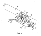
- Fig. 1 is an oblique view of a first embodiment of a shift control device 10 according to the present invention mounted to a bicycle handlebar 12;
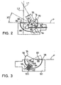
- Fig. 2 is a cut away view showing how an inner wire 14 of a Bowden-type control cable 46 is connected to shift control device 10, and
- Fig. 3 is a cut away view showing a detent mechanism 18 for shift control device 10.
- shift control device 10 is mounted adjacent to a brake control device 22 having a brake control lever 26 pivotably connected to a brake control device housing 30 for operating a Bowden-type brake control cable 32 in a well known manner.
- Brake control device housing 30 includes an attachment band 34 that substantially encircles handlebar 12 for mounting brake control device 22 to handlebar 12 inward of a grip portion 36 of handlebar 12. More specifically, a mounting bolt 38 extends through an opening (not shown) in a mounting ear 42 and screws into a threaded opening (not shown) in an opposed mounting ear 46 for drawing mounting ears 42 and 44 toward each other to tighten attachment band 34 around handlebar 12. Attachment band 34 extends along a handlebar axis H, wherein handlebar axis H is centered within attachment band 34.
- shift control device 10 is used to operate a Bowden-type control cable 46 wherein a shift control element such as inner wire 14 slides within an outer casing 48.
- Shift control device 10 includes a generally rectangular housing 50 that is attached to handlebar 12 though an attachment band 54 that has the same structure as attachment band 34 (i.e., two mounting ears tightened by a mounting bolt, not shown).
- a conventional cable adjusting barrel 58 screws into the side of housing 50 and terminates outer casing 48 of control cable 46 in a well known manner.
- a takeup element 62 ( Fig. 2 ) having a cable coupling bore 64 and a winding surface 66 is disposed in housing 50. Cable coupling bore 64 engages a conventional cable end bead 65 of inner wire 14 for pulling and releasing inner wire 14.
- Inner wire 14 slightly winds and unwinds around winding surface 66 during the pulling and releasing operations.
- a first finger contact member 70 having a first finger contact surface 74 is disposed above and faces away from a plane P which contains an upper surface 75 of housing 50.
- a second finger contact member 78 having a second finger contact surface 82 also is disposed above and faces away from plane P.
- An interconnecting member 86 is pivotably connected to housing 50 through a pivot shaft 90 so that interconnecting member 86 rotates around a rotational axis R that extends in a direction substantially perpendicular to attachment band 54 and handlebar axis H.
- interconnecting member 86 interconnects first finger contact member 70, second finger contacting member 78 and takeup element 62 so that first finger contact member 70 and second finger contact member 78 are located on opposite sides of rotational axis R and move (i.e, pivot) in a same direction relative to rotational axis R.
- first finger contact member 70 moves toward plane P (from the position indicated in solid lines in Fig. 2 to the position shown in broken lines in Fig.
- first finger contact member 70 moves away from plane P when takeup element 62 moves in a wire pulling direction
- second finger contact member 78 moves away from plane P when takeup element 62 moves in the wire pulling direction
- second finger contact member 82 moves toward plane P when takeup element 62 moves in the wire releasing direction.
- first finger contact member 70, second finger contact member 78, takeup element 62 and interconnecting member 65 in this embodiment are formed as one piece or at least integrally coupled together.
- first finger contact surface 74 is inclined relative to second finger contact surface 82 such that a first straight phantom line L1 extending upwardly and perpendicularly away first finger contact surface 74 intersects a second straight phantom line L2 extending upwardly and perpendicularly away from second finger contact surface 82, regardless of the position in which shift control device 10 is viewed.
- the resulting structure operates like a rocker switch.
- phantom lines are readily determined from the flat finger contact surfaces 74 and 82 in this embodiment, such phantom lines also can be determined easily from embodiments with no flat finger contact surfaces by drawing the phantom line perpendicular to a line that is tangent to the finger contact surface at the point of contact between the phantom line and the finger contact surface. Also, in other embodiments the intersection of the phantom lines could be located downwardly away from the finger contact surfaces.
- Fig. 3 is a cut away view showing detent mechanism 18 for shift control device 10.
- detent mechanism 18 maintains takeup element 62 in only two positions: the cable pulled position shown by broken lines in Fig. 2 and the cable released position shown by solid lines in Fig. 2 .
- Detent mechanism 18 includes a first recess 92, a second recess 94 and a detent projection 98 formed on interconnecting member 86.
- a spring 102 is disposed in a recess 104 in housing 50 for pressing a detent member 108 against interconnecting member 86.
- takeup element 62 will be maintained in the cable pulled position when detent member 108 is disposed in first recess 92, and takeup element 62 will be maintained in the cable released position when detent member 108 is disposed in second recess 94.
- no biasing mechanism is provided to bias takeup element 62, first finger contact member 70 or second finger contact member 78 toward any particular position.
- first finger contact member 70 and second finger contact member 78 are free to float in the range determined by the circumferential width of first recess 92 and second recess 94.
- a lever ratio LR A/B, wherein A is the distance between the rotational axis R and a reference line RL perpendicular to first finger contact surface 74, the distance being measured perpendicular to reference line RL, and B is the distance between the rotational axis R and the inner wire 14.
- the location ofRL is determined by adding 5 millimeters to the radius of curvature Rl (in millimeters) of the edge of first finger contact member 70.
- R1 is one millimeter, so RL is located 6 millimeters from the edge of first finger contact member 70.
- Fig. 4 is an oblique view of a shift control device 10' which represents a second embodiment of the present invention. This embodiment is constructed the same as shift control device 10 shown in Figs. 1-3 except where shown or noted. Accordingly, the same components are numbered the same.
- This shift control device 10' differs from shift control device 10 in that housing 50 extends radially outward from attachment band 54 and handlebar axis H, and rotational axis R is substantially parallel to handlebar axis H. Also, housing 50 includes a wire guide portion 120 with a cable guide surface 124 for changing the direction of inner wire 14 so that control cable 46 can extend substantially parallel to handlebar 12 in a well known manner.
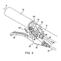
- Fig. 5 is an oblique view of a shift control device 10" which represents a third embodiment of the present invention. This embodiment is constructed the same as shift control device 10 shown in Figs. 1-3 except where shown or noted. Accordingly, the same components are numbered the same.
- This shift control device 10" differs from shift control device 10 in that a lever 140 that is integrally formed as one piece with interconnecting member 86, first finger contact member 70 and second finger contact member 74 extends outwardly from plane P between first finger contact surface 78 and second finger contact surface 82.
- shift control device 10" can operate like a rocker switch by pressing first finger contact surface 78 or second finger contact surface 82.
- shift control device 10" can operate like a toggle switch by moving lever 140.
Landscapes
- Engineering & Computer Science (AREA)
- Mechanical Engineering (AREA)
- Chemical & Material Sciences (AREA)
- Combustion & Propulsion (AREA)
- Transportation (AREA)
- Gear-Shifting Mechanisms (AREA)
- Mechanical Control Devices (AREA)
- Steering Devices For Bicycles And Motorcycles (AREA)
- Arrangement Or Mounting Of Control Devices For Change-Speed Gearing (AREA)
- Control Of Transmission Device (AREA)
Claims (14)
- Dispositif de commande de changement de vitesses pour bicyclette (10, 10', 10") comprenant:un cadre (50) comprenant une surface supérieure (75) ;un élément d'étirement (62) pour tirer et libérer un élément de commande de changement de vitesses (14);un premier élément de contact de doigt (70) comprenant une première surface de contact de doigt (74) disposée sur un premier côté d'un plan (P), dans lequel le premier élément de contact de doigt (70) se déplace vers le plan (P) lorsque l'élément d'étirement (62) se déplace dans un sens de traction, et dans lequel le premier élément de contact de doigt (70) s'éloigne du plan (P) lorsque l'élément d'étirement (62) se déplace dans un sens de relâchement; etun deuxième élément de contact de doigt (78) comprenant une deuxième surface de contact (82) disposée sur le premier côté du plan (P), dans lequel le deuxième élément de contact de doigt (78) s'éloigne du plan (P) lorsque l'élément d'étirement (62) se déplace dans le sens de traction, et dans lequel le deuxième élément de contact de doigt (78) se déplace vers le plan (P) lorsque l'élément d'étirement (62) se déplace dans le sens de relâchement;dans lequel l'élément d'étirement (62) est formé d'un seul tenant avec le premier élément de contact de doigt (70) et le deuxième élément de contact de doigt (78),
caractérisé en ce que
l'élément d'étirement (62) n'est pas sollicité lorsque l'élément d'étirement (62) est déconnecté de l'élément de commande de changement de vitesses (14), et
dans lequel le plan (P) contient la surface supérieure (75) du cadre (50). - Dispositif selon la revendication 1, comprenant en outre un élément d'interconnexion (86) qui tourne autour d'un axe de rotation, dans lequel l'élément d'interconnexion (86) relie entre eux le premier élément de contact de doigt (70) et le deuxième élément de contact de doigt (78) de sorte que le premier élément de contact de doigt (70) et le deuxième élément de contact de doigt (78) se déplacent dans le même sens par rapport à l'axe de rotation.
- Dispositif selon la revendication 2, dans lequel une première ligne imaginaire droite perpendiculaire à la première surface de contact de doigt (74) coupe une deuxième ligne imaginaire droite perpendiculaire à la deuxième surface de contact de doigt (82).
- Dispositif selon la revendication 3, dans lequel la première ligne imaginaire droite s'étend à distance du plan, et dans lequel la deuxième ligne imaginaire droite s'étend à distance du plan.
- Dispositif selon l'une quelconque des revendications 2 à 4, dans lequel le premier élément de contact de doigt (70) est d'un seul tenant avec le deuxième élément de contact de doigt (78).
- Dispositif selon l'une quelconque des revendications 2 à 5, dans lequel la première surface de contact de doigt (74) comprend une première partie plate, dans lequel la deuxième surface de contact de doigt (82) comprend une deuxième partie plate, et dans lequel la première partie plate est inclinée par rapport à la deuxième partie plate.
- Dispositif selon l'une quelconque des revendications 2 à 6, dans lequel le premier élément de contact de doigt (70) et le deuxième élément de contact de doigt (78) pivotent autour de l'axe de rotation.
- Dispositif selon l'une quelconque des revendications 2 à 7, dans lequel la première surface de contact de doigt (74) est disposée sur un premier côté de l'axe de rotation et dans lequel la deuxième surface de contact de doigt (82) est disposée sur un deuxième côté de l'axe de rotation.
- Dispositif selon l'une quelconque des revendications précédentes, dans lequel l'élément d'étirement (62), le premier élément de contact de doigt (70) et le deuxième élément de contact de doigt (78) sont une seule pièce.
- Dispositif selon l'une quelconque des revendications précédentes, comprenant en outre un mécanisme de détente (18) destiné à maintenir l'élément d'étirement (62) dans une parmi une position tirée de câble et une position relâchée de câble.
- Dispositif selon l'une quelconque des revendications précédentes, dans lequel la première surface de contact de doigt (78) et la deuxième surface de contact de doigt (82) sont opposées au plan (P).
- Dispositif selon l'une quelconque des revendications précédentes, dans lequel l'élément d'étirement (62) comprend une surface d'enroulement de câble.
- Dispositif selon l'une quelconque des revendications précédentes comprenant en outre un levier (140) s'étendant à distance du plan (P) au niveau d'un emplacement entre la première surface de contact de doigt (74) et la deuxième surface de contact de doigt (82).
- Dispositif selon l'une quelconque des revendications précédentes dans lequel un rapport de levier du dispositif de commande de changement de vitesses, qui est le rapport d'une distance entre un axe de rotation et une ligne de référence perpendiculaire à la première surface de contact de doigt (74) et une distance entre l'axe de rotation et un câble intérieur (14) d'un câble de commande (32) est inférieur à 2,0.
Priority Applications (3)
| Application Number | Priority Date | Filing Date | Title |
|---|---|---|---|
| EP05008554A EP1553016A3 (fr) | 2000-03-03 | 2001-02-02 | Manette type de dispositif de commande de changement de vitesse pour bicyclette |
| EP05008553A EP1553015A3 (fr) | 2000-03-03 | 2001-02-02 | Bouton type de dispositif de commande de changement de vitesse pour bicyclettes |
| EP05008555A EP1553017B1 (fr) | 2000-03-03 | 2001-02-02 | Bouton type de dispositif de commande de changement de vitesses pour bicyclette |
Applications Claiming Priority (2)
| Application Number | Priority Date | Filing Date | Title |
|---|---|---|---|
| US09/519,014 US6453764B1 (en) | 2000-03-03 | 2000-03-03 | Switch style bicycle shift control device |
| US519014 | 2000-03-03 |
Related Child Applications (3)
| Application Number | Title | Priority Date | Filing Date |
|---|---|---|---|
| EP05008553A Division EP1553015A3 (fr) | 2000-03-03 | 2001-02-02 | Bouton type de dispositif de commande de changement de vitesse pour bicyclettes |
| EP05008555A Division EP1553017B1 (fr) | 2000-03-03 | 2001-02-02 | Bouton type de dispositif de commande de changement de vitesses pour bicyclette |
| EP05008554A Division EP1553016A3 (fr) | 2000-03-03 | 2001-02-02 | Manette type de dispositif de commande de changement de vitesse pour bicyclette |
Publications (4)
| Publication Number | Publication Date |
|---|---|
| EP1129937A2 EP1129937A2 (fr) | 2001-09-05 |
| EP1129937A3 EP1129937A3 (fr) | 2004-03-24 |
| EP1129937B1 EP1129937B1 (fr) | 2005-11-23 |
| EP1129937B2 true EP1129937B2 (fr) | 2009-06-03 |
Family
ID=24066417
Family Applications (4)
| Application Number | Title | Priority Date | Filing Date |
|---|---|---|---|
| EP01300974A Expired - Lifetime EP1129937B2 (fr) | 2000-03-03 | 2001-02-02 | Dispositif de commande de changement de vitesses pour bicyclette |
| EP05008555A Expired - Lifetime EP1553017B1 (fr) | 2000-03-03 | 2001-02-02 | Bouton type de dispositif de commande de changement de vitesses pour bicyclette |
| EP05008554A Withdrawn EP1553016A3 (fr) | 2000-03-03 | 2001-02-02 | Manette type de dispositif de commande de changement de vitesse pour bicyclette |
| EP05008553A Withdrawn EP1553015A3 (fr) | 2000-03-03 | 2001-02-02 | Bouton type de dispositif de commande de changement de vitesse pour bicyclettes |
Family Applications After (3)
| Application Number | Title | Priority Date | Filing Date |
|---|---|---|---|
| EP05008555A Expired - Lifetime EP1553017B1 (fr) | 2000-03-03 | 2001-02-02 | Bouton type de dispositif de commande de changement de vitesses pour bicyclette |
| EP05008554A Withdrawn EP1553016A3 (fr) | 2000-03-03 | 2001-02-02 | Manette type de dispositif de commande de changement de vitesse pour bicyclette |
| EP05008553A Withdrawn EP1553015A3 (fr) | 2000-03-03 | 2001-02-02 | Bouton type de dispositif de commande de changement de vitesse pour bicyclettes |
Country Status (10)
| Country | Link |
|---|---|
| US (6) | US6453764B1 (fr) |
| EP (4) | EP1129937B2 (fr) |
| JP (3) | JP3642565B2 (fr) |
| CN (5) | CN100343118C (fr) |
| CZ (1) | CZ2001368A3 (fr) |
| DE (2) | DE60128015T2 (fr) |
| PL (1) | PL346141A1 (fr) |
| RU (1) | RU2001103783A (fr) |
| SK (1) | SK1832001A3 (fr) |
| TW (1) | TW527301B (fr) |
Families Citing this family (49)
| Publication number | Priority date | Publication date | Assignee | Title |
|---|---|---|---|---|
| ITTO20011079A1 (it) * | 2001-11-16 | 2003-05-16 | Campagnolo Srl | ,,dispositivo di comando del cambio per una bicicletta avente un manubrio con estremita' diritte,, |
| US6694840B2 (en) * | 2002-01-10 | 2004-02-24 | Shimano Inc. | Bicycle shift operating device for bicycle transmission |
| CN100352731C (zh) * | 2002-03-08 | 2007-12-05 | 株式会社岛野 | 一种自行车换档操作装置 |
| US6734376B2 (en) | 2002-06-19 | 2004-05-11 | Shimano Inc. | Electrical switch device for bicycle |
| US7194928B2 (en) * | 2003-05-30 | 2007-03-27 | Shimano Inc. | Bicycle shift operating device |
| ATE370060T1 (de) * | 2004-02-06 | 2007-09-15 | Campagnolo Srl | Betätigungsvorrichtung für steuerkabel einer fahrradgangschaltung |
| US7779724B2 (en) * | 2004-04-19 | 2010-08-24 | Shimano Inc. | Electrical bicycle shift control device |
| ITMO20040106A1 (it) * | 2004-05-06 | 2004-08-06 | L A M S R L | Comando per l'azionamento di un cambio per biciclette. |
| US20050268794A1 (en) * | 2004-06-07 | 2005-12-08 | Yuriy Nesterov | Spool rotisserie system |
| DE102004037741C5 (de) * | 2004-08-04 | 2019-07-11 | Sram Deutschland Gmbh | Triggerschalter zur Betätigung eines Getriebes an einem Fahrrad |
| US8549954B2 (en) † | 2004-09-30 | 2013-10-08 | Shimano, Inc. | Bicycle shift device having a linearly sliding shift lever operated by a pivoting interface member |
| US20070261508A1 (en) * | 2004-10-30 | 2007-11-15 | Acenbrak Steven D | Ergonomic Shifter for a Bicycle |
| US7367420B1 (en) | 2004-12-13 | 2008-05-06 | Polaris Industries Inc. | All terrain vehicle (ATV) having a rider interface for electronic or mechanical shifting |
| US20060213311A1 (en) * | 2005-03-24 | 2006-09-28 | Shimano Inc. | Bicycle control device |
| US7793751B2 (en) * | 2005-04-01 | 2010-09-14 | Honda Motor Company, Ltd. | Vehicles including control assemblies having rotatable control knobs |
| US7527137B1 (en) * | 2005-05-18 | 2009-05-05 | Calendrille Jr John L | Combination shift and brake lever arrangement for a bicycle |
| US7802489B2 (en) * | 2005-06-01 | 2010-09-28 | Shimano Inc. | Bicycle control device |
| EP1739001B1 (fr) * | 2005-06-27 | 2008-12-31 | Campagnolo Srl | Dispositif de commande pour dérailleur de bicyclette |
| JP5027999B2 (ja) * | 2005-07-08 | 2012-09-19 | キヤノン株式会社 | 記録装置およびその制御方法 |
| DE102005039109A1 (de) * | 2005-08-10 | 2007-02-15 | Gustav Magenwirth Gmbh & Co. Kg | Hebelanordnung und Bedienungseinheit für lenkergeführte Fahrzeuge |
| JP4769064B2 (ja) * | 2005-11-11 | 2011-09-07 | デルタ工業株式会社 | 自動変速機の操作入力装置 |
| EP1790564A1 (fr) * | 2005-11-24 | 2007-05-30 | Campagnolo S.r.l. | Dispositif de commande pour dérailleur de bicyclette |
| JP2009523652A (ja) * | 2006-01-23 | 2009-06-25 | カンパニョーロ・ソシエタ・ア・レスポンサビリタ・リミタータ | 自転車のディレイラ用の制御装置 |
| ATE472468T1 (de) * | 2006-02-23 | 2010-07-15 | Campagnolo Srl | Fahrradbremsekontrollvorrichtung |
| JP4191757B2 (ja) * | 2006-10-12 | 2008-12-03 | 株式会社シマノ | 自転車用変速制御装置 |
| US7779719B2 (en) * | 2006-11-22 | 2010-08-24 | Hsiu-Chih Wang | Combination of derailleur shifter and brake lever |
| ITMI20070239A1 (it) * | 2007-02-09 | 2008-08-10 | Campagnolo Srl | Dispositivo di comando per un deragliatore di bicicletta |
| ITMI20070400A1 (it) | 2007-03-01 | 2008-09-02 | Campagnolo Srl | Dispositivo di comando per bicicletta e bicicletta comprendente tale dipsositivo |
| US8065932B2 (en) * | 2007-05-16 | 2011-11-29 | Shimano Inc. | Bicycle component actuating device |
| US7806022B2 (en) | 2007-05-16 | 2010-10-05 | Shimano Inc. | Bicycle component actuating device |
| ITMI20072230A1 (it) * | 2007-11-23 | 2009-05-24 | Campagnolo Srl | Dispositivo di comando per bicicletta con manubrio ricurvo |
| US8584550B1 (en) | 2009-05-18 | 2013-11-19 | John L. Calendrille, Jr. | Shift lever arrangement for a bicycle |
| US8489277B2 (en) | 2010-04-14 | 2013-07-16 | Shimano Inc. | Electronic suspension control apparatus |
| US10207772B2 (en) | 2011-01-28 | 2019-02-19 | Paha Designs, Llc | Gear transmission and derailleur system |
| US9327792B2 (en) | 2011-01-28 | 2016-05-03 | Paha Designs, Llc | Gear transmission and derailleur system |
| US9033833B2 (en) | 2011-01-28 | 2015-05-19 | Paha Designs, Llc | Gear transmission and derailleur system |
| US9746872B2 (en) * | 2011-04-20 | 2017-08-29 | Michael Gordon Thielvoldt | Finger-operated accelerator mechanism |
| TWM424297U (en) * | 2011-08-12 | 2012-03-11 | Lee Chi Entpr Co Ltd | Control device assembly mounted on bicycle handlebar stem |
| US9651138B2 (en) | 2011-09-30 | 2017-05-16 | Mtd Products Inc. | Speed control assembly for a self-propelled walk-behind lawn mower |
| US9027434B2 (en) * | 2012-07-16 | 2015-05-12 | Sram, Llc | Two position control device |
| JP2015085854A (ja) * | 2013-10-31 | 2015-05-07 | ヤマハ発動機株式会社 | 鞍乗型車両 |
| US9950764B2 (en) | 2014-04-09 | 2018-04-24 | Shimano Inc. | Bicycle operating device |
| TWI634039B (zh) * | 2014-04-09 | 2018-09-01 | 島野股份有限公司 | 自行車操作裝置 |
| FR3046594B1 (fr) * | 2016-01-12 | 2018-02-09 | Decathlon | Dispositif de freinage pour un vehicule comportant un guidon et un cable de frein |
| US10780940B2 (en) * | 2018-01-12 | 2020-09-22 | Shimano Inc. | Human-powered vehicle control device |
| US10974787B2 (en) * | 2019-08-27 | 2021-04-13 | Royalbaby Cycle Beijing Co., Ltd. | Brake lever and bicycle using the same |
| TWM591065U (zh) * | 2019-09-25 | 2020-02-21 | 彥豪金屬工業股份有限公司 | 自行車駐車煞車機構 |
| CN112096753B (zh) * | 2020-10-21 | 2022-03-01 | 重庆远航模具有限公司 | 一种省力把手及拉索控制结构 |
| JP7414182B1 (ja) | 2023-08-28 | 2024-01-16 | Smk株式会社 | 自転車用操作装置及びその組み立て方法 |
Citations (8)
| Publication number | Priority date | Publication date | Assignee | Title |
|---|---|---|---|---|
| DE8213244U1 (de) † | 1982-05-07 | 1982-09-09 | Fichtel & Sachs Ag, 8720 Schweinfurt | Betaetigungseinrichtung fuer gangschalteinrichtung fuer ein fahrrad od.dgl. |
| FR2574364A1 (fr) † | 1984-12-10 | 1986-06-13 | Huret Et Fils | Dispositif de commande, notamment pour derailleur |
| FR2657062A1 (fr) † | 1990-01-12 | 1991-07-19 | Sachs Ind Sa | Dispositif de commande a indexation pour derailleur de cycle. |
| US5094120A (en) † | 1989-06-26 | 1992-03-10 | Maeda Industries, Ltd. | Bicycle speed change lever assembly |
| US5186071A (en) † | 1990-03-09 | 1993-02-16 | Maeda Industries, Ltd. | Bicycle speed change lever assembly |
| EP0615896A1 (fr) † | 1993-03-09 | 1994-09-21 | Shimano Inc. | Indicateur de vitesse pour bicyclette |
| US5429012A (en) † | 1992-03-23 | 1995-07-04 | Maeda Industries, Ltd | Bicycle speed change operation assembly |
| EP0609549B1 (fr) † | 1992-12-28 | 1997-03-05 | Shimano Inc. | Dispositif de changement de vitesse pour une bicyclette |
Family Cites Families (40)
| Publication number | Priority date | Publication date | Assignee | Title |
|---|---|---|---|---|
| GB279840A (en) | 1926-10-26 | 1928-05-10 | Louis Ildevert Poirmeur | Improvements in or relating to operating or controlling devices or appliances |
| DE485925C (de) | 1927-10-12 | 1929-11-06 | Ettore Caretta | Vorrichtung zur Fernuebertragung von Bewegungen mit Hilfe eines biegsamen Kabels |
| FR1253681A (fr) | 1960-04-08 | 1961-01-02 | Somagaz Sa | Perfectionnements au dispositif de commande du distributeur des appareils de chauffage et cuisinières à mazout |
| US3082642A (en) | 1961-03-13 | 1963-03-26 | Admiral Corp | Knob assembly for guided link |
| US3398600A (en) | 1966-10-10 | 1968-08-27 | Teleflex Inc | Motion transmitting remote control assembly |
| US3633437A (en) * | 1969-07-31 | 1972-01-11 | Takuo Ishida | Hand control device for speed change gear mechanism of a bicycle |
| US3766793A (en) | 1972-08-15 | 1973-10-23 | Gen Motors Corp | Transmission shift controls |
| US3965763A (en) | 1974-06-17 | 1976-06-29 | Wechsler Joseph W | Bicycle gear shift |
| US4065983A (en) | 1976-03-22 | 1978-01-03 | Maruishi Cycle Industries, Ltd. | Device for changing the gear ratio of a variable speed gear mounted to a bicycle |
| JPS53126649A (en) | 1977-04-11 | 1978-11-06 | Bridgestone Cycle Ind Co | Double gear shifting apparatus for bicycle |
| FR2399355A1 (fr) * | 1977-08-02 | 1979-03-02 | Simplex Ets | Procede et moyens de montage et de commande des changements de vitesse a la roue arriere et au pedalier sur une bicyclette ou vehicule similaire |
| JPS5457738A (en) * | 1977-10-14 | 1979-05-09 | Maeda Ind | Operating lever device of sheath transmission for bicycle |
| JPS5742158Y2 (fr) * | 1978-10-06 | 1982-09-16 | ||
| JPS5924621Y2 (ja) * | 1979-05-02 | 1984-07-20 | 株式会社シマノ | 操作レバ−装置 |
| DE2937140C2 (de) * | 1979-09-13 | 1986-08-14 | Zahnradfabrik Friedrichshafen Ag, 7990 Friedrichshafen | Schalthebelanordnung |
| FR2518951A1 (fr) * | 1981-12-30 | 1983-07-01 | Huret & Fils | Ensemble de manette et de collier, notamment pour cycle |
| JPS58224879A (ja) | 1982-06-24 | 1983-12-27 | ブリヂストンサイクル株式会社 | 自転車用多段変速切換装置の操作具 |
| US4548092A (en) | 1983-02-10 | 1985-10-22 | Strong Jr Samuel Z | Bicycle gear shift unit |
| JPS62191293A (ja) | 1986-02-14 | 1987-08-21 | マエダ工業株式会社 | 自転車用変速操作レバ−装置 |
| US4686865A (en) * | 1986-10-20 | 1987-08-18 | Efrain Rivera | Push button shift control for bicycles and the like |
| FR2644422A1 (fr) * | 1989-03-14 | 1990-09-21 | Simplex Sa | Systeme de fixation des manettes de commande d'un changement de vitesse pour cycle |
| US5023417A (en) * | 1989-10-13 | 1991-06-11 | Joseph Magiera | Switch assembly having a rocker switch connected to a remote actuator |
| JP3065655B2 (ja) * | 1990-11-13 | 2000-07-17 | 株式会社シマノ | 自転車用変速操作装置 |
| JPH04125996U (ja) * | 1991-05-01 | 1992-11-17 | マエダ工業株式会社 | 自転車用変速操作レバー装置 |
| JP2602671Y2 (ja) * | 1992-01-21 | 2000-01-24 | 株式会社シマノ | 自転車用の表示装置付き変速操作装置 |
| CN2143196Y (zh) * | 1992-12-09 | 1993-10-06 | 日驰企业股份有限公司 | 自行车变速器控制器 |
| JPH06239287A (ja) * | 1993-02-12 | 1994-08-30 | Mori San Tsuaa:Kk | 自転車用変速操作装置 |
| US5433126A (en) | 1993-05-24 | 1995-07-18 | Flex Technologies, Inc. | Rotary controlled motion transmission assembly |
| US5437206A (en) * | 1993-12-23 | 1995-08-01 | Boor; Richard G. | Rotating brake actuator |
| US5588331A (en) | 1995-03-21 | 1996-12-31 | Industrial Technology Research Institute | Rotary shifter for bicycle |
| JP3522385B2 (ja) | 1995-05-02 | 2004-04-26 | 株式会社共立 | ハンドレバー装置 |
| JP3623020B2 (ja) | 1995-08-09 | 2005-02-23 | 株式会社シマノ | 自転車用変速操作装置 |
| IT1280987B1 (it) * | 1995-10-19 | 1998-02-11 | Campagnolo Srl | Manubrio per bicicletta del tipo "mountain-bike" o simile, con dispositivo visualizzatore associato ad un comando cambio elettronico. |
| US5678455A (en) * | 1996-02-15 | 1997-10-21 | Shimano, Inc. | Bar-end shifting device |
| US5682794A (en) | 1996-06-05 | 1997-11-04 | Shimano, Inc. | Bicycle shifting control unit |
| DE19703931A1 (de) * | 1997-02-04 | 1998-08-06 | Sram De Gmbh | Schalter zur Steuerung von Fahrradgetrieben |
| JP3005204B2 (ja) | 1997-03-31 | 2000-01-31 | 株式会社シマノ | 自転車用モータ制御装置 |
| US6305237B1 (en) * | 1998-02-27 | 2001-10-23 | Shimano, Inc. | Bicycle shift control device for controlling a gas actuated shifting device |
| US6155132A (en) | 1999-01-28 | 2000-12-05 | Shimano Inc. | Shifting unit for a bicycle |
| US6223622B1 (en) * | 2000-01-21 | 2001-05-01 | L&P Property Management Company | Push button cable actuator |
-
2000
- 2000-03-03 US US09/519,014 patent/US6453764B1/en not_active Expired - Fee Related
- 2000-12-20 TW TW089127389A patent/TW527301B/zh not_active IP Right Cessation
-
2001
- 2001-01-30 CZ CZ2001368A patent/CZ2001368A3/cs unknown
- 2001-02-02 EP EP01300974A patent/EP1129937B2/fr not_active Expired - Lifetime
- 2001-02-02 DE DE60128015T patent/DE60128015T2/de not_active Expired - Fee Related
- 2001-02-02 EP EP05008555A patent/EP1553017B1/fr not_active Expired - Lifetime
- 2001-02-02 SK SK183-2001A patent/SK1832001A3/sk unknown
- 2001-02-02 DE DE60115121T patent/DE60115121T3/de not_active Expired - Fee Related
- 2001-02-02 EP EP05008554A patent/EP1553016A3/fr not_active Withdrawn
- 2001-02-02 EP EP05008553A patent/EP1553015A3/fr not_active Withdrawn
- 2001-02-06 CN CNB031311997A patent/CN100343118C/zh not_active Expired - Fee Related
- 2001-02-06 CN CNA031312004A patent/CN1515458A/zh active Pending
- 2001-02-06 CN CNB011030933A patent/CN1153720C/zh not_active Expired - Fee Related
- 2001-02-06 CN CNA031365019A patent/CN1515459A/zh active Pending
- 2001-02-06 CN CNB031311989A patent/CN1240580C/zh not_active Expired - Fee Related
- 2001-02-12 RU RU2001103783/28A patent/RU2001103783A/ru not_active Application Discontinuation
- 2001-02-27 PL PL01346141A patent/PL346141A1/xx not_active Application Discontinuation
- 2001-03-02 JP JP2001058382A patent/JP3642565B2/ja not_active Expired - Fee Related
- 2001-11-14 US US09/992,802 patent/US6564671B2/en not_active Expired - Fee Related
- 2001-11-14 US US09/992,346 patent/US6450059B1/en not_active Expired - Fee Related
- 2001-11-14 US US09/992,279 patent/US6553861B2/en not_active Expired - Fee Related
- 2001-11-14 US US09/992,597 patent/US20020035886A1/en not_active Abandoned
-
2003
- 2003-04-01 US US10/405,749 patent/US20030167870A1/en not_active Abandoned
-
2004
- 2004-01-13 JP JP2004005716A patent/JP2004106840A/ja active Pending
- 2004-09-14 JP JP2004266360A patent/JP2004359236A/ja active Pending
Patent Citations (8)
| Publication number | Priority date | Publication date | Assignee | Title |
|---|---|---|---|---|
| DE8213244U1 (de) † | 1982-05-07 | 1982-09-09 | Fichtel & Sachs Ag, 8720 Schweinfurt | Betaetigungseinrichtung fuer gangschalteinrichtung fuer ein fahrrad od.dgl. |
| FR2574364A1 (fr) † | 1984-12-10 | 1986-06-13 | Huret Et Fils | Dispositif de commande, notamment pour derailleur |
| US5094120A (en) † | 1989-06-26 | 1992-03-10 | Maeda Industries, Ltd. | Bicycle speed change lever assembly |
| FR2657062A1 (fr) † | 1990-01-12 | 1991-07-19 | Sachs Ind Sa | Dispositif de commande a indexation pour derailleur de cycle. |
| US5186071A (en) † | 1990-03-09 | 1993-02-16 | Maeda Industries, Ltd. | Bicycle speed change lever assembly |
| US5429012A (en) † | 1992-03-23 | 1995-07-04 | Maeda Industries, Ltd | Bicycle speed change operation assembly |
| EP0609549B1 (fr) † | 1992-12-28 | 1997-03-05 | Shimano Inc. | Dispositif de changement de vitesse pour une bicyclette |
| EP0615896A1 (fr) † | 1993-03-09 | 1994-09-21 | Shimano Inc. | Indicateur de vitesse pour bicyclette |
Non-Patent Citations (3)
| Title |
|---|
| "DIN 33 401" † |
| "Excerpts from "Ergonomie", published by Heinz Schmidtke, 3rd" † |
| "Excerpts from "Fahrradtechnik" by Fritz Winkler und Siegfried Rauch, 8th Edition 1993" † |
Also Published As
Similar Documents
| Publication | Publication Date | Title |
|---|---|---|
| EP1129937B2 (fr) | Dispositif de commande de changement de vitesses pour bicyclette | |
| US5481934A (en) | Bicycle speed change operation assembly | |
| US7669502B2 (en) | Shift control device for a bicycle transmission | |
| US5755139A (en) | Bicycle shift levers which surround a handlebar | |
| EP0698548A1 (fr) | Dispositif de changement de vitesses pour une bicyclette | |
| US9809278B2 (en) | Apparatus for reducing an engaging force of an engaging member | |
| JPH0141677Y2 (fr) | ||
| EP1354793A2 (fr) | Poignée pour dispositif de changement de vitesse avec actionneur de frein integré pour bicyclette | |
| EP1452433B1 (fr) | Poignée tournante pour le changement de vitesse de bicyclette | |
| WO1992019488A1 (fr) | Levier de changement de vitesse pour une bicyclette |
Legal Events
| Date | Code | Title | Description |
|---|---|---|---|
| PUAI | Public reference made under article 153(3) epc to a published international application that has entered the european phase |
Free format text: ORIGINAL CODE: 0009012 |
|
| AK | Designated contracting states |
Kind code of ref document: A2 Designated state(s): AT BE CH CY DE DK ES FI FR GB GR IE IT LI LU MC NL PT SE TR |
|
| AX | Request for extension of the european patent |
Free format text: AL;LT;LV;MK;RO;SI |
|
| PUAL | Search report despatched |
Free format text: ORIGINAL CODE: 0009013 |
|
| AK | Designated contracting states |
Kind code of ref document: A3 Designated state(s): AT BE CH CY DE DK ES FI FR GB GR IE IT LI LU MC NL PT SE TR |
|
| AX | Request for extension of the european patent |
Extension state: AL LT LV MK RO SI |
|
| 17P | Request for examination filed |
Effective date: 20040410 |
|
| 17Q | First examination report despatched |
Effective date: 20040614 |
|
| AKX | Designation fees paid |
Designated state(s): DE FR GB IE IT NL |
|
| GRAP | Despatch of communication of intention to grant a patent |
Free format text: ORIGINAL CODE: EPIDOSNIGR1 |
|
| GRAS | Grant fee paid |
Free format text: ORIGINAL CODE: EPIDOSNIGR3 |
|
| GRAA | (expected) grant |
Free format text: ORIGINAL CODE: 0009210 |
|
| AK | Designated contracting states |
Kind code of ref document: B1 Designated state(s): DE FR GB IE IT NL |
|
| REG | Reference to a national code |
Ref country code: GB Ref legal event code: FG4D |
|
| REF | Corresponds to: |
Ref document number: 60115121 Country of ref document: DE Date of ref document: 20051229 Kind code of ref document: P |
|
| REG | Reference to a national code |
Ref country code: IE Ref legal event code: FG4D |
|
| PG25 | Lapsed in a contracting state [announced via postgrant information from national office to epo] |
Ref country code: IE Free format text: LAPSE BECAUSE OF NON-PAYMENT OF DUE FEES Effective date: 20060202 |
|
| RAP2 | Party data changed (patent owner data changed or rights of a patent transferred) |
Owner name: SHIMANO INC. |
|
| ET | Fr: translation filed | ||
| PLBI | Opposition filed |
Free format text: ORIGINAL CODE: 0009260 |
|
| PLAX | Notice of opposition and request to file observation + time limit sent |
Free format text: ORIGINAL CODE: EPIDOSNOBS2 |
|
| NLT2 | Nl: modifications (of names), taken from the european patent patent bulletin |
Owner name: SHIMANO INC. Effective date: 20060802 |
|
| 26 | Opposition filed |
Opponent name: SRAM DEUTSCHLAND GMBH Effective date: 20060822 |
|
| REG | Reference to a national code |
Ref country code: IE Ref legal event code: MM4A |
|
| NLR1 | Nl: opposition has been filed with the epo |
Opponent name: SRAM DEUTSCHLAND GMBH |
|
| PGFP | Annual fee paid to national office [announced via postgrant information from national office to epo] |
Ref country code: NL Payment date: 20070215 Year of fee payment: 7 |
|
| PLAF | Information modified related to communication of a notice of opposition and request to file observations + time limit |
Free format text: ORIGINAL CODE: EPIDOSCOBS2 |
|
| PLBB | Reply of patent proprietor to notice(s) of opposition received |
Free format text: ORIGINAL CODE: EPIDOSNOBS3 |
|
| GBPC | Gb: european patent ceased through non-payment of renewal fee |
Effective date: 20070202 |
|
| PG25 | Lapsed in a contracting state [announced via postgrant information from national office to epo] |
Ref country code: GB Free format text: LAPSE BECAUSE OF NON-PAYMENT OF DUE FEES Effective date: 20070202 |
|
| PGFP | Annual fee paid to national office [announced via postgrant information from national office to epo] |
Ref country code: GB Payment date: 20060113 Year of fee payment: 6 |
|
| NLV4 | Nl: lapsed or anulled due to non-payment of the annual fee |
Effective date: 20080901 |
|
| PG25 | Lapsed in a contracting state [announced via postgrant information from national office to epo] |
Ref country code: NL Free format text: LAPSE BECAUSE OF NON-PAYMENT OF DUE FEES Effective date: 20080901 |
|
| PUAH | Patent maintained in amended form |
Free format text: ORIGINAL CODE: 0009272 |
|
| STAA | Information on the status of an ep patent application or granted ep patent |
Free format text: STATUS: PATENT MAINTAINED AS AMENDED |
|
| PGFP | Annual fee paid to national office [announced via postgrant information from national office to epo] |
Ref country code: DE Payment date: 20090129 Year of fee payment: 9 |
|
| 27A | Patent maintained in amended form |
Effective date: 20090603 |
|
| AK | Designated contracting states |
Kind code of ref document: B2 Designated state(s): DE FR GB IE IT NL |
|
| PGFP | Annual fee paid to national office [announced via postgrant information from national office to epo] |
Ref country code: IT Payment date: 20090212 Year of fee payment: 9 |
|
| PGFP | Annual fee paid to national office [announced via postgrant information from national office to epo] |
Ref country code: FR Payment date: 20090213 Year of fee payment: 9 |
|
| PG25 | Lapsed in a contracting state [announced via postgrant information from national office to epo] |
Ref country code: DE Free format text: LAPSE BECAUSE OF NON-PAYMENT OF DUE FEES Effective date: 20100901 |
|
| PG25 | Lapsed in a contracting state [announced via postgrant information from national office to epo] |
Ref country code: IT Free format text: LAPSE BECAUSE OF NON-PAYMENT OF DUE FEES Effective date: 20100202 |
|
| REG | Reference to a national code |
Ref country code: FR Ref legal event code: ST Effective date: 20110729 |
|
| PG25 | Lapsed in a contracting state [announced via postgrant information from national office to epo] |
Ref country code: FR Free format text: LAPSE BECAUSE OF NON-PAYMENT OF DUE FEES Effective date: 20100301 |