EP1129877A1 - Seitenaufprallschutz - Google Patents
Seitenaufprallschutz Download PDFInfo
- Publication number
- EP1129877A1 EP1129877A1 EP01104863A EP01104863A EP1129877A1 EP 1129877 A1 EP1129877 A1 EP 1129877A1 EP 01104863 A EP01104863 A EP 01104863A EP 01104863 A EP01104863 A EP 01104863A EP 1129877 A1 EP1129877 A1 EP 1129877A1
- Authority
- EP
- European Patent Office
- Prior art keywords
- side impact
- impact protection
- impact beam
- profile
- bowden
- Prior art date
- Legal status (The legal status is an assumption and is not a legal conclusion. Google has not performed a legal analysis and makes no representation as to the accuracy of the status listed.)
- Granted
Links
- 229910000831 Steel Inorganic materials 0.000 claims abstract description 4
- 229910052782 aluminium Inorganic materials 0.000 claims abstract description 4
- XAGFODPZIPBFFR-UHFFFAOYSA-N aluminium Chemical compound [Al] XAGFODPZIPBFFR-UHFFFAOYSA-N 0.000 claims abstract description 4
- 239000010959 steel Substances 0.000 claims abstract description 4
- 239000004411 aluminium Substances 0.000 abstract 1
- 238000005265 energy consumption Methods 0.000 description 1
- 229910052751 metal Inorganic materials 0.000 description 1
- 239000002184 metal Substances 0.000 description 1
- 230000035515 penetration Effects 0.000 description 1
Images


Classifications
-
- B—PERFORMING OPERATIONS; TRANSPORTING
- B60—VEHICLES IN GENERAL
- B60J—WINDOWS, WINDSCREENS, NON-FIXED ROOFS, DOORS, OR SIMILAR DEVICES FOR VEHICLES; REMOVABLE EXTERNAL PROTECTIVE COVERINGS SPECIALLY ADAPTED FOR VEHICLES
- B60J5/00—Doors
- B60J5/04—Doors arranged at the vehicle sides
- B60J5/042—Reinforcement elements
- B60J5/0422—Elongated type elements, e.g. beams, cables, belts or wires
- B60J5/0423—Elongated type elements, e.g. beams, cables, belts or wires characterised by position in the lower door structure
- B60J5/0425—Elongated type elements, e.g. beams, cables, belts or wires characterised by position in the lower door structure the elements being arranged essentially horizontal in the centre of the lower door structure
-
- B—PERFORMING OPERATIONS; TRANSPORTING
- B60—VEHICLES IN GENERAL
- B60J—WINDOWS, WINDSCREENS, NON-FIXED ROOFS, DOORS, OR SIMILAR DEVICES FOR VEHICLES; REMOVABLE EXTERNAL PROTECTIVE COVERINGS SPECIALLY ADAPTED FOR VEHICLES
- B60J5/00—Doors
- B60J5/04—Doors arranged at the vehicle sides
- B60J5/042—Reinforcement elements
- B60J5/0422—Elongated type elements, e.g. beams, cables, belts or wires
- B60J5/0438—Elongated type elements, e.g. beams, cables, belts or wires characterised by the type of elongated elements
- B60J5/044—Elongated type elements, e.g. beams, cables, belts or wires characterised by the type of elongated elements the elements being flexible, e.g. belts, cables or wires
-
- B—PERFORMING OPERATIONS; TRANSPORTING
- B60—VEHICLES IN GENERAL
- B60J—WINDOWS, WINDSCREENS, NON-FIXED ROOFS, DOORS, OR SIMILAR DEVICES FOR VEHICLES; REMOVABLE EXTERNAL PROTECTIVE COVERINGS SPECIALLY ADAPTED FOR VEHICLES
- B60J5/00—Doors
- B60J5/04—Doors arranged at the vehicle sides
- B60J5/042—Reinforcement elements
- B60J5/0422—Elongated type elements, e.g. beams, cables, belts or wires
- B60J5/0438—Elongated type elements, e.g. beams, cables, belts or wires characterised by the type of elongated elements
- B60J5/0443—Beams
- B60J5/0444—Beams characterised by a special cross section
Definitions
- the invention relates to side impact protection for a vehicle, in particular a Motor vehicle, in particular a vehicle or motor vehicle door, with a Side impact beam.
- Side impact beams are used to protect the occupants of motor vehicles, in the side wall of the motor vehicle, generally in the door of a Motor vehicle, are installed.
- the object of the invention is to propose an improved side impact protection.
- the side impact protection includes a Bowden cable that is at an angle to the side impact beam runs. In the event of an impact, the side wall or the door deformed inwards. This puts the Bowden cable under tension. A large part of the impact energy can be absorbed by the Bowden cable become.
- the side impact beam has a profile with one or more Has side walls. It is advantageous if the Bowden cable or cables are guided through one or more side walls of the side impact beam. It is however, it is also possible to have the Bowden cables or cables on the underside of the or to carry the carrier.
- the profile is preferably a U-profile.
- Advantageous alternatives for this are tubular profiles or hollow chamber profiles.
- the profiles are preferred made of aluminum or steel.
- the invention further relates to a vehicle or a vehicle door by a side impact protection according to the invention are characterized.
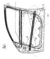
- the motor vehicle door shown in Fig. 1 consists of a door box 1, in the one Door frame 2 is screwed in. With the door box 1 is a side impact beam 3 connected, which runs essentially horizontally, but slightly from the front is inclined upwards backwards downwards.
- Bowden cables 4, 5 In the door box there are two Bowden cables 4, 5, each at an angle run to the side impact beam 3.
- the Bowden cables 4, 5 are arranged in an X-shape, their crossing point is in the area of the side impact beam 3.
- she can consist of ropes, for example wire ropes, but they can can also be realized as rods, preferably made of metal.
- the Bowden cables 4, 5 are connected to the door box 1.
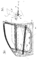
- a connection possibility is shown in Fig. 2.
- the Bowden cable 4 with one at its end located eyelet 6 in a projection 7 which is provided on a hinge 8 is that is pivotable about a horizontal axis 9.
- the side impact beam 3 is in the manner shown in FIG. 3 within the Outer skin 10 of the motor vehicle door is arranged. It has a U-shaped profile which is shown in cross section in FIG. 4 and which consists of the side parts 11 and 12 as well as the base 13. The base 13 faces the outer skin 10.
- the Side parts 11 and 12 are holes 14 through which the Bowden cables 4, 5th can step through.
- the Bowden cables 4, 5 are through the side parts 11, 12 of the U-profile of the side impact beam 3 performed.
- the invention provides a side impact beam with Bowden cables that the occupants of a vehicle, in particular a motor vehicle, in the case of a Side impact or "side impact" protects.
- a particular advantage is that an extremely space-saving arrangement is possible. In the event of a side impact the depth of penetration in the door to the vehicle compartment is reduced.
- 6-point connection can the energy consumption and - distribution can be optimized.
- the side impact beam has a hollow chamber profile, which consists of the side parts 11 'and 12' and the base parts 13 'and 15.
- the base parts 13 'and 15 each project laterally beyond the side parts 11 'and 12'.
- a pipe profile could also be used.
- the profiles are preferably in Made of aluminum or steel.
Landscapes
- Engineering & Computer Science (AREA)
- Mechanical Engineering (AREA)
- Body Structure For Vehicles (AREA)
- Lock And Its Accessories (AREA)
Abstract
Description
- Fig. 1
- eine Kraftfahrzeugtüre in einer Seitenansicht,
- Fig. 2
- einen Anlenkpunkt eines Bowdenzuges in einer vergrößerten Darstellung,
- Fig. 3
- die Fahrzeugtüre gemäß Fig. 1 in einer Ansicht von oben,
- Fig. 4
- einen Schnitt längs der Linie A-A in Fig. 3 und
- Fig. 5
- eine alternative Querschnittsform für das Profil des Seitenaufprallträgers.
Claims (6)
- Seitenaufprallschutz für ein Fahrzeug, insbesondere für eine Fahrzeugtüre, mit einem Seitenaufprallträger (3),
gekennzeichnet durch
einen Bowdenzug (4, 5), der in einem Winkel zum Seitenaufprallträger (3) verläuft. - Seitenaufprallschutz nach Anspruch 1, dadurch gekennzeichnet, daß zwei Bowdenzüge (4, 5) vorhanden sind.
- Seitenaufprallschutz nach Anspruch 2, dadurch gekennzeichnet, daß sich die Bowdenzüge (4, 5) kreuzen.
- Seitenaufprallschutz nach einem vorhergehenden Ansprüche, dadurch gekenn-zeichnet, daß der Seitenaufprallträger (3) ein U-Profil oder ein Rohrprofil oder ein Hohlkammerprofil aufweist, die vorzugsweise in Stahl oder Aluminium aus-geführt sind.
- Seitenaufprallschutz nach Anspruch 4, dadurch gekennzeichnet, daß der bzw. die Bowdenzüge (4, 5) durch die Seitenwand bzw. Seitenwände des Seitenaufprallträgers (3) geführt sind und/oder daß der bzw. die Bowdenzüge (4, 5) an der Unterseite des Seitenaufprallträgers (3) geführt sind.
- Fahrzeug oder Fahrzeugtüre, gekennzeichnet durch einen Seitenaufprallschutz nach einem der Ansprüche 1 bis 5.
Applications Claiming Priority (2)
| Application Number | Priority Date | Filing Date | Title |
|---|---|---|---|
| DE10009675 | 2000-02-29 | ||
| DE2000109675 DE10009675B4 (de) | 2000-02-29 | 2000-02-29 | Seitenaufprallschutz |
Publications (2)
| Publication Number | Publication Date |
|---|---|
| EP1129877A1 true EP1129877A1 (de) | 2001-09-05 |
| EP1129877B1 EP1129877B1 (de) | 2007-09-19 |
Family
ID=7632915
Family Applications (1)
| Application Number | Title | Priority Date | Filing Date |
|---|---|---|---|
| EP20010104863 Expired - Lifetime EP1129877B1 (de) | 2000-02-29 | 2001-02-28 | Seitenaufprallschutz |
Country Status (2)
| Country | Link |
|---|---|
| EP (1) | EP1129877B1 (de) |
| DE (2) | DE10009675B4 (de) |
Cited By (2)
| Publication number | Priority date | Publication date | Assignee | Title |
|---|---|---|---|---|
| WO2003059669A1 (en) * | 2002-01-16 | 2003-07-24 | Honda Giken Kogyo Kabushiki Kaisha | Vehicle door |
| US9950594B1 (en) | 2017-03-09 | 2018-04-24 | Ford Global Technologies, Llc | Impact absorbing system for a vehicle |
Families Citing this family (3)
| Publication number | Priority date | Publication date | Assignee | Title |
|---|---|---|---|---|
| DE102006023922B4 (de) * | 2006-05-19 | 2010-01-07 | Ise Automotive Gmbh | Vorrichtung zum Seitenaufprallschutz |
| DE102008006396A1 (de) * | 2008-01-28 | 2009-07-30 | Dirk Schroer | Crashschutz für Kraftfahrzeuge, insbesondere für Kraftfahrzeugtüren |
| DE102009023678A1 (de) * | 2009-06-03 | 2011-02-03 | Benteler Automobiltechnik Gmbh | Anordnung zur Verstärkung eines Bauteils einer Kraftfahrzeugkarosserie |
Citations (6)
| Publication number | Priority date | Publication date | Assignee | Title |
|---|---|---|---|---|
| US5221121A (en) * | 1990-10-04 | 1993-06-22 | Mannesmann Aktiengesellschaft | Reinforcement element for the body of an automobile |
| DE4337082A1 (de) * | 1992-10-30 | 1994-05-05 | Nissan Motor | Fahrzeugkarosserie |
| DE4423741A1 (de) * | 1994-07-06 | 1996-01-18 | Bayerische Motoren Werke Ag | Seitenaufprallschutz für die Tür eines Fahrzeuges |
| DE19633637A1 (de) * | 1996-08-21 | 1998-02-26 | Oehme Metallbearbeitung Kg | Fahrzeugtür mit Seitenaufprallschutz |
| DE19756459A1 (de) * | 1997-11-25 | 1999-06-02 | Wagon Automotive Gmbh | Aufprallträger für eine Kraftfahrzeugtür |
| DE19914344A1 (de) * | 1998-04-01 | 1999-11-25 | Fraunhofer Ges Forschung | Tragstruktur, insbesondere Seitenaufprallträger für Fahrzeuge |
Family Cites Families (1)
| Publication number | Priority date | Publication date | Assignee | Title |
|---|---|---|---|---|
| DE19927926C2 (de) * | 1999-06-18 | 2003-05-28 | Daimler Chrysler Ag | Kraftfahrzeugtür |
-
2000
- 2000-02-29 DE DE2000109675 patent/DE10009675B4/de not_active Expired - Fee Related
-
2001
- 2001-02-28 DE DE50113022T patent/DE50113022D1/de not_active Expired - Lifetime
- 2001-02-28 EP EP20010104863 patent/EP1129877B1/de not_active Expired - Lifetime
Patent Citations (6)
| Publication number | Priority date | Publication date | Assignee | Title |
|---|---|---|---|---|
| US5221121A (en) * | 1990-10-04 | 1993-06-22 | Mannesmann Aktiengesellschaft | Reinforcement element for the body of an automobile |
| DE4337082A1 (de) * | 1992-10-30 | 1994-05-05 | Nissan Motor | Fahrzeugkarosserie |
| DE4423741A1 (de) * | 1994-07-06 | 1996-01-18 | Bayerische Motoren Werke Ag | Seitenaufprallschutz für die Tür eines Fahrzeuges |
| DE19633637A1 (de) * | 1996-08-21 | 1998-02-26 | Oehme Metallbearbeitung Kg | Fahrzeugtür mit Seitenaufprallschutz |
| DE19756459A1 (de) * | 1997-11-25 | 1999-06-02 | Wagon Automotive Gmbh | Aufprallträger für eine Kraftfahrzeugtür |
| DE19914344A1 (de) * | 1998-04-01 | 1999-11-25 | Fraunhofer Ges Forschung | Tragstruktur, insbesondere Seitenaufprallträger für Fahrzeuge |
Cited By (4)
| Publication number | Priority date | Publication date | Assignee | Title |
|---|---|---|---|---|
| WO2003059669A1 (en) * | 2002-01-16 | 2003-07-24 | Honda Giken Kogyo Kabushiki Kaisha | Vehicle door |
| US6969107B2 (en) | 2002-01-16 | 2005-11-29 | Honda Giken Kogyo Kabushiki Kaisha | Vehicle door |
| CN1319768C (zh) * | 2002-01-16 | 2007-06-06 | 本田技研工业株式会社 | 车门 |
| US9950594B1 (en) | 2017-03-09 | 2018-04-24 | Ford Global Technologies, Llc | Impact absorbing system for a vehicle |
Also Published As
| Publication number | Publication date |
|---|---|
| EP1129877B1 (de) | 2007-09-19 |
| DE10009675B4 (de) | 2004-10-28 |
| DE10009675A1 (de) | 2001-09-13 |
| DE50113022D1 (de) | 2007-10-31 |
Similar Documents
| Publication | Publication Date | Title |
|---|---|---|
| DE69819570T2 (de) | Fahrzeugaufbaukonstruktion | |
| DE19538229B4 (de) | Obere Karosseriestruktur für Fahrzeugkarosserien | |
| EP0274985B1 (de) | Fahrzeugtüre | |
| EP0561834A1 (de) | Kraftfahrzeug mit einer durch ein strangpressprofil gebildeten mittelsäule. | |
| DE102016212297B4 (de) | Kraftfahrzeug | |
| DE102014108958B4 (de) | Doppelfunktionsschweller und Sitzverstärkung | |
| DE102005029255B4 (de) | Schwelleranordnung für ein Fahrzeug | |
| DE2536820C2 (de) | ||
| DE2759029C2 (de) | ||
| DE19514022C1 (de) | Hardtop-Fahrzeug | |
| DE2638440B2 (de) | Ueberschlagschutzrahmen fuer kraftfahrzeuge | |
| DE10339307B3 (de) | Aufprallschutzvorrichtung für eine Tür eines Kraftfahrzeugs | |
| EP1129877A1 (de) | Seitenaufprallschutz | |
| DE29613472U1 (de) | Fahrzeugtür | |
| DE10302756B4 (de) | Tragstruktur für eine Kraftwagenkarosserie | |
| DE69714465T2 (de) | Omnibus mit sicherheitsvorrichtungen wie eine überrollvorrichtung, sowie verfahren zum zusammenbau eines omnibuses | |
| EP1116641A2 (de) | Karosserievorderbau für ein Kraftfahrzeug | |
| DE19732700B4 (de) | Rahmenanordnung für ein Deckelteil eines Fahrzeugdaches | |
| DE4139305A1 (de) | Tuersaeule an einer karosserie eines personenkraftwagens | |
| DE2046996C3 (de) | Führung für starre Schiebedächer bei Kraftfahrzeugen | |
| EP1194359B1 (de) | Seilzug-aufzuganlage | |
| DE19538457A1 (de) | Mehrkammerprofil | |
| DE2420248A1 (de) | Universalrichtgeraet | |
| DE10023571B4 (de) | Wärmetauscheranordnung an einer vorderen Tragstruktur eines Kraftwagens | |
| DE19829832A1 (de) | Karosseriestruktur für ein Kraftfahrzeug |
Legal Events
| Date | Code | Title | Description |
|---|---|---|---|
| PUAI | Public reference made under article 153(3) epc to a published international application that has entered the european phase |
Free format text: ORIGINAL CODE: 0009012 |
|
| AK | Designated contracting states |
Kind code of ref document: A1 Designated state(s): AT BE CH CY DE DK ES FI FR GB GR IE IT LI LU MC NL PT SE TR Kind code of ref document: A1 Designated state(s): DE FR GB IT |
|
| AX | Request for extension of the european patent |
Free format text: AL;LT;LV;MK;RO;SI |
|
| 17P | Request for examination filed |
Effective date: 20011113 |
|
| AKX | Designation fees paid |
Free format text: DE FR GB IT |
|
| 17Q | First examination report despatched |
Effective date: 20060915 |
|
| GRAP | Despatch of communication of intention to grant a patent |
Free format text: ORIGINAL CODE: EPIDOSNIGR1 |
|
| GRAS | Grant fee paid |
Free format text: ORIGINAL CODE: EPIDOSNIGR3 |
|
| GRAA | (expected) grant |
Free format text: ORIGINAL CODE: 0009210 |
|
| AK | Designated contracting states |
Kind code of ref document: B1 Designated state(s): DE FR GB IT |
|
| REG | Reference to a national code |
Ref country code: GB Ref legal event code: FG4D Free format text: NOT ENGLISH |
|
| REF | Corresponds to: |
Ref document number: 50113022 Country of ref document: DE Date of ref document: 20071031 Kind code of ref document: P |
|
| GBT | Gb: translation of ep patent filed (gb section 77(6)(a)/1977) |
Effective date: 20071206 |
|
| ET | Fr: translation filed | ||
| PLBE | No opposition filed within time limit |
Free format text: ORIGINAL CODE: 0009261 |
|
| STAA | Information on the status of an ep patent application or granted ep patent |
Free format text: STATUS: NO OPPOSITION FILED WITHIN TIME LIMIT |
|
| 26N | No opposition filed |
Effective date: 20080620 |
|
| PGFP | Annual fee paid to national office [announced via postgrant information from national office to epo] |
Ref country code: FR Payment date: 20100519 Year of fee payment: 10 |
|
| PGFP | Annual fee paid to national office [announced via postgrant information from national office to epo] |
Ref country code: GB Payment date: 20100429 Year of fee payment: 10 |
|
| PG25 | Lapsed in a contracting state [announced via postgrant information from national office to epo] |
Ref country code: IT Free format text: LAPSE BECAUSE OF NON-PAYMENT OF DUE FEES Effective date: 20080229 |
|
| GBPC | Gb: european patent ceased through non-payment of renewal fee |
Effective date: 20110228 |
|
| REG | Reference to a national code |
Ref country code: FR Ref legal event code: ST Effective date: 20111102 |
|
| PG25 | Lapsed in a contracting state [announced via postgrant information from national office to epo] |
Ref country code: FR Free format text: LAPSE BECAUSE OF NON-PAYMENT OF DUE FEES Effective date: 20110228 |
|
| PG25 | Lapsed in a contracting state [announced via postgrant information from national office to epo] |
Ref country code: GB Free format text: LAPSE BECAUSE OF NON-PAYMENT OF DUE FEES Effective date: 20110228 |
|
| PGFP | Annual fee paid to national office [announced via postgrant information from national office to epo] |
Ref country code: DE Payment date: 20120228 Year of fee payment: 12 |
|
| REG | Reference to a national code |
Ref country code: DE Ref legal event code: R119 Ref document number: 50113022 Country of ref document: DE Effective date: 20130903 |
|
| PG25 | Lapsed in a contracting state [announced via postgrant information from national office to epo] |
Ref country code: DE Free format text: LAPSE BECAUSE OF NON-PAYMENT OF DUE FEES Effective date: 20130903 |