EP1128102B1 - Ventil mit Kupplungselementen - Google Patents
Ventil mit Kupplungselementen Download PDFInfo
- Publication number
- EP1128102B1 EP1128102B1 EP01103922A EP01103922A EP1128102B1 EP 1128102 B1 EP1128102 B1 EP 1128102B1 EP 01103922 A EP01103922 A EP 01103922A EP 01103922 A EP01103922 A EP 01103922A EP 1128102 B1 EP1128102 B1 EP 1128102B1
- Authority
- EP
- European Patent Office
- Prior art keywords
- valve
- connexion
- groove
- securing means
- spring
- Prior art date
- Legal status (The legal status is an assumption and is not a legal conclusion. Google has not performed a legal analysis and makes no representation as to the accuracy of the status listed.)
- Expired - Lifetime
Links
- 230000008878 coupling Effects 0.000 title claims description 12
- 238000010168 coupling process Methods 0.000 title claims description 12
- 238000005859 coupling reaction Methods 0.000 title claims description 12
- 230000002093 peripheral effect Effects 0.000 claims 5
- 238000007789 sealing Methods 0.000 description 4
- 230000015572 biosynthetic process Effects 0.000 description 3
- 238000009434 installation Methods 0.000 description 2
- 238000012549 training Methods 0.000 description 2
- 230000000903 blocking effect Effects 0.000 description 1
- 238000011161 development Methods 0.000 description 1
- 230000018109 developmental process Effects 0.000 description 1
- 238000005516 engineering process Methods 0.000 description 1
- 210000003746 feather Anatomy 0.000 description 1
- 238000002347 injection Methods 0.000 description 1
- 239000007924 injection Substances 0.000 description 1
- 239000000243 solution Substances 0.000 description 1
- 239000000725 suspension Substances 0.000 description 1
- 230000007704 transition Effects 0.000 description 1
Images

Classifications
-
- F—MECHANICAL ENGINEERING; LIGHTING; HEATING; WEAPONS; BLASTING
- F16—ENGINEERING ELEMENTS AND UNITS; GENERAL MEASURES FOR PRODUCING AND MAINTAINING EFFECTIVE FUNCTIONING OF MACHINES OR INSTALLATIONS; THERMAL INSULATION IN GENERAL
- F16K—VALVES; TAPS; COCKS; ACTUATING-FLOATS; DEVICES FOR VENTING OR AERATING
- F16K1/00—Lift valves or globe valves, i.e. cut-off apparatus with closure members having at least a component of their opening and closing motion perpendicular to the closing faces
- F16K1/30—Lift valves or globe valves, i.e. cut-off apparatus with closure members having at least a component of their opening and closing motion perpendicular to the closing faces specially adapted for pressure containers
- F16K1/301—Lift valves or globe valves, i.e. cut-off apparatus with closure members having at least a component of their opening and closing motion perpendicular to the closing faces specially adapted for pressure containers only shut-off valves, i.e. valves without additional means
- F16K1/303—Lift valves or globe valves, i.e. cut-off apparatus with closure members having at least a component of their opening and closing motion perpendicular to the closing faces specially adapted for pressure containers only shut-off valves, i.e. valves without additional means with a valve member, e.g. stem or shaft, passing through the seat
-
- F—MECHANICAL ENGINEERING; LIGHTING; HEATING; WEAPONS; BLASTING
- F16—ENGINEERING ELEMENTS AND UNITS; GENERAL MEASURES FOR PRODUCING AND MAINTAINING EFFECTIVE FUNCTIONING OF MACHINES OR INSTALLATIONS; THERMAL INSULATION IN GENERAL
- F16K—VALVES; TAPS; COCKS; ACTUATING-FLOATS; DEVICES FOR VENTING OR AERATING
- F16K1/00—Lift valves or globe valves, i.e. cut-off apparatus with closure members having at least a component of their opening and closing motion perpendicular to the closing faces
- F16K1/30—Lift valves or globe valves, i.e. cut-off apparatus with closure members having at least a component of their opening and closing motion perpendicular to the closing faces specially adapted for pressure containers
- F16K1/304—Shut-off valves with additional means
- F16K1/306—Shut-off valves with additional means with a valve member, e.g. stem or shaft, passing through the seat
-
- F—MECHANICAL ENGINEERING; LIGHTING; HEATING; WEAPONS; BLASTING
- F16—ENGINEERING ELEMENTS AND UNITS; GENERAL MEASURES FOR PRODUCING AND MAINTAINING EFFECTIVE FUNCTIONING OF MACHINES OR INSTALLATIONS; THERMAL INSULATION IN GENERAL
- F16K—VALVES; TAPS; COCKS; ACTUATING-FLOATS; DEVICES FOR VENTING OR AERATING
- F16K1/00—Lift valves or globe valves, i.e. cut-off apparatus with closure members having at least a component of their opening and closing motion perpendicular to the closing faces
- F16K1/30—Lift valves or globe valves, i.e. cut-off apparatus with closure members having at least a component of their opening and closing motion perpendicular to the closing faces specially adapted for pressure containers
- F16K1/307—Additional means used in combination with the main valve
-
- F—MECHANICAL ENGINEERING; LIGHTING; HEATING; WEAPONS; BLASTING
- F16—ENGINEERING ELEMENTS AND UNITS; GENERAL MEASURES FOR PRODUCING AND MAINTAINING EFFECTIVE FUNCTIONING OF MACHINES OR INSTALLATIONS; THERMAL INSULATION IN GENERAL
- F16K—VALVES; TAPS; COCKS; ACTUATING-FLOATS; DEVICES FOR VENTING OR AERATING
- F16K1/00—Lift valves or globe valves, i.e. cut-off apparatus with closure members having at least a component of their opening and closing motion perpendicular to the closing faces
- F16K1/30—Lift valves or globe valves, i.e. cut-off apparatus with closure members having at least a component of their opening and closing motion perpendicular to the closing faces specially adapted for pressure containers
- F16K1/308—Connecting means
Definitions
- the invention relates to a valve with coupling elements for connecting parts on a gas-carrying Housing, especially with low gas pressure, according to the 1st claim and use for this.
- valves There are different designs of a valve, in which a tubular one Valve socket with a cylindrical receiving opening for a connecting part and the valve connector can be screwed onto the housing in a gas-tight manner. There is a spring loaded in the valve socket Closing insert arranged as a blocking member, which is not actuated the flow path closes. An actuating element for the locking insert is formed on the connecting part, which opens the valve path after attaching the connector.
- connecting couplings are complex designs of the coupling elements for connection bodies.
- DE-OS 30 36 141 the connector secured with a hollow cylindrical collet, the inside diameter adapted to the diameter of the cylindrical pipe socket of the valve socket is and is movable over it.
- the coupling elements are in the mentioned Fonts constructed unnecessarily complex.
- Gas-insulated switchgear - for that Valve is preferably designed - get fillings (for example with SF6) to at most a pressure of 1 bar.
- DE 42 is used as an example of a switchgear with SF6 gas tank 10 773 A1.
- US 4,009,896 A quick coupling for pipe elements is described in US 4,009,896. It is a screw-in base shown with a cylindrical bore for receiving of a connector. There is a cap over the outer cylinder of the base piece attachable, which fixes a hollow cylindrical connector. There is a rectangular one at the base There is a circumferential groove for the engagement of a position securing means for the connecting part, which passes through the outer surface of the cap.
- the base piece of the US 4,009,896 corresponds to the valve neck of this application.
- the subject matter of the invention has a number of advantages.
- the connecting parts can be attached and detached without screwing tools. This is the case with large quantities noticeable that need to be evacuated and filled with gas.
- Position securing means is equipped with an outwardly widening profile.
- the depth of the groove is preferably rectangular; at least one outer edge of the groove is at Transition to the cylinder surface beveled conically; alternatively, the groove can face outwards be rectangular expanded.
- the connecting part can be placed in a gas-tight manner, therefore there is a gas-sealing element, for example an O-ring lying in a groove.
- a gas-sealing element for example an O-ring lying in a groove.
- To secure the seat of the A cylindrical cap is used on the connecting piece on the valve connector Includes means for securing the position of the valve nozzle.
- the means of securing the position of the The connecting part can be designed as a tension spring or as a locking bolt.
- Tension spring or Locking pins engage (at least) one groove in the cap in an appropriate position Groove in the connector.
- the locking pin is preferably spring-loaded and formed with a cylindrical shaft.
- the diameter of the cylindrical shaft corresponds to the (conical or rectangular) Widening of the ring groove.
- the dimensions of the position securing means are chosen such that they are applied or applied Removal is easy by hand, or only with the use of a simple peeling tool.
- the annular groove of the valve socket has a widening, which enables use different means of securing the position, which differ in their dimensions.
- a first position securing means for example a spring clip
- a second position securing device with a larger diameter e.g. a different spring clip or a bolt
- the cylindrical bore of the valve stub is one for receiving the cylinder pin formed by several possible connecting parts.
- the cylindrical bore has a relative one smooth surface. Connection parts with a suitable outside diameter are inserted into the hole introduced and secured by a means of security - as mentioned above.
- a means of security - as mentioned above.
- In the cylinder bore it is possible to twist the connector.
- a manometer to secure against accidental rotation should be in the cylinder bolt at least one O-ring of the connecting part. With this measure ensures that the position of the connector in relation to the housing, for example no longer changed by vibrations. This keeps the connector part installation position once specified.
- the closing insert is for high flow speed (with small flow resistance) of the gas shaped.
- the closing insert is acted on by a conical spring.
- the Taper spring engages around the gas-filled cylindrical shaft of the locking insert.
- the conical spring In order to the locking insert and the conical spring work together in such a way that the conical spring also operates the locking insert is centered by a connecting part. The flow path of the gas runs around the locking insert, which is held in suspension by the conical spring becomes.
- the valve should preferably be in each of the described configurations for the gas tank an SF6 medium voltage switchgear.
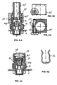
- Fig. 1 is a valve neck 10 for a valve on a gas-carrying housing in partial section 2 shown.
- the valve connector 10 carries a pressure gauge 44 on the connecting part 40 for small pressures.
- the valve stub 10 is welded to one inside the housing 2 Nut 4 screwed in and sealed with an O-ring 12.
- a key hexagon 8 for attacking a wrench.
- In the valve socket there is one in the closing direction with a conical spring 160 Locking insert 140.
- the conical spring 160 is supported against a snap ring 170 and holds the locking insert under tension and in the closed position.
- connection parts 40 are introduced.
- the connector 40 carries a manometer 44.
- Connection parts can have different installation lengths L.
- a cap 50 is used to secure the position of the connecting part 40, 42.
- the cap has two grooves 58 on the outside, which are parallel to one another.
- the grooves 58 are in the correct position assigned to the annular groove 24 in the valve socket, so that a securing element 52 (see FIG. 4B) reach through the grooves 58 of the cap 50 and into the annular groove 24 can intervene, whereby the position of the connecting part is fixed.
- a cylinder 42 is formed to match the bore 22.
- two ring grooves 24 are formed, in each of which an O-ring 40.1 is inserted is.
- the formation of the groove dimension and the O-ring cross-sections are chosen so that the connector sits gas-tight. Furthermore, by inserting the O-rings reached a certain stiffness of the connecting part 40 in the valve socket. With the increased Friction of the O-rings can determine the position of the connector become. Unintentional turns can be avoided.
- the spring-loaded closing insert 140 sits in the valve socket.
- the closing insert closes the valve with the force of the conical spring 160 so that no gas can escape.
- the valve can be attached or screwed on the corresponding connection parts Open 40, in each of which an actuating element 41 is formed for the closing insert is.
- the actuating element is the gas chamber side Area of the cylinder 42.
- the circumferential groove 24 and its extensions are enlarged in detail (25.25 ").
- Position securing means are used that differ in their diameter can.
- a first position securing means can be suitable for the depth of the rectangular groove 24 and a second position securing device can be selected to suit the extensions. Due to the circumferential formation of the groove 24 attached connection or position securing means be rotatably secured in any direction.
- FIGS. 4B and 5 show two different securing elements (52, 54).
- 4B shows a spring clip 52, the thickness of which is adapted to the width of the groove depth 24 is.
- 5A to 5C a cap 50 ', which engages over a connecting part, with shown a locking pin 54, the larger diameter of the conical extension 25 (in Fig. 2A) is adapted.
- the cylindrical locking pin 54 has approximately in the middle waist-shaped reduction 54 'of its diameter.
- the locking pin 54 is with the spring 55 held in a basic position in which its diameter in the conical extension of the Valve socket engages. If the locking pin 54 is pressed in against the force of the spring 55, then the waist-shaped reduction 54 'reaches the area of the conical extension 25 and the cap 50 'can be detached from the valve socket.
- the closing insert 140 closes the force of the conical spring 160 Valve socket gas-tight.
- the locking insert 140 is against the Force of the conical spring 160 opened. 1
- the cylinder bolt 42 of the connecting part 40 extended to an actuator (reference numeral 41), which in the installed position of the The closing insert is pushed in and the valve is opened. Gas can flow in or out.
- FIG. 4A shows a blind plug 48 which does not come into contact with the closing insert 140 comes.
- the blind plug has no actuating element for the closing insert. With the The valve is not opened when the blind plug is attached.
- the locking insert 140 (see FIG. 3) is of cylindrical symmetry and is vertical a circumferential ring 141 to its axis in the middle.
- the ring is on the valve outlet side designed as a circumferential, burr-free sealing surface for supporting an O-ring 150.
- Gas chamber side there is a cylindrical shaft 142.
- the conical spring 160 encompasses the shaft 142, is supported on the circumferential ring 141 on the gas chamber side and centers the locking insert in the open position.
- the shaft 142 is hollow on the inside (145), as a result of which Focus shifted favorably with respect to the surface of the cone spring. Ventilauslass document there is a flow-optimized training at the closing insert. 3 is therefore, a special feature is a groove 144, which serves as a flow channel.
- the Locking insert can be made as a plastic injection molded part.
- the closing insert 140 is on the gas outlet side with cross-shaped webs 143, 143 ' Mistake. Depending on the application, the webs act on the actuating elements (41) the different connectors together.
- FIG. 5A shows a position of the connection part 40 ′′ designed as a hose connection.
- the connecting part is still outside its end position, the locking insert 140 is not activated.
- the valve is still closed.
- the locking pin 54 lies on the shaft of the valve neck above the groove 24, that is outside the locking position.
- the Hose connection 40 is sealed with an O-ring 40.1 '.
- At the lower end of the Hose connection 40 is a nose 41 a with a certain length as an actuating element formed, which cooperates with the locking insert 140 (webs 143 ', 143 "). In the lowest position (locking position) of the hose connection 40 "in the valve socket the nose 41a moves the locking insert fully into the open position.
Landscapes
- Engineering & Computer Science (AREA)
- General Engineering & Computer Science (AREA)
- Mechanical Engineering (AREA)
- Valve Housings (AREA)
- Filling Or Discharging Of Gas Storage Vessels (AREA)
Description
- 2
- Gehäusewand
- 4
- Mutter mit Innengewinde
- 8
- Schlüsselsechskant
- 10
- Ventilstutzen
- 12
- O-Ring
- 140
- Schliesseinsatz
- 141
- Auflagefläche für O-Ring (Dichtfläche)
- 142
- Zylindrischer Schaft am Schliesseinsatz
- 143
- Ausformung
- 144
- Nut als Strömungskanal
- 150
- O-Ring
- 160
- Kegelfeder
- 170
- Sprengring
- 20
- Zylinderfläche außen
- 22
- Zylinderfläche innen
- 24
- Ringnut
- 25
- konische Erweiterung der Ringnut 24
- 40 40"
- Anschlussteile (Schlauchanschluss)
- 40.1
- zwei O-Ringe - (erzeugen Schwergängigkeit)
- 40.2
- O-Ring
- 41
- Betätigungselement
- 41a
- Nase
- 42
- Zylinderbolzen
- 44
- Manometer
- L
- Aufbaulänge eines Anschlussteils
- 48
- Blindstopfen
- 50, 50'
- Befestigungselement (Überwurfkappe)
- 52
- Sicherungsfeder
- 54
- Sperrbolzen
- 55
- Feder
- 58
- Nut passend zu Ringnut 24
Claims (6)
- Ventil mit Kupplungselementen für Anschlussteile, wobei das Ventil aus einem zylindrisch ausgebildeten Ventilstutzen (10) und einem in dem Ventilstutzen (10) angeordneten Schließeinsatz (140) besteht, und der Ventilstutzen (10) an einem gasführenden Gehäuse (2) anschraubbar ist,
wobei der Schließeinsatz (140) von einer Kegelfeder (160) beaufschlagt und in Schließstellung gehalten wird und von einem Anschlussteil (40,40") in Durchlassstellung bewegbar ist; wobei an dem Ventilstutzen (10) eine zylindrische Bohrung (22) für die Aufnahme eines Anschlussteils (40,40") und ein Außenzylinder (20) zum Aufstecken einer hohlzylindrischen ein Anschlussteil (40,40") haltenden Überwurfkappe (50) ausgebildet sind,
dadurch gekennzeichnet, dass am Ventilstutzen (10) eine rechteckige Umfangsnut (24) für das Eingreifen eines Lagesicherungsmittels (52,54) für das Anschlussteil (40,40") vorhanden ist, welches die Mantelfläche der Überwurfkappe (50) durchgreift,
so dass die Umfangsnut (24) zur Aufnahme unterschiedlich dicker Lagesicherungsmittel (52, 54) mit einem sich nach außen erweiternden Profil (25,25") ausgestattet ist. - Ventil nach Anspruch 1, dadurch gekennzeichnet, dass die Tiefe der Umfangsnut (24) rechteckig ist, und nach außen eine konischen Aufweitung (25) aufweist.
- Ventil nach Anspruch 1, dadurch gekennzeichnet, dass die Tiefe der Umfangsnut (24) rechteckig ist, und die Umfangsnut (24) nach außen rechteckig erweitert (25") ist.
- Ventil nach einem der vorhergehenden Ansprüche, dadurch gekennzeichnet, dass das Lagesicherungsmittel (52) als Spannfeder (52) ausbildet ist.
- Ventil nach einem der Ansprüche 1 bis 3, dadurch gekennzeichnet, dass das Lagesicherungsmittel (54) als mit einer Feder (55) beaufschlagter Sperrbolzen (54) mit zylindrischem Schaft ausbildet ist, wobei der Durchmesser des Sperrbolzens der außen liegenden Aufweitung (25, 25") der Ringnut (24) entspricht.
- Verwendung eines Ventils mit Kupplungselementen nach einem der vorhergehenden Ansprüche für das Gehäuse einer SF6-Mittelspannungsschaltanlage.
Applications Claiming Priority (2)
| Application Number | Priority Date | Filing Date | Title |
|---|---|---|---|
| DE10008529 | 2000-02-24 | ||
| DE10008529 | 2000-02-25 |
Publications (3)
| Publication Number | Publication Date |
|---|---|
| EP1128102A2 EP1128102A2 (de) | 2001-08-29 |
| EP1128102A3 EP1128102A3 (de) | 2002-10-02 |
| EP1128102B1 true EP1128102B1 (de) | 2004-11-10 |
Family
ID=7632159
Family Applications (1)
| Application Number | Title | Priority Date | Filing Date |
|---|---|---|---|
| EP01103922A Expired - Lifetime EP1128102B1 (de) | 2000-02-24 | 2001-02-17 | Ventil mit Kupplungselementen |
Country Status (4)
| Country | Link |
|---|---|
| EP (1) | EP1128102B1 (de) |
| CN (1) | CN1193182C (de) |
| DE (2) | DE50104448D1 (de) |
| ES (1) | ES2240254T3 (de) |
Families Citing this family (7)
| Publication number | Priority date | Publication date | Assignee | Title |
|---|---|---|---|---|
| AU2005233846B2 (en) * | 2004-04-15 | 2008-09-11 | Daikin Industries, Ltd. | Joint |
| ITMI20060037U1 (it) * | 2006-02-01 | 2007-08-02 | Caleffi Spa | Valvola perfezionata di sicurezza per caldaie murali |
| CN107504246A (zh) * | 2017-08-01 | 2017-12-22 | 国家电网公司 | 一种高压充气过渡阀及其配套的储气罐 |
| CN113124192A (zh) * | 2019-12-30 | 2021-07-16 | 浙江三花智能控制股份有限公司 | 一种电动阀及热水器 |
| CN113124193B (zh) * | 2019-12-30 | 2023-08-11 | 浙江三花智能控制股份有限公司 | 一种电动阀、热水器及电动阀的控制方法 |
| CN113124191A (zh) * | 2019-12-30 | 2021-07-16 | 浙江三花智能控制股份有限公司 | 一种电动阀、热水器及电动阀的手动控制方法 |
| CN112546762B (zh) * | 2020-12-29 | 2022-06-14 | 江苏安瑞森电子材料有限公司 | 一种氧气提纯设备及其工艺 |
Family Cites Families (9)
| Publication number | Priority date | Publication date | Assignee | Title |
|---|---|---|---|---|
| BE363976A (de) * | ||||
| GB732186A (en) * | 1952-06-06 | 1955-06-22 | Scandinavian Agencies Corp Ltd | Improvements relating to conduit couplings |
| FR1286061A (fr) * | 1961-01-20 | 1962-03-02 | Pingeot & Cie Ets | Robinet à clapet de sécurité pour bouteille de butane ou d'autre gaz comprimé |
| GB1117169A (en) * | 1966-02-23 | 1968-06-19 | Pirelli | Improvements in or relating to non-return valves for use with pressurized fluid-filled containers |
| US4009896A (en) * | 1976-05-10 | 1977-03-01 | General Motors Corporation | Quick connect coupling |
| WO1980001311A1 (en) | 1978-12-20 | 1980-06-26 | Abnox Ag | Pipe coupling |
| GB2067697A (en) * | 1980-01-02 | 1981-07-30 | Skol Brouwerijen Nv | Releasable pipe coupling |
| NL183475C (nl) | 1980-09-25 | Festo Maschf Stoll G | Aansluitverbindingsstuk voor het aansluiten van een uit elastisch materiaal bestaande leiding. | |
| DE4210773C2 (de) | 1992-04-01 | 1995-11-02 | Felten & Guilleaume Energie | Metallgekapselte, druckgasisolierte SF¶6¶-Schaltanlage mit einer Sammelschienenanordnung |
-
2001
- 2001-02-17 DE DE50104448T patent/DE50104448D1/de not_active Expired - Lifetime
- 2001-02-17 ES ES01103922T patent/ES2240254T3/es not_active Expired - Lifetime
- 2001-02-17 EP EP01103922A patent/EP1128102B1/de not_active Expired - Lifetime
- 2001-02-21 DE DE20103054U patent/DE20103054U1/de not_active Expired - Lifetime
- 2001-02-23 CN CNB011049073A patent/CN1193182C/zh not_active Expired - Fee Related
Also Published As
| Publication number | Publication date |
|---|---|
| CN1339663A (zh) | 2002-03-13 |
| DE50104448D1 (de) | 2004-12-16 |
| EP1128102A3 (de) | 2002-10-02 |
| CN1193182C (zh) | 2005-03-16 |
| DE20103054U1 (de) | 2001-06-28 |
| ES2240254T3 (es) | 2005-10-16 |
| EP1128102A2 (de) | 2001-08-29 |
Similar Documents
| Publication | Publication Date | Title |
|---|---|---|
| DE69324817T2 (de) | Schnellkupplung für hohe drücke | |
| EP2176554B1 (de) | Sicherheitseinrichtung für druckmedien einschliessende behälter | |
| DE3928014A1 (de) | Hydraulische unterwasserkupplung mit schwalbenschwanzdichtung | |
| DE2011409B2 (de) | Ventilschnellkupplung für zwei gas- oder flüssigkeitsführende Leitungen | |
| EP0803676A1 (de) | Schnellkupplung für die Verbindung von Schlauch- und Rohrleitungen | |
| DE3604194A1 (de) | Stopfen fuer waermetauscherrohre oder -leitungen | |
| EP1540234B1 (de) | Adapter-zwischenring für ein einschraubteil eines fluid-stecksystems | |
| DE112020002258T5 (de) | Kopf für Druckgasbehälter | |
| DE20116899U1 (de) | Strömungswächter | |
| EP0863337A2 (de) | Ventilarmatur für einen Druckbehälter | |
| EP1128102A2 (de) | Ventil an einem gasführenden Gehäuse | |
| DE19533917C2 (de) | Hydraulische Unterwasserkupplung mit axialer Vorlast | |
| DE4213732A1 (de) | Verschlußstück zum Abschließen von Druckmittel führenden Bohrungen | |
| DE4340783A1 (de) | Kupplungsnippel | |
| EP1745231B1 (de) | Kupplung für eine druckgasflasche | |
| DE102012018731A1 (de) | Sicherheitsabsperrvorrichtung und Verfahren zu seiner Herstellung | |
| DE202007018625U1 (de) | Schneidbrenner mit einem Brennerkopf, der eine auswechselbare Schneiddüse aufnimmt | |
| DE3825575C2 (de) | ||
| EP0879377A1 (de) | Lösbare rohrverbindung für kunststoffrohre | |
| DE4007279C2 (de) | Anschlußvorrichtung für Einstutzen-Gaszähler | |
| DE10150561C1 (de) | Entlüftungskupplung mit Kraftkompensation an der Betätigungshülse | |
| WO2011057702A1 (de) | Ventil mit demontageschutz sowie montagehilfe | |
| DE102007023566B4 (de) | Pumpenanschluß für Presta-Ventil | |
| EP2023027A2 (de) | Schlauchanschluss | |
| WO2008125188A1 (de) | Kurzbauender stecker für fluidkupplungen |
Legal Events
| Date | Code | Title | Description |
|---|---|---|---|
| PUAI | Public reference made under article 153(3) epc to a published international application that has entered the european phase |
Free format text: ORIGINAL CODE: 0009012 |
|
| AK | Designated contracting states |
Kind code of ref document: A2 Designated state(s): AT BE CH CY DE DK ES FI FR GB GR IE IT LI LU MC NL PT SE TR |
|
| AX | Request for extension of the european patent |
Free format text: AL;LT;LV;MK;RO;SI |
|
| PUAL | Search report despatched |
Free format text: ORIGINAL CODE: 0009013 |
|
| AK | Designated contracting states |
Kind code of ref document: A3 Designated state(s): AT BE CH CY DE DK ES FI FR GB GR IE IT LI LU MC NL PT SE TR |
|
| AX | Request for extension of the european patent |
Free format text: AL;LT;LV;MK;RO;SI |
|
| 17P | Request for examination filed |
Effective date: 20020905 |
|
| AKX | Designation fees paid |
Designated state(s): AT BE CH CY DE DK ES FI FR GB GR IE IT LI LU MC NL PT SE TR |
|
| 17Q | First examination report despatched |
Effective date: 20030821 |
|
| GRAP | Despatch of communication of intention to grant a patent |
Free format text: ORIGINAL CODE: EPIDOSNIGR1 |
|
| RTI1 | Title (correction) |
Free format text: VALVE WITH COUPLING ELEMENTS |
|
| GRAS | Grant fee paid |
Free format text: ORIGINAL CODE: EPIDOSNIGR3 |
|
| RAP1 | Party data changed (applicant data changed or rights of an application transferred) |
Owner name: FELTEN & GUILLEAUME AG |
|
| RBV | Designated contracting states (corrected) |
Designated state(s): BE CH DE ES FI FR GB IT LI NL |
|
| GRAA | (expected) grant |
Free format text: ORIGINAL CODE: 0009210 |
|
| AK | Designated contracting states |
Kind code of ref document: B1 Designated state(s): BE CH DE ES FI FR GB IT LI NL |
|
| REG | Reference to a national code |
Ref country code: GB Ref legal event code: FG4D Free format text: NOT ENGLISH |
|
| REG | Reference to a national code |
Ref country code: CH Ref legal event code: EP |
|
| RAP2 | Party data changed (patent owner data changed or rights of a patent transferred) |
Owner name: MOELLER ANLAGENTECHNIK GMBH |
|
| REG | Reference to a national code |
Ref country code: IE Ref legal event code: FG4D Free format text: GERMAN |
|
| REF | Corresponds to: |
Ref document number: 50104448 Country of ref document: DE Date of ref document: 20041216 Kind code of ref document: P |
|
| NLT2 | Nl: modifications (of names), taken from the european patent patent bulletin |
Owner name: MOELLER ANLAGENTECHNIK GMBH |
|
| REG | Reference to a national code |
Ref country code: CH Ref legal event code: PFA Owner name: ORMAZABAL ANLAGENTECHNIK GMBH Free format text: MOELLER ANLAGENTECHNIK GMBH#HEIN-MOELLER-STR. 7-11#53115 BONN (DE) -TRANSFER TO- ORMAZABAL ANLAGENTECHNIK GMBH#AM NEUERHOF 31#47804 KREFELD (DE) |
|
| PGFP | Annual fee paid to national office [announced via postgrant information from national office to epo] |
Ref country code: GB Payment date: 20050208 Year of fee payment: 5 |
|
| PGFP | Annual fee paid to national office [announced via postgrant information from national office to epo] |
Ref country code: FI Payment date: 20050210 Year of fee payment: 5 Ref country code: FR Payment date: 20050210 Year of fee payment: 5 |
|
| PGFP | Annual fee paid to national office [announced via postgrant information from national office to epo] |
Ref country code: NL Payment date: 20050211 Year of fee payment: 5 |
|
| PGFP | Annual fee paid to national office [announced via postgrant information from national office to epo] |
Ref country code: CH Payment date: 20050216 Year of fee payment: 5 |
|
| REG | Reference to a national code |
Ref country code: CH Ref legal event code: NV Representative=s name: E. BLUM & CO. PATENTANWAELTE |
|
| PGFP | Annual fee paid to national office [announced via postgrant information from national office to epo] |
Ref country code: BE Payment date: 20050309 Year of fee payment: 5 |
|
| GBT | Gb: translation of ep patent filed (gb section 77(6)(a)/1977) |
Effective date: 20050228 |
|
| REG | Reference to a national code |
Ref country code: IE Ref legal event code: FD4D |
|
| REG | Reference to a national code |
Ref country code: FR Ref legal event code: CD |
|
| PLBE | No opposition filed within time limit |
Free format text: ORIGINAL CODE: 0009261 |
|
| STAA | Information on the status of an ep patent application or granted ep patent |
Free format text: STATUS: NO OPPOSITION FILED WITHIN TIME LIMIT |
|
| ET | Fr: translation filed | ||
| REG | Reference to a national code |
Ref country code: ES Ref legal event code: FG2A Ref document number: 2240254 Country of ref document: ES Kind code of ref document: T3 Ref country code: ES Ref legal event code: PC2A |
|
| 26N | No opposition filed |
Effective date: 20050811 |
|
| PG25 | Lapsed in a contracting state [announced via postgrant information from national office to epo] |
Ref country code: FI Free format text: LAPSE BECAUSE OF NON-PAYMENT OF DUE FEES Effective date: 20060217 Ref country code: GB Free format text: LAPSE BECAUSE OF NON-PAYMENT OF DUE FEES Effective date: 20060217 |
|
| PG25 | Lapsed in a contracting state [announced via postgrant information from national office to epo] |
Ref country code: LI Free format text: LAPSE BECAUSE OF NON-PAYMENT OF DUE FEES Effective date: 20060228 Ref country code: CH Free format text: LAPSE BECAUSE OF NON-PAYMENT OF DUE FEES Effective date: 20060228 Ref country code: BE Free format text: LAPSE BECAUSE OF NON-PAYMENT OF DUE FEES Effective date: 20060228 |
|
| PGFP | Annual fee paid to national office [announced via postgrant information from national office to epo] |
Ref country code: IT Payment date: 20060228 Year of fee payment: 6 |
|
| PG25 | Lapsed in a contracting state [announced via postgrant information from national office to epo] |
Ref country code: NL Free format text: LAPSE BECAUSE OF NON-PAYMENT OF DUE FEES Effective date: 20060901 |
|
| REG | Reference to a national code |
Ref country code: CH Ref legal event code: PL |
|
| GBPC | Gb: european patent ceased through non-payment of renewal fee |
Effective date: 20060217 |
|
| NLV4 | Nl: lapsed or anulled due to non-payment of the annual fee |
Effective date: 20060901 |
|
| REG | Reference to a national code |
Ref country code: FR Ref legal event code: ST Effective date: 20061031 |
|
| BERE | Be: lapsed |
Owner name: *MOELLER ANLAGENTECHNIK G.M.B.H. Effective date: 20060228 |
|
| PG25 | Lapsed in a contracting state [announced via postgrant information from national office to epo] |
Ref country code: FR Free format text: LAPSE BECAUSE OF NON-PAYMENT OF DUE FEES Effective date: 20060228 |
|
| PG25 | Lapsed in a contracting state [announced via postgrant information from national office to epo] |
Ref country code: IT Free format text: LAPSE BECAUSE OF NON-PAYMENT OF DUE FEES Effective date: 20070217 |
|
| PGFP | Annual fee paid to national office [announced via postgrant information from national office to epo] |
Ref country code: ES Payment date: 20100223 Year of fee payment: 10 |
|
| PGFP | Annual fee paid to national office [announced via postgrant information from national office to epo] |
Ref country code: DE Payment date: 20100219 Year of fee payment: 10 |
|
| REG | Reference to a national code |
Ref country code: DE Ref legal event code: R119 Ref document number: 50104448 Country of ref document: DE Effective date: 20110901 |
|
| REG | Reference to a national code |
Ref country code: ES Ref legal event code: FD2A Effective date: 20120411 |
|
| PG25 | Lapsed in a contracting state [announced via postgrant information from national office to epo] |
Ref country code: ES Free format text: LAPSE BECAUSE OF NON-PAYMENT OF DUE FEES Effective date: 20110218 |
|
| PG25 | Lapsed in a contracting state [announced via postgrant information from national office to epo] |
Ref country code: DE Free format text: LAPSE BECAUSE OF NON-PAYMENT OF DUE FEES Effective date: 20110901 |