EP1126256A2 - Fabry-Perot-Filter, wellenlängenselektiver Infrarotdetektor und einen solchen Filter/Detektor verwendender Infrarot-Gasanalysator - Google Patents
Fabry-Perot-Filter, wellenlängenselektiver Infrarotdetektor und einen solchen Filter/Detektor verwendender Infrarot-Gasanalysator Download PDFInfo
- Publication number
- EP1126256A2 EP1126256A2 EP01103340A EP01103340A EP1126256A2 EP 1126256 A2 EP1126256 A2 EP 1126256A2 EP 01103340 A EP01103340 A EP 01103340A EP 01103340 A EP01103340 A EP 01103340A EP 1126256 A2 EP1126256 A2 EP 1126256A2
- Authority
- EP
- European Patent Office
- Prior art keywords
- wavelength
- selective
- fabry
- filter
- infrared
- Prior art date
- Legal status (The legal status is an assumption and is not a legal conclusion. Google has not performed a legal analysis and makes no representation as to the accuracy of the status listed.)
- Withdrawn
Links
Images


Classifications
-
- G—PHYSICS
- G01—MEASURING; TESTING
- G01J—MEASUREMENT OF INTENSITY, VELOCITY, SPECTRAL CONTENT, POLARISATION, PHASE OR PULSE CHARACTERISTICS OF INFRARED, VISIBLE OR ULTRAVIOLET LIGHT; COLORIMETRY; RADIATION PYROMETRY
- G01J3/00—Spectrometry; Spectrophotometry; Monochromators; Measuring colours
- G01J3/12—Generating the spectrum; Monochromators
- G01J3/26—Generating the spectrum; Monochromators using multiple reflection, e.g. Fabry-Perot interferometer, variable interference filters
-
- G—PHYSICS
- G01—MEASURING; TESTING
- G01N—INVESTIGATING OR ANALYSING MATERIALS BY DETERMINING THEIR CHEMICAL OR PHYSICAL PROPERTIES
- G01N21/00—Investigating or analysing materials by the use of optical means, i.e. using sub-millimetre waves, infrared, visible or ultraviolet light
- G01N21/17—Systems in which incident light is modified in accordance with the properties of the material investigated
- G01N21/25—Colour; Spectral properties, i.e. comparison of effect of material on the light at two or more different wavelengths or wavelength bands
- G01N21/31—Investigating relative effect of material at wavelengths characteristic of specific elements or molecules, e.g. atomic absorption spectrometry
- G01N21/35—Investigating relative effect of material at wavelengths characteristic of specific elements or molecules, e.g. atomic absorption spectrometry using infrared light
- G01N21/3504—Investigating relative effect of material at wavelengths characteristic of specific elements or molecules, e.g. atomic absorption spectrometry using infrared light for analysing gases, e.g. multi-gas analysis
Definitions
- the present invention relates to a Fabry-Perot filter used as a wavelength-selective filter for admitting rays of light (e.g., infrared radiation) in a wavelength-selective way; a wavelength-selective infrared detector configured by integrating the Fabry-Perot filter with an infrared detector; and a non-dispersive infrared gas analyzer for measuring the concentration of a gas or gases in the atmosphere, for example, by detecting infrared radiation that transmits through the Fabry-Perot filter.
- rays of light e.g., infrared radiation
- a wavelength-selective infrared detector configured by integrating the Fabry-Perot filter with an infrared detector
- a non-dispersive infrared gas analyzer for measuring the concentration of a gas or gases in the atmosphere, for example, by detecting infrared radiation that transmits through the Fabry-Perot filter.
- a non-dispersive infrared gas analyzer (hereinafter abbreviated as an NDIR gas analyzer) is used, wherein the analyzer detects the amount of infrared absorption to measure the concentration of a gas, taking advantage of the fact that the wavelength bands of infrared radiation to be absorbed varies depending on the type of gas.
- FIGS. 1 to 5 are schematic views showing configuration examples of prior art NDIR gas analyzers.
- the gas being measured is assumed to be carbon dioxide whose peak wavelength of infrared absorption is approximately 4.25 ⁇ m.
- FIG. 1 schematically shows the configuration of a single-ray, onewavelength NDIR gas analyzer comprising a sample cell 110 whereinto a gas is supplied, a light source 111, a filter 112, and an infrared detector 113.
- the filter 112 is tuned to the absorption bands of carbon dioxide shown in FIG. 6 to select and pass a band of infrared radiation having wavelengths in the vicinity of 4.25 ⁇ m.
- the infrared detector 113 determines the concentration of the gas being measured by detecting infrared radiation passing through the filter 112.
- FIG. 2 schematically shows the configuration of a single-ray twowavelength comparative NDIR gas analyzer.
- the analyzer selects two wavelength bands using the filter 112 tuned to the absorption band of carbon dioxide and a filter 114 for passing an infrared radiation band of wavelengths in the vicinity of approximately 3.9 ⁇ m as reference light.
- the bands of infrared radiation thus selected are detected respectively with infrared detectors 113 and 115.
- FIG. 3 schematically shows the configuration of another single-ray twowavelength comparative NDIR gas analyzer.
- the analyzer selects two wavelength bands using the filter 112 formed on a disc 116 and tuned to the absorption band of carbon dioxide and the filter 114 for reference light.
- the bands of infrared radiation selected with the filters as the disc 116 is rotated are then detected with the infrared detector 113.
- FIG. 4 schematically shows the configuration of a single-ray twowavelength Fabry-Perot NDIR gas analyzer.
- a gap between two mutually parallel mirrors comprising a Fabry-Perot filter 117 is made variable so that two bands are selected, one being a band tuned to the absorption band of the gas being measured and the other being the band of reference light.
- the bands of infrared radiation thus selected are respectively detected with the infrared detector 113.
- the Fabry-Perot filter is, as shown in FIG. 8, an optical filter using a device (Fabry-Perot plates) wherein a pair of high-reflectance mirrors 120 and 121 are placed in parallel and opposite to each other and a gap is formed therebetween.
- the Fabry-Perot filter is designed so that the wavelength bands of the transmitted light passing through the device can be varied by making the gap width d variable.
- a variable-wavelength Fabry-Perot filter there has been a filter having a fixed mirror, a movable mirror arranged opposite to the fixed mirror with a gap formed therebetween, a fixed electrode formed on the fixed mirror, and a movable electrode formed on the movable mirror, wherein the gap is made variable by applying a voltage across the fixed and movable electrodes and thereby displacing the movable mirror with respect to the fixed mirror.
- variable-wavelength Fabry-Perot filter that is used as a wavelength-selective filter for non-dispersive infrared carbon dioxide (CO 2 ) sensors and selectively passes the wavelength band of carbon dioxide absorption (approximately 4.25 ⁇ m) and the wavelength band of reference-purpose light (approximately 3.9 ⁇ m).
- FIG. 5 schematically shows the configuration of a double-ray, onewavelength NDIR gas analyzer, wherein two light sources 111 and 118 are arranged so that the optical paths thereof differ from each other within the sample cell 110.
- a change in the output signal with time due to, for example, contamination in the sample cell 110 is corrected according to the ratio between two output signals of the infrared detector 113 provided by a band of infrared radiation that passes through the filter 112 tuned to the absorption band of the gas being measured. The concentration of the gas being measured is then determined.
- a primary purpose of the invention is, therefore, to provide an infrared gas analyzer capable of simultaneously determining the concentrations of at least two constituents of a gas being measured, by realizing a Fabry-Perot filter for selectively passing at least three wavelength bands of infrared radiation, including a band of reference light.
- the Fabry-Perot filter, wavelength-selective infrared detector and infrared gas analyzer according to the present invention which is directed to solving the above-noted problem, are defined respectively as:
- FIG. 1 is a schematic view showing the configuration of a prior art NDIR gas analyzer.
- FIG. 2 is a schematic view showing the configuration of another prior art NDIR gas analyzer.
- FIG. 3 is a schematic view showing the configuration of yet another prior art NDIR gas analyzer.
- FIG. 4 is a schematic view showing the configuration of yet another prior art NDIR gas analyzer.
- FIG. 5 is a schematic view showing the configuration of yet another prior art NDIR gas analyzer.
- FIG. 6 is a graph showing the infrared transmission and absorption bands of a filter.
- FIG. 7 is a graph showing the infrared transmission and absorption bands of another filter.
- FIG. 8 is a schematic view explaining Fabry-Perot plates.
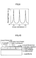
- FIG. 9 is a graph showing the way light transmits through a Fabry-Perot filter.
- FIG. 10 is a cross-sectional view schematically showing the configuration of a first embodiment of the Fabry-Perot filter according to the present invention.
- FIG. 11 is a graph showing the infrared absorption band of carbon dioxide.
- FIG. 12 is a graph showing the absorption band of water vapor.
- FIG. 13 is a schematic view explaining the behavior of the first embodiment of the Fabry-Perot filter according to the present invention.
- FIG. 14 is a graph showing the transmission and gas absorption bands of the Fabry-Perot filter.
- FIG. 15 is a schematic view showing the configuration of an infrared gas analyzer using the Fabry-Perot filter shown in FIG. 13.
- FIG. 16 is a cross-sectional view schematically showing the configuration of a first embodiment of the wavelength-selective infrared detector according to the present invention.
- FIG. 17 is a cross-sectional view schematically showing the configuration of a second embodiment of the wavelength-selective infrared detector according to the present invention.
- FIG. 18 is a cross-sectional view schematically showing the configuration of a third embodiment of the wavelength-selective infrared detector according to the present invention.
- FIG. 19 is a schematic view showing the configuration of an infrared gas analyzer using the second and third embodiments of the wavelengthselective infrared detector according to the present invention.
- FIG. 20 is a schematic view explaining the Fabry-Perot filter.
- FIG. 21 is a cross-sectional view schematically explaining the way a gap is formed in the Fabry-Perot filter.
- FIG. 22 is a cross-sectional view schematically showing the configuration of the Fabry-Perot filter according to the present invention.
- FIG. 23 is a graph showing the transmission characteristics of Fabry-Perot filters, one of which using a single layer and the other using three layers for the movable mirrors thereof.
- FIG. 24 is a schematic view explaining an example of the Fabry-Perot filter using a three-layer movable mirror.
- FIG. 25 is a schematic view explaining an example of the Fabry-Perot filter using a single-layer movable mirror.
- FIG. 26 is a schematic view showing an example of a multilayer movable mirror.
- FIG. 27 is a cross-sectional view schematically showing the configuration of a second embodiment of the Fabry-Perot filter according to the present invention.
- FIG. 28 is a cross-sectional view schematically showing the configuration of a third embodiment of the Fabry-Perot filter according to the present invention.
- FIG. 29 is a cross-sectional view schematically showing the configuration of a fourth embodiment of the Fabry-Perot filter according to the present invention.
- FIG. 30 is a cross-sectional view schematically showing the configuration of a fifth embodiment of the Fabry-Perot filter according to the present invention.
- FIG. 31 is a cross-sectional view schematically showing the configuration of a sixth embodiment of the Fabry-Perot filter according to the present invention.
- FIG. 10 is a cross-sectional view schematically showing the configuration of a first embodiment of the Fabry-Perot filter according to the present invention (claims 1 to 3).
- the gas being measured is a gas containing two components, one of which is carbon dioxide whose peak wavelength of infrared absorption is approximately 4.25 ⁇ m, as shown in FIG. 11, and the other is water vapor whose peak wavelength of infrared absorption is approximately 2.7 ⁇ m, as shown in FIG. 12.
- a fixed mirror 3 is formed on a silicon substrate 1 via an oxide layer 2 and a movable mirror 4 is formed on an oxide layer 5 deposited on the fixed mirror 3 and arranged opposite to the fixed mirror 3.
- a gap h equivalent to the thickness of the oxide layer 5 is formed between the fixed mirror 3 and movable mirror 4, by etching the oxide layer 5 through etching holes 6 formed on the movable mirror 4.
- the movable mirror 4 can be displaced toward the fixed mirror 3 by applying external force.
- the fixed mirror 3 and movable mirror 4 are made of, for example, polysilicon.
- a fixed electrode 7 is formed on the fixed mirror 3 by doping the surface thereof with a high-concentration impurity or impurities.
- a movable electrode 8 is formed on the movable mirror 4 by doping the surface thereof with a high-concentration impurity or impurities.
- An electrode pad 9 is formed on the fixed electrode 7 in contact therewith to enable the electrode to be electrified externally.
- an electrode pad 10 is formed on the movable electrode 8 in contact therewith to enable the electrode to be electrified externally.
- FIGS. 13a, 13b and 13c are schematic views explaining the behavior of the Fabry-Perot filter shown in FIG. 10.
- the width of the gap h i.e., the thickness of an isolation layer of approximately 3100 nm
- the width of the gap h i.e., the thickness of an isolation layer of approximately 3100 nm
- the width of the gap h i.e., the thickness of an isolation layer of approximately 3100 nm
- the object to be measured can be switched to water vapor by adjusting the potential difference, so that the gap h is approximately 2590 nm, as shown in FIG. 13b.
- the object can further be switched to carbon dioxide by adjusting the potential difference so that the gap h is approximately 2270 nm, as shown in FIG. 13c.
- the gap h is made variable in three steps. Consequently, it is possible to realize a Fabry-Perot filter for selectively passing at least three wavelength bands of infrared radiation, including a wavelength band of reference light.
- an infrared gas analyzer comprising a light source for emitting infrared radiation to the gas being measured, a wavelength-selective filter for passing the infrared radiation from the light source in a wavelength-selective way, and an infrared detector for detecting infrared radiation passing through the wavelength-selective filter, in order to determine the concentration of the gas being measured according to the output of the infrared detector. Then, it is possible to simultaneously measure the concentrations of two constituents of the gas being measured, without having to increase the number of wavelength-selective filters. Consequently, it is possible to reduce both the size and cost of the infrared gas analyzer.
- the Fabry-Perot filter presents a plurality of transmission peaks in a plurality of wavelength bands, as shown in FIG. 14.
- the object being measured is carbon dioxide for which the gap h is set to 2270 nm
- transmission peaks exist in the vicinity of 2400 nm and 4250 nm
- the object is water vapor for which the gap is set to 2590 nm
- transmission peaks exist in the vicinity of 2700 nm and 4700 nm
- transmission peaks exist in the vicinity of 2200 nm and 3100 nm.
- a wide bandpass filter 12 for passing, for example, only the wavelength band of 2600 to 4500 nm and rejecting all other bands can be located before an infrared detector 14 in the optical path, so that only one peak is selected for each width of the gap. That is, as shown in FIG. 14, only a band of wavelengths in the vicinity of 4250 nm is selected for carbon dioxide for which the gap h is set to 2270 nm; only a band of wavelengths in the vicinity of 2700 nm is selected for water vapor for which the gap is set to 2590 nm; and only a band of wavelengths in the vicinity of 3100 nm is selected for reference light for which the gap is set to 3100 nm.
- the Fabry-Perot filter permits a plurality of gases to be measured with regard to the amount of absorption.
- the wide bandpass filter 12 is located between a light source 11 and a Fabry-Perot filter 13 in the optical path.
- the wide bandpass filter 12 may be located between the Fabry-Perot filter 13 and the infrared detector 14 in the optical path.
- the optical axes of the Fabry-Perot filter 13 and infrared detector 14 must be positioned so as to be in line with each other.
- the Fabry-Perot filter 13 and infrared detector 14 are two separate elements and are difficult to align precisely. Accordingly, instrument-to-instrument measurement errors may occur depending on the variance of alignment accuracy.
- the infrared detector 14 In order to increase the sensitivity of the infrared detector 14 and prevent the characteristics thereof from changing with time, the infrared detector 14 must be encapsulated in a package and the package must be vacuum-sealed or sealed with an inert gas inside.
- the Fabry-Perot filter is integrated with the infrared detector to form a wavelength-selective infrared detector.
- Embodiments of the wavelength-selective infrared detector according to the present invention are explained in detail hereafter.
- FIG. 16 is a cross-sectional view schematically showing the configuration of a first embodiment of the wavelength-selective infrared detector according to the present invention. Note that components identical to those of FIG. 10 are referenced alike.
- an infrared detector 21 is integrated with a wavelength-selective (Fabry-Perot) filter 22 to form a wavelength-selective infrared detector.
- Fabry-Perot wavelength-selective
- the infrared detector 21 is, for example, a bolometer wherein a sealed cavity 23, infrared detector elements 24 formed therein, and electrodes 25a and 25b wherethrough the infrared detector 24 is electrified, are formed on a silicon substrate 26.
- the infrared detector elements 24 are formed by spirally etching an conductive infrared detector layer 29 formed between isolation layers 27 and 28 consisting of silicon oxide layers that are deposited on the substrate 26.
- the infrared detector layer 29 is made of, for example, silicon with a high impurity concentration.
- etching holes 31 are formed between the spacer layer 30 and isolation layer 28. Then, the sealed cavity 23 is formed by applying concentration-difference etching through the etching holes 31 to a portion of the substrate 26 underlying the infrared detector elements 24, whereby the elements are made afloat within the sealed cavity 23.
- a sealing layer 32 made of silicon is formed on the spacer layer 30 by means of, for example, epitaxial growth, thereby closing the etching holes 31.
- the sealed cavity 23 is filled with hydrogen that serves as a carrier gas during epitaxial growth.
- the sealed cavity 23 is then heat-treated to drive the hydrogen out of the cavity so that a vacuum is formed therein. Consequently, the infrared detector elements 24 are vacuum-sealed inside the sealed cavity 23.
- the wavelength-selective filter 22 is a Fabry-Perot filter, which is identical to the Fabry-Perot filter shown in FIG. 10 with regard to primary components and comprises a fixed mirror 3, a movable mirror 4 arranged opposite to the fixed mirror 3, a fixed electrode 7 formed on the fixed mirror 3 and a movable electrode 8 formed on the movable mirror 4.
- a gap 33 is formed between the fixed mirror 3 and movable mirror 4, wherein the movable mirror 4 can be displaced toward the fixed mirror 3.
- an isolation layer 34 made of silicon oxide is formed on the sealing layer 32 serving as a substrate.
- the fixed mirror 3 which is made of, for example, polysilicon, is then formed on the isolation layer 34.
- a high concentration of impurity is doped onto the surface of the fixed mirror 3 to form the fixed electrode 7.
- Another isolation layer 35 is formed on the fixed mirror 3, and the movable mirror 4, which is made of, for example, polysilicon, is formed on the isolation layer 35 so as to be opposite to the fixed mirror 3.
- the movable electrode 8 doped with a high concentration of impurity is formed so as to be opposite to the fixed electrode 7.
- the isolation layer 35 is etched through the etching holes so that a gap 33, whose width is equivalent to the thickness of the isolation layer 35, is formed between the fixed mirror 3 and movable mirror 4.
- the movable mirror 4 is connected through the isolation layer 35 to the fixed mirror 3, taking the form of a cantilever.
- a plurality of etching holes 6 may be formed in a circular array in the movable mirror 4 to etch the isolation layer 35, so that the movable mirror 4 takes the form of a diaphragm.
- the electrode pad 9 is formed on the fixed electrode 7 in contact therewith to enable the electrode to be electrified externally.
- the electrode pad 10 is formed on the movable electrode 8 in contact therewith to enable the electrode to be electrified externally.
- the width of the gap 33 i.e., the thickness of the isolation layer 35
- this initial state is the mode of measuring reference light.
- the object to be measured can be switched to carbon dioxide by setting the gap to approximately 2.27 ⁇ m.
- the object can further be switched to water vapor by setting the gap to approximately 2.59 ⁇ m.
- Infrared radiation emitted from a light source enters a sample cell (not shown in the figure) whereinto the gas being measured is supplied, where only a specific band of wavelengths is absorbed and projected onto the movable mirror 4. Only the wavelength component among those of the projected infrared radiation corresponding to the width of the gap 33 passes through the fixed mirror 3 and enters the infrared detector elements 24 within the sealed cavity 23 of the infrared detector 21.
- the infrared detector elements 24 determine the concentration of the gas being measured.
- FIG. 17 is a cross-sectional view schematically showing the configuration of a second embodiment of the wavelength-selective infrared detector according to the present invention. Note that components identical to those of FIG. 16 are referenced alike and excluded from the description as necessary.
- an infrared detector 21 formed on a silicon substrate 26 serving as a first substrate and a waveform-selective filter 22 formed on a silicon substrate 1 serving as a second substrate are joined together to form a waveform-selective infrared detector.
- the infrared detector 21 is, for example, a bolometer, wherein a cavity 36 serving as a sealed cavity, infrared detector elements 24 arranged in the cavity 36, and electrodes 25a and 25b for electrifying the infrared detector elements 24 are formed on the substrate 26.
- the infrared detector elements 24 are formed by spirally etching an infrared detector layer 29 formed between isolation layers 27 and 28 that are deposited on the substrate 26. Then, the cavity 36 is formed by etching a portion of the substrate 26 underlying the infrared'detector elements 24 into the shape of a groove using a concentration difference method.
- the wavelength-selective filter 22 is a Fabry-Perot filter wherein the fixed mirror 3, the movable mirror 4, the fixed electrode 7 located on the fixed mirror 3, and the movable electrode 8 located on the movable mirror 4 are formed on the substrate 1.
- Another cavity 37 is formed on the backside of the substrate 1.
- the sealed cavity 23 is formed by directly joining together the substrate 26 whereon the infrared detector 21 is formed and the substrate 1 whereon the wavelength-selective filter 22 is formed, in a vacuum or inert gas atmosphere, with the cavities 36 and 37 opposed to each other.
- the infrared detector elements 24 are made afloat within the sealed cavity 23. In this process, the sealed cavity 23 is vacuum-sealed or sealed with an inert gas inside.
- the wavelength-selective infrared detector is configured in such a manner that the wavelength-selective filter 22 of the wavelength-selective infrared detector shown in FIG. 17a is positioned upside down.
- the infrared detector 21 and wavelength-selective filter 22 are joined together through the spacer layer 38 whereon the cavity 37 is formed and the cavity 23 is vacuum-sealed or sealed with an inert gas inside.
- the electrode pad 9 is formed so that the fixed electrode 7 can be thereby electrified through an antireflection layer 39 deposited on the substrate 1, the substrate 1 and the isolation layer 2.
- the electrode pad 10 is formed so that the movable electrode 8 can be thereby electrified through the antireflection layer 39, the substrate 1, the isolation layer 2, the fixed mirror 3 and the isolation layer 35.
- Such wavelength-selective infrared detectors as described above and shown in FIGS. 16 and 17 are fabricated using a semiconductor manufacturing process that allows for precision alignment. This means it is possible to align the infrared detector 21 and wavelength-selective filter 22 with high precision, thereby reducing an instrument-to-instrument error.
- the wavelength-selective infrared detectors are designed so that the gap 33 of the Fabry-Perot filter can be varied by changing a voltage applied across the fixed electrode 7 and movable electrode 8. Consequently, there is no need for increasing the number of filters even when a plurality of constituents in the gas being measured are included in the concentration measurement. Accordingly, it is possible to reduce both the size and cost of an infrared gas analyzer.
- the sealed cavity 23 is either vacuum-sealed or sealed with an inert gas inside. Consequently, there is no need for adopting any separate sealing process, thus permitting the cost of the infrared gas analyzer to be reduced.
- FIG. 18 is a cross-sectional view schematically showing the configuration of a third embodiment of the wavelength-selective infrared detector according to the present invention.
- a wavelength-selective infrared detector comprises infrared detectors 21a, 21b and 21c and wavelength-selective filters 22a, 22b and 22c formed in arrays.
- the infrared detectors 21a, 21b and 21c are formed in parallel on the substrate 26 like the infrared detector 21 shown in FIG. 17.
- the wavelength-selective filters 22a, 22b and 22c are formed in parallel on the substrate 1 like the wavelength-selective filter 22 shown in FIG. 17.
- infrared detector elements 24a, 24b and 24c are formed in the infrared detectors 21a, 21b and 21c.
- the fixed mirror 3 underneath the wavelength-selective filters 22a, 22b and 22c is formed so as to be common to the filters, and movable mirrors 4a, 4b and 4c are formed so as to be opposite to the fixed mirror 3.
- gaps 33a, 33b and 33c are formed between the fixed mirror 3 and the movable mirrors 4a, 4b and 4c so that the widths of the gaps differ from each other. Then, it is possible to fabricate the wavelength-selective filters 22a, 22b and 22c so that the filters pass only those bands of infrared radiation having the wavelengths ⁇ 1, ⁇ 2 and ⁇ 3 corresponding to the widths.
- an array of wavelength-selective infrared detectors can be formed by directly joining the substrates 1 and 26 together in a vacuum or inert gas atmosphere.
- a plurality of infrared detectors and a plurality of wavelength-selective filters may be formed on the same substrate.
- a plurality of wavelength-selective infrared detectors may be arranged in an array on a horizontal plane, and gaps of a plurality of wavelength-selective filters may be formed so that the initial widths thereof differ from each other.
- the width of a gap may be varied by changing an applied potential difference so that a plurality of constituents in a gas are measured. In either case, it becomes possible to measure multicomponent gases.
- the Fabry-Perot filter presents a plurality of transmission peaks in a plurality of wavelength bands, as shown in FIG. 14.
- a wide bandpass filter 12 for admitting, for example, only the wavelength band of 2600 to 4500 nm and rejecting all other bands can be located in the optical path between a light source 11 and a wavelength-selective infrared detector 40. That is, as shown in FIG. 14, only a band of wavelengths in the vicinity of 4250 nm is selected for carbon dioxide for which the gap is set to 2270 nm; only a band of wavelengths in the vicinity of 2700 nm is selected for water vapor for which the gap is set to 2590 nm; and only a band of wavelengths in the vicinity of 3100 nm is selected for reference light for which the gap is set to 3100 nm.
- the Fabry-Perot filter permits a plurality of gases to be measured with regard to the amount of absorption.
- the infrared detector is assumed to be a bolometer, the present invention is not hereto limited and may be embodied using other types of infrared detector, such as a vibrating infrared detector or a quantum infrared detector.
- variable-wavelength Fabry-Perot filter discussed above, however, has had the problems described in paragraphs A) to C) below.
- a movable mirror is fabricated using a multilayer optical thin film formed by laminating layers that show tensile stress (tensile-stress layers) and layers that show compressive stress (compressive-stress layers) or formed by laminating tensile-stress layers that show different levels of tensile stress.
- Tensile-stress and compressive-stress layers can be formed using such materials as polysilicon, silicon oxide or silicon nitride. Examples of possible combinations among tensile-stress and compressive-stress layers or among tensile-stress layers only include:
- the multilayer optical thin film should preferably be a three-layer optical thin film formed by laminating a high refractive index layer F1, a low refractive index layer F2 and another high refractive index layer F3 in this order, as shown in FIG. 22.
- This structure permits the degree of film stress design to be heightened significantly.
- the multilayer optical thin film according to the present invention should have the optical thickness of ⁇ /4 (k: wavelength); that is, the film should be a multilayer film equivalent to a single-layer film having the optical film thickness of ⁇ /4.
- the three-layer film shown in FIG. 22 is optically equivalent to the single-layer film having the optical thickness of ⁇ /4 if the three-layer film satisfies equation 2 below.
- the high refractive index layers F1 and F3 show compressive stress ( ⁇ 1 and a3) and the low refractive index layer F2 shows tensile stress (a2). Then, by selecting the layer thicknesses of dl, d2 and d3, it is possible to design the membrane stress a of the three-layer film ranging from tensile stress to compressive stress.
- F1 compressractive index layer
- F2 tensile stress: silicon nitride
- F3 compressive stress: polysilicon
- a Fabry-Perot filter using a three-layer movable mirror (see FIG. 24) and a Fabry-Perot filter using a single-layer movable mirror (see FIG. 25) share almost the same spectral characteristics. It is also understood that even a film, which if single-layered, is incapable of self-support (subject to buckling) due to compressive stress, will become capable of self-support if built with three layers. This is because the overall membrane stress of the film turns into tensile stress.
- the present invention is not limited to the above-noted examples of a Fabry-Perot filter.
- such applications, modifications and variations as described below may be considered possible.
- an isolation layer is located between fixed and movable electrodes.
- the location of the isolation layer is by no means limitative, the layer should be preferably located on the fixed electrode (see the embodiment described later).
- the material of the isolation layer is not limitative either, and may be made of, for example, silicon nitride or silicon oxide.
- a sacrificial layer of predetermined shape and size is first formed between the fixed and movable mirrors, and then the layer is removed completely by etching.
- a sacrificial layer is formed so as to match the desired size of a movable mirror (diaphragm). Then, the movable mirror and other components are formed. Finally, the sacrificial layer is removed completely by wet etching through etching holes.
- the size of the diaphragm becomes no longer dependent on the etching accuracy when the sacrificial layer is being etched away. Consequently, it is possible to form a gap with higher precision.
- the vertical cross-section thereof be approximately trapezoid for the reason that the shape is effective for relaxing stress concentration.
- a multilayer optical thin film used in the present invention (claims 22 to 26) is also applicable to other optical devices than a Fabry-Perot filter.
- the technical idea of the present invention is characteristic in that an isolation layer is located between electrodes so as to prevent the electrodes from being destroyed or fusing with each other if, for example, a voltage above the given rating is applied across the electrodes.
- This means the idea is also applicable to electrostatic actuators, as a whole, wherein at least two electrodes are arranged opposite to each other and a voltage is applied therebetween to produce a driving force.
- the technical idea is further applicable to optical devices as a whole, such as those which switch between optical paths by a driving reflective mirror using the above-noted electrostatic actuator.
- the structure of the electrostatic actuator is simple, as the basic components thereof are two or more electrodes only. Consequently, the technical idea of the present invention encompasses a wide range of applications to electrostatic actuators in the field of marginal driving distances of ⁇ m to 1 mm. In the area of micro-machining technologies, in particular, it is possible to realize the electrostatic actuator of the present invention in a convenient and economical way.
- FIG. 27 is a cross-sectional view schematically showing the configuration of a second embodiment of the Fabry-Perot filter according to the present invention.
- FIG. 27A represents the state of the Fabry-Perot filter before etching of a sacrificial layer
- FIG. 27B illustrates the state thereof after the etching.
- a numeral 1 indicates a substrate
- a numeral 3 indicates a fixed mirror
- a numeral 4 indicates a movable mirror
- a numeral 6 indicates etching holes
- a numeral 7 indicates a fixed electrode
- a numeral 8 indicates a movable electrode
- a numeral 9 indicates an electrode pad
- a numeral 10 indicates another electrode pad
- a numeral 41 indicates an sacrificial layer
- a numeral 42 indicates an air gap
- a numeral 43 indicates an interlayer dielectric
- a numeral 44 indicates an antireflection layer
- a numeral 45 indicates a protection layer
- a numeral 46 indicates an aperture
- a numeral 47 indicates an optical area.
- the substrate 1 is made of material for admitting given transmitted wavelength bands, for example, silicon, sapphire or germanium.
- the fixed mirror 3 is made of a single-layer or multilayer film having the optical thickness one-fourth the central wavelength ⁇ of the Fabry-Perot filter.
- One example of the multilayer film may be a film wherein high and low refractive index layers are formed using polysilicon and silicon oxide, respectively.
- the fixed electrode 7 is designed for electrostatic drive and formed, for example, by doping the polysilicon of the fixed mirror 3 with an impurity or impurities.
- the interlayer isolation layer 43 is designed to ensure isolation between the fixed electrode 7 and movable electrode 8 and made of, for example, silicon nitride.
- the sacrificial layer 41 is a component used to form the air gap 42 that is necessary to configure the Fabry-Perot filter.
- the sacrificial layer 41 is made of such a substance as PSG or silicon oxide that can be removed using a fluoric-acid etchant.
- the movable mirror 4 is a multilayer reflecting mirror that passes a specific band of wavelengths by means of interference with the fixed mirror
- the antireflection layer 44 is intended to increase the transmittance of light passing through a substrate in a case where a substrate of high refractive index is used.
- the antireflection layer is made of a single layer or multiple layers having the optical thickness that permits the transmitted band of wavelengths to effectively pass therethrough.
- the Fabry-Perot filter may use a combination of silicon and silicon oxide for the substrate 1 and antireflection layer 41, respectively.
- the protection layer 45 is intended to prevent the antireflection layer 44 from being attacked by an etching liquid when the sacrificial layer 41 is etched, and is made of, for example, silicon nitride.
- the aperture 46 is a layer for regulating the optical area 47 and is made of, for example, a film of metal such as gold (Au). By etching the aperture 46, the optical area 47 is formed.
- the electrode pad 9 is a tapping pad of the fixed electrode 7 and is made of, for example, a film of metal such as gold (Au).
- the electrode pad 10 is a tapping pad of the movable electrode 8 and is made of, for example, a film of metal such as gold (Au).
- the air gap 42 is formed by etching the sacrificial layer 41 and serves as the distance of interference between the fixed and movable mirrors of the Fabry-Perot filter.
- the optical area 47 is part of the Fabry-Perot filter where light transmits. Note that the electrode pads 9 and 10 are located in a region external to the sacrificial layer 41.
- the sacrificial layer 41 that is removed by etching is regulated with regard to size.
- the movable mirror (diaphragm) 4 can be formed to a specific size even if the rate of etching varies. Consequently, it is possible to realize a Fabry-Perot filter having a variable gap of highly precise dimensions.
- the movable mirror 4 is multi-layered, it is possible to broaden the stress design tolerance of a film composing the movable mirror 4, as well as reduce the dependency of the film upon film forming apparatus.
- FIG. 28 is a cross-sectional view schematically showing the configuration of a third embodiment of the Fabry-Perot filter according to the present invention.
- the Fabry-Perot filter described herein adopts the technical ideas recited in claims 22 to 26 of the present invention. Note that in FIG. 28, components identical to those of FIG. 27 are referenced alike and excluded from the explanation. In addition, the etching holes 6, which are otherwise be present at the center of the movable mirror 4, are omitted from the figure for the purpose of simplifying the drawing.
- the Fabry-Perot filter of the third embodiment has a halfway-etched air gap 47 formed by controlling the etching time so that etching of the sacrificial layer 41 is discontinued halfway.
- the air gap 42 is formed by discontinuing etching of the sacrificial layer 41 in the second embodiment of the Fabry-Perot filter.
- FIG. 29 is a cross-sectional view schematically showing the configuration of a fourth embodiment of the Fabry-Perot filter according to the present invention.
- the Fabry-Perot filter described herein adopts the technical ideas recited in claims 22 to 31 of the present invention. Note that in FIG. 29, components identical to those of FIG. 27 are referenced alike and excluded from the explanation. In addition, the etching holes 6, which are otherwise be present at the center of the movable mirror 4, are omitted from the figure for the purpose of simplifying the drawing.
- the Fabry-Perot filter of the fourth embodiment comprises an anti-fusion (isolation) layer 48 that prevents the fixed electrode 7 and movable electrode 8 from fusing with each other in case the two electrodes come into contact and is located on the fixed mirror 7.
- the anti-fusion layer 48 is made of, for example, silicon nitride. This anti-fusion layer is also adaptable to the filter configurations of the second and third embodiments. In an application where the Fabry-Perot filter is driven by applying an electrostatic drive voltage across the electrode pads 9 and 10, no overcurrent will turn on in the presence of the anti-fusion layer 48, even if a pull-in phenomenon occurs wherein the movable electrode 8 is attracted to the fixed electrode 7 and come into contact therewith.
- the anti-fusion layer 48 even if located within the air gap 42, does not adversely affect electrostatic drive.
- FIG. 30 is a cross-sectional view schematically showing the configuration of a fifth embodiment of the Fabry-Perot filter according to the present invention.
- the Fabry-Perot filter of the fifth embodiment is fabricated in such a manner that in the fourth embodiment of the present invention, etching of the sacrificial layer 41 is discontinued halfway, as in the third embodiment, so that a halfway-etched air gap 49 is formed.
- the Fabry-Perot filter of the fifth embodiment therefore, has the same advantages as mentioned in the description of the third embodiment with regard to the halfway-etched air gap 49.
- the Fabry-Perot filter of the fifth embodiment comprises an anti-fusion (isolation) layer 48 that prevents the fixed electrode 7 and movable electrode 8 from fusing with each other in case the two electrodes come into contact and is located on the fixed mirror 7.
- the Fabry-Perot filter of the fifth embodiment therefore, has the same advantages as mentioned in the description of the fourth embodiment with regard to the anti-fusion layer 48.
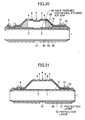
- FIG. 31 is a cross-sectional view schematically showing the configuration of a sixth embodiment of the Fabry-Perot filter according to the present invention.
- the Fabry-Perot filter described herein adopts the technical ideas recited in claims 22 to 31 of the present invention. Note that in FIG. 31, components identical to those of FIG. 27 are referenced alike and excluded from the explanation. In addition, the etching holes 6, which are otherwise present at the center of the movable mirror 4, are omitted from the figure for the purpose of simplifying the drawing.
- the Fabry-Perot filter of the sixth embodiment is fabricated in such a manner that in the second embodiment of the present invention, a backside protection layer laminated with protection layers 50 and 51 is formed in place of the protection layer 45.
- This backside protection layer is intended to protect the antireflection layer 44 when the sacrificial layer 41 is etched.
- the upper protection layer 50 is made of, for example, polysilicon and the lower protection layer 51 is made of, for example, silicon nitride.
- the backside protection layer in this embodiment is adaptable to any of the second to fifth embodiments.
- the metal-film aperture 46 is formed in contact with the protection layer 50, a residue of metal film may be produced when forming the optical area 47.
- the aperture 46 does not come into contact with the protection layer 50 if the protection layer 51 is inserted between the protection layer 50 and aperture 46. Consequently, no metal film residue will be produced in the optical area 47 and, therefore, the transmittance of light will improve, if the protection layer 51 is removed by wet etching during the formation of the optical area 47 and then the protection layer 50 is also etched away.
- the protection layer 45 is made of silicon nitride (second to fifth embodiments)
- the layer is also etched and the thickness thereof decreases as the sacrificial layer 41 is etched with a fluoric-acid etching liquid.
- This problem can be avoided, however, by inserting such a layer as a polysilicon layer, which is highly resistant to fluoric acids, as the protection layer 50. Consequently, the protection layer 50 serves as an etching stopper layer, thus preventing the antireflection layer 44 from being attacked by fluoric acid even if the silicon-nitride protection layer 51 is etched.
- the polysilicon composing the protection layer 50 can be easily removed by dry etching after the sacrificial layer 41 is etched, with the aperture 46 serving as the mask.
- the width of a gap is made to be variable in three steps. Consequently, it is possible to realize a Fabry-Perot filter for selectively admitting three wavelength bands of infrared radiation, including a wavelength band of reference light.
- the infrared gas analyzer of the present invention uses the Fabry-Perot filter of the present invention. Consequently, it is possible to simultaneously measure the concentrations of two constituents of the gas being measured, without having to increase the number of wavelength-selective filters. Thus, it is also possible to reduce both the size and cost of the infrared gas analyzer.
- the infrared gas analyzer uses the Fabry-Perot filter of the present invention and comprises a wide bandpass filter for admitting only a specific band of wavelengths. Consequently, it is possible to provide an infrared gas analyzer capable of measuring the concentrations of a plurality of gases by selecting only one peak for each width of a gap.
- a wavelength-selective filter and an infrared detector are integrated into one component, thereby ensuring the accuracy of fabrication. Consequently, it is possible to provide a small-sized, low-cost infrared gas analyzer.
- wavelength-selective infrared detectors are arranged in arrays. Consequently, it is possible to provide an infrared gas analyzer capable of measuring the concentrations of a multicomponent gas.
- the infrared gas analyzer uses the wavelength-selective infrared detector of the present invention. Consequently, it is possible to provide a small-sized, low-cost infrared gas analyzer.
- the infrared gas analyzer uses the wavelength-selective infrared detector of the present invention and comprises a wide bandpass filter for transmitting only a specific band of wavelengths. Consequently, it is possible to provide an infrared gas analyzer capable of measuring the concentrations of a plurality of gases by selecting only one peak for each width of a gap.
- the Fabry-Perot filter of the present invention is configured in such a manner that it is possible to broaden the stress design tolerance of a film composing the movable mirror, as well as reduce the dependency of the film upon film forming apparatus.
- Fabry-Perot filter of the present invention it is possible to prevent mirrors from being destroyed or fusing with each other in case, for example, a voltage above the given rating is applied across the mirrors.
- Fabry-Perot filter of the present invention it is possible to keep constant the size of a movable mirror (diaphragm) with high precision and, therefore, reduce the mirrorto-mirror variance of voltage at which desired widths of a gap are obtained.
Landscapes
- Physics & Mathematics (AREA)
- Spectroscopy & Molecular Physics (AREA)
- General Physics & Mathematics (AREA)
- Health & Medical Sciences (AREA)
- Life Sciences & Earth Sciences (AREA)
- Chemical & Material Sciences (AREA)
- Analytical Chemistry (AREA)
- Biochemistry (AREA)
- General Health & Medical Sciences (AREA)
- Immunology (AREA)
- Pathology (AREA)
- Spectrometry And Color Measurement (AREA)
- Investigating Or Analysing Materials By Optical Means (AREA)
Applications Claiming Priority (6)
| Application Number | Priority Date | Filing Date | Title |
|---|---|---|---|
| JP2000041288A JP4158076B2 (ja) | 2000-02-18 | 2000-02-18 | 波長選択型赤外線検出素子及び赤外線ガス分析計 |
| JP2000041288 | 2000-02-18 | ||
| JP2000041287A JP4457455B2 (ja) | 2000-02-18 | 2000-02-18 | ファブリペローフィルタ及び赤外線ガス分析計 |
| JP2000041287 | 2000-02-18 | ||
| JP2000371261 | 2000-12-06 | ||
| JP2000371261A JP2002174721A (ja) | 2000-12-06 | 2000-12-06 | ファブリペローフィルタ |
Publications (2)
| Publication Number | Publication Date |
|---|---|
| EP1126256A2 true EP1126256A2 (de) | 2001-08-22 |
| EP1126256A3 EP1126256A3 (de) | 2004-07-28 |
Family
ID=27342408
Family Applications (1)
| Application Number | Title | Priority Date | Filing Date |
|---|---|---|---|
| EP01103340A Withdrawn EP1126256A3 (de) | 2000-02-18 | 2001-02-13 | Fabry-Perot-Filter, wellenlängenselektiver Infrarotdetektor und einen solchen Filter/Detektor verwendender Infrarot-Gasanalysator |
Country Status (2)
| Country | Link |
|---|---|
| US (2) | US6590710B2 (de) |
| EP (1) | EP1126256A3 (de) |
Cited By (14)
| Publication number | Priority date | Publication date | Assignee | Title |
|---|---|---|---|---|
| WO2003087786A1 (en) * | 2002-04-08 | 2003-10-23 | Bae Systems Plc | Method and apparatus for gas detection |
| WO2004015783A1 (en) * | 2002-08-13 | 2004-02-19 | The University Of Western Australia | A resonant cavity enhanced device and a method for fabricating same |
| WO2006110041A1 (en) * | 2005-04-15 | 2006-10-19 | Sinvent As | Interference filter |
| WO2006110042A1 (en) * | 2005-04-15 | 2006-10-19 | Sinvent As | Adjustable interference filter |
| EP1882917A1 (de) | 2006-07-27 | 2008-01-30 | InfraTec GmbH Infrarotsensorik und Messtechnik | Durchstimmbares Dualband-Fabry-Perot-Filter |
| ITMI20092137A1 (it) * | 2009-12-03 | 2011-06-04 | Ribes Ricerche E Formazione S R L | Sensore di gas ad assorbimento ottico |
| US8053850B2 (en) | 2005-06-30 | 2011-11-08 | Semiconductor Energy Laboratory Co., Ltd. | Minute structure, micromachine, organic transistor, electric appliance, and manufacturing method thereof |
| EP2444791A1 (de) * | 2010-10-25 | 2012-04-25 | General Electric Company | Gasanalysegerät zur Messung von mindestens zwei Bestandteilen eines Gases |
| CN103513415A (zh) * | 2012-06-18 | 2014-01-15 | 株式会社电装 | 法布里-珀罗干涉仪 |
| US8638491B2 (en) | 2004-09-27 | 2014-01-28 | Qualcomm Mems Technologies, Inc. | Device having a conductive light absorbing mask and method for fabricating same |
| CN103776799A (zh) * | 2012-10-28 | 2014-05-07 | 天津奇谱光电技术有限公司 | 硫化氢气体传感设备 |
| US9086564B2 (en) | 2004-09-27 | 2015-07-21 | Qualcomm Mems Technologies, Inc. | Conductive bus structure for interferometric modulator array |
| US9945775B2 (en) | 2012-05-04 | 2018-04-17 | Isis Innovation Limited | Active chemical sensing using optical microcavity |
| US10732041B2 (en) | 2017-07-03 | 2020-08-04 | Teknologian Tutkimuskeskus Vtt Oy | Microelectromechanical (MEMS) fabry-perot interferometer, apparatus and method for manufacturing fabry-perot interferometer |
Families Citing this family (96)
| Publication number | Priority date | Publication date | Assignee | Title |
|---|---|---|---|---|
| JP2002207182A (ja) * | 2001-01-10 | 2002-07-26 | Sony Corp | 光学多層構造体およびその製造方法、光スイッチング素子、並びに画像表示装置 |
| US20070133001A1 (en) * | 2001-09-12 | 2007-06-14 | Honeywell International Inc. | Laser sensor having a block ring activity |
| US7145165B2 (en) * | 2001-09-12 | 2006-12-05 | Honeywell International Inc. | Tunable laser fluid sensor |
| US7015457B2 (en) * | 2002-03-18 | 2006-03-21 | Honeywell International Inc. | Spectrally tunable detector |
| US20050231800A1 (en) * | 2001-12-21 | 2005-10-20 | Barret Lippey | Selective reflecting |
| US7515336B2 (en) * | 2001-12-21 | 2009-04-07 | Bose Corporation | Selective reflecting |
| US6847483B2 (en) * | 2001-12-21 | 2005-01-25 | Bose Corporation | Selective reflecting |
| US7520624B2 (en) * | 2001-12-21 | 2009-04-21 | Bose Corporation | Light enhancing |
| US7196790B2 (en) * | 2002-03-18 | 2007-03-27 | Honeywell International Inc. | Multiple wavelength spectrometer |
| US7470894B2 (en) * | 2002-03-18 | 2008-12-30 | Honeywell International Inc. | Multi-substrate package assembly |
| GB0209531D0 (en) * | 2002-04-26 | 2002-06-05 | Glaxo Group Ltd | Medicament dispenser |
| US6958818B1 (en) * | 2002-12-18 | 2005-10-25 | Silicon Light Machines Corporation | Fabry-Perot interferometer including membrane supported reflector |
| US7233029B2 (en) * | 2003-01-17 | 2007-06-19 | Fujifilm Corporation | Optical functional film, method of forming the same, and spatial light modulator, spatial light modulator array, image forming device and flat panel display using the same |
| US7378655B2 (en) * | 2003-04-11 | 2008-05-27 | California Institute Of Technology | Apparatus and method for sensing electromagnetic radiation using a tunable device |
| DE10339319B4 (de) * | 2003-08-27 | 2013-02-07 | Robert Bosch Gmbh | Edelgasgefülltes Sensorelement für optische Sensoren |
| JP3979982B2 (ja) * | 2003-08-29 | 2007-09-19 | シャープ株式会社 | 干渉性変調器および表示装置 |
| JP3770326B2 (ja) * | 2003-10-01 | 2006-04-26 | セイコーエプソン株式会社 | 分析装置 |
| US7531363B2 (en) * | 2003-12-30 | 2009-05-12 | Honeywell International Inc. | Particle detection using fluorescence |
| JP4166712B2 (ja) | 2004-01-29 | 2008-10-15 | 株式会社デンソー | ファブリペローフィルタ |
| JP4409320B2 (ja) * | 2004-03-19 | 2010-02-03 | 日本航空電子工業株式会社 | 可変光利得等化器および光利得等化装置 |
| JP4504078B2 (ja) * | 2004-04-26 | 2010-07-14 | オリンパス株式会社 | エアギャップ可変式分光透過率可変素子のエアギャップ基準位置調整構造及びエアギャップ可変式分光透過率可変素子のエアギャップ基準位置調整構造を備えた光学装置 |
| JP4210245B2 (ja) * | 2004-07-09 | 2009-01-14 | セイコーエプソン株式会社 | 波長可変フィルタ及び検出装置 |
| KR100658114B1 (ko) * | 2004-09-17 | 2006-12-14 | 한국과학기술연구원 | 적외선 흡수층 구조와 형성 방법 및 이를 이용한 비냉각형적외선 감지소자 |
| US7586114B2 (en) | 2004-09-28 | 2009-09-08 | Honeywell International Inc. | Optical cavity system having an orthogonal input |
| US7902534B2 (en) | 2004-09-28 | 2011-03-08 | Honeywell International Inc. | Cavity ring down system having a common input/output port |
| JP4603489B2 (ja) * | 2005-01-28 | 2010-12-22 | セイコーエプソン株式会社 | 波長可変フィルタ |
| US7061660B1 (en) * | 2005-04-13 | 2006-06-13 | Hewlett-Packard Development Company, L.P. | MEMs device with feedback control |
| US7517091B2 (en) * | 2005-05-12 | 2009-04-14 | Bose Corporation | Color gamut improvement in presence of ambient light |
| US7276699B2 (en) * | 2005-05-18 | 2007-10-02 | Northrop Grumman Corporation | Absorptance enhancing coating for MWIR detectors |
| US7656532B2 (en) * | 2006-04-18 | 2010-02-02 | Honeywell International Inc. | Cavity ring-down spectrometer having mirror isolation |
| FI119830B (fi) * | 2006-05-24 | 2009-03-31 | Valtion Teknillinen | Spektrometri ja inferferometrinen menetelmä |
| US20100220331A1 (en) * | 2006-06-06 | 2010-09-02 | Anis Zribi | Micro-electromechanical system fabry-perot filter cavity |
| US7573578B2 (en) * | 2006-06-06 | 2009-08-11 | Ge Homeland Protection, Inc. | Micro-electromechanical system Fabry-Perot filter mirrors |
| US9291507B1 (en) | 2006-07-20 | 2016-03-22 | University Of South Florida | Differential capacitive readout system and method for infrared imaging |
| US20080049228A1 (en) * | 2006-08-28 | 2008-02-28 | Novaspectra, Inc. | Fabry-perot interferometer array |
| JP4432947B2 (ja) * | 2006-09-12 | 2010-03-17 | 株式会社デンソー | 赤外線式ガス検出器 |
| JP4356724B2 (ja) * | 2006-09-20 | 2009-11-04 | 株式会社デンソー | 赤外線式ガス検知装置およびそのガス検知方法 |
| JP4784495B2 (ja) * | 2006-11-28 | 2011-10-05 | 株式会社デンソー | 光学多層膜ミラーおよびそれを備えたファブリペロー干渉計 |
| US7649189B2 (en) | 2006-12-04 | 2010-01-19 | Honeywell International Inc. | CRDS mirror for normal incidence fiber optic coupling |
| US8081368B2 (en) * | 2007-03-29 | 2011-12-20 | Bose Corporation | Selective absorbing |
| US7710645B2 (en) * | 2007-06-29 | 2010-05-04 | Bose Corporation | Selective reflecting for laser projector |
| JP5224218B2 (ja) * | 2007-07-23 | 2013-07-03 | カール・ツァイス・エスエムティー・ゲーエムベーハー | マイクロリソグラフィ投影露光装置の光学システム |
| DE502007001810D1 (de) * | 2007-08-13 | 2009-12-03 | Infratec Gmbh | Anordnung und Verfahren zur Wellenlängen-Referenzierung von durchstimmbaren Fabry-Perot-Interferometern |
| US7844145B1 (en) * | 2008-04-14 | 2010-11-30 | The United States Of America As Represented By The Secretary Of The Navy | MEMS-based multi-channel Fabry-Perot interferometer system with increased tuning range and resolution |
| JP5266321B2 (ja) * | 2008-06-04 | 2013-08-21 | 旭化成エレクトロニクス株式会社 | 量子型赤外線センサおよびそれを用いた量子型赤外線ガス濃度計 |
| JP5251310B2 (ja) * | 2008-07-08 | 2013-07-31 | 日本電気株式会社 | 2波長熱型赤外線アレイセンサ |
| US7663756B2 (en) * | 2008-07-21 | 2010-02-16 | Honeywell International Inc | Cavity enhanced photo acoustic gas sensor |
| JP5176146B2 (ja) | 2008-10-08 | 2013-04-03 | 富士通株式会社 | マイクロ可動素子および光スイッチング装置 |
| JP5239722B2 (ja) * | 2008-10-10 | 2013-07-17 | 富士通株式会社 | マイクロ可動素子および光スイッチング装置 |
| US7864326B2 (en) | 2008-10-30 | 2011-01-04 | Honeywell International Inc. | Compact gas sensor using high reflectance terahertz mirror and related system and method |
| US8198590B2 (en) * | 2008-10-30 | 2012-06-12 | Honeywell International Inc. | High reflectance terahertz mirror and related method |
| DE102009011421B3 (de) * | 2009-03-03 | 2010-04-15 | Drägerwerk AG & Co. KGaA | Gaskonzentrationsmessvorrichtung |
| JP5798709B2 (ja) | 2009-03-04 | 2015-10-21 | セイコーエプソン株式会社 | 光フィルター及びそれを備えた光モジュール |
| US8107147B2 (en) * | 2009-03-27 | 2012-01-31 | Microvision, Inc. | Two-mirror scanning system |
| FI124072B (fi) * | 2009-05-29 | 2014-03-14 | Valtion Teknillinen | Mikromekaaninen säädettävä Fabry-Perot -interferometri, välituote ja menetelmä niiden valmistamiseksi |
| US8269972B2 (en) | 2010-06-29 | 2012-09-18 | Honeywell International Inc. | Beam intensity detection in a cavity ring down sensor |
| US8437000B2 (en) | 2010-06-29 | 2013-05-07 | Honeywell International Inc. | Multiple wavelength cavity ring down gas sensor |
| US8322191B2 (en) | 2010-06-30 | 2012-12-04 | Honeywell International Inc. | Enhanced cavity for a photoacoustic gas sensor |
| JP5531832B2 (ja) | 2010-07-06 | 2014-06-25 | セイコーエプソン株式会社 | 光フィルター、光フィルターモジュール、分光測定器および光機器 |
| JP2012042584A (ja) * | 2010-08-17 | 2012-03-01 | Seiko Epson Corp | 光フィルター、光フィルターモジュール、分光測定器および光機器 |
| JP5625614B2 (ja) * | 2010-08-20 | 2014-11-19 | セイコーエプソン株式会社 | 光フィルター、光フィルターモジュール、分光測定器および光機器 |
| JP5779852B2 (ja) * | 2010-08-25 | 2015-09-16 | セイコーエプソン株式会社 | 波長可変干渉フィルター、光モジュール、および光分析装置 |
| JP5707780B2 (ja) | 2010-08-25 | 2015-04-30 | セイコーエプソン株式会社 | 波長可変干渉フィルター、光モジュール、及び光分析装置 |
| JP5810512B2 (ja) * | 2010-11-12 | 2015-11-11 | セイコーエプソン株式会社 | 光学装置 |
| US9029783B2 (en) * | 2011-06-10 | 2015-05-12 | Flir Systems, Inc. | Multilayered microbolometer film deposition |
| JP2013057526A (ja) | 2011-09-07 | 2013-03-28 | Seiko Epson Corp | 赤外線検出素子、赤外線検出素子の製造方法及び電子機器 |
| GB2497296B (en) * | 2011-12-05 | 2017-07-12 | Gassecure As | Gas sensors |
| JP6003168B2 (ja) | 2012-04-11 | 2016-10-05 | セイコーエプソン株式会社 | 波長可変干渉フィルター、光学フィルターデバイス、光学モジュール、及び電子機器 |
| JP5987618B2 (ja) * | 2012-10-03 | 2016-09-07 | セイコーエプソン株式会社 | 波長可変干渉フィルター、光学フィルターデバイス、光学モジュール、及び電子機器 |
| CN103776792A (zh) * | 2012-10-28 | 2014-05-07 | 天津奇谱光电技术有限公司 | 一种使用可调谐法布里-珀罗滤波器的气体传感设备 |
| CN103776791A (zh) * | 2012-10-28 | 2014-05-07 | 天津奇谱光电技术有限公司 | 一氧化碳气体传感设备 |
| CN103048283B (zh) * | 2012-11-23 | 2015-03-18 | 姜利军 | 可调滤波器以及非色散气体探测器 |
| EP2857811B1 (de) | 2013-10-02 | 2015-09-23 | Sick Ag | Spektrometer zur Gasanalyse |
| US10113999B2 (en) * | 2014-03-07 | 2018-10-30 | City University Of Hong Kong | Method and a device for detecting a substance |
| CN106248224B (zh) * | 2015-06-09 | 2020-04-14 | 松下知识产权经营株式会社 | 光检测装置以及光检测系统 |
| JP6341959B2 (ja) * | 2016-05-27 | 2018-06-13 | 浜松ホトニクス株式会社 | ファブリペロー干渉フィルタの製造方法 |
| SG11201810376PA (en) * | 2016-05-27 | 2018-12-28 | Hamamatsu Photonics Kk | Production method for fabry-perot interference filter |
| US10405581B2 (en) * | 2016-07-08 | 2019-09-10 | Rai Strategic Holdings, Inc. | Gas sensing for an aerosol delivery device |
| CN109477959B (zh) * | 2016-08-24 | 2021-09-10 | 浜松光子学株式会社 | 法布里-珀罗干涉滤光器 |
| CN109477958A (zh) * | 2016-08-24 | 2019-03-15 | 浜松光子学株式会社 | 法布里-珀罗干涉滤光器 |
| JP2018205035A (ja) * | 2017-05-31 | 2018-12-27 | セイコーエプソン株式会社 | 分光システム、受光装置、生体情報測定装置および分光方法 |
| EP3640703B1 (de) * | 2017-06-13 | 2025-12-24 | Hamamatsu Photonics K.K. | Optisches filtersystem |
| US10901241B1 (en) | 2018-03-14 | 2021-01-26 | Onto Innovation Inc. | Optical metrology system using infrared wavelengths |
| US11990334B2 (en) * | 2019-07-19 | 2024-05-21 | Tokyo Electron Limited | Method for tuning stress transitions of films on a substrate |
| CN112415647B (zh) * | 2019-08-21 | 2024-10-11 | 新加坡国立大学 | 半导体标准具装置及制造方法 |
| US11932080B2 (en) | 2020-08-20 | 2024-03-19 | Denso International America, Inc. | Diagnostic and recirculation control systems and methods |
| US11828210B2 (en) | 2020-08-20 | 2023-11-28 | Denso International America, Inc. | Diagnostic systems and methods of vehicles using olfaction |
| US11881093B2 (en) | 2020-08-20 | 2024-01-23 | Denso International America, Inc. | Systems and methods for identifying smoking in vehicles |
| US12269315B2 (en) | 2020-08-20 | 2025-04-08 | Denso International America, Inc. | Systems and methods for measuring and managing odor brought into rental vehicles |
| US11760170B2 (en) | 2020-08-20 | 2023-09-19 | Denso International America, Inc. | Olfaction sensor preservation systems and methods |
| US11760169B2 (en) | 2020-08-20 | 2023-09-19 | Denso International America, Inc. | Particulate control systems and methods for olfaction sensors |
| US12377711B2 (en) | 2020-08-20 | 2025-08-05 | Denso International America, Inc. | Vehicle feature control systems and methods based on smoking |
| US11636870B2 (en) | 2020-08-20 | 2023-04-25 | Denso International America, Inc. | Smoking cessation systems and methods |
| US12251991B2 (en) | 2020-08-20 | 2025-03-18 | Denso International America, Inc. | Humidity control for olfaction sensors |
| US12017506B2 (en) | 2020-08-20 | 2024-06-25 | Denso International America, Inc. | Passenger cabin air control systems and methods |
| US11813926B2 (en) | 2020-08-20 | 2023-11-14 | Denso International America, Inc. | Binding agent and olfaction sensor |
Family Cites Families (11)
| Publication number | Priority date | Publication date | Assignee | Title |
|---|---|---|---|---|
| FR2639711B1 (fr) | 1988-11-25 | 1992-12-31 | Elf Aquitaine | Procede pour la detection simultanee de plusieurs gaz dans un melange gazeux, et appareillage pour la mise en oeuvre de ce procede |
| DE3925692C1 (de) | 1989-08-03 | 1990-08-23 | Hartmann & Braun Ag, 6000 Frankfurt, De | |
| US5225888A (en) | 1990-12-26 | 1993-07-06 | International Business Machines Corporation | Plasma constituent analysis by interferometric techniques |
| US5142414A (en) | 1991-04-22 | 1992-08-25 | Koehler Dale R | Electrically actuatable temporal tristimulus-color device |
| FI96450C (fi) | 1993-01-13 | 1996-06-25 | Vaisala Oy | Yksikanavainen kaasun pitoisuuden mittausmenetelmä ja -laitteisto |
| FI945124A0 (fi) | 1994-10-31 | 1994-10-31 | Valtion Teknillinen | Spektrometer |
| FI103216B1 (fi) * | 1995-07-07 | 1999-05-14 | Vaisala Oyj | Menetelmä NDIR-mittalaitteen lyhyen Fabry-Perot interferometrin ohjaamiseksi |
| US5920391A (en) * | 1995-10-27 | 1999-07-06 | Schlumberger Industries, S.A. | Tunable Fabry-Perot filter for determining gas concentration |
| US5831262A (en) * | 1997-06-27 | 1998-11-03 | Lucent Technologies Inc. | Article comprising an optical fiber attached to a micromechanical device |
| AU764799B2 (en) * | 1997-12-29 | 2003-08-28 | Coretek, Inc. | Microelectromechanically tunable, confocal, vertical cavity surface emitting laser and fabry-perot filter |
| US6438149B1 (en) * | 1998-06-26 | 2002-08-20 | Coretek, Inc. | Microelectromechanically tunable, confocal, vertical cavity surface emitting laser and fabry-perot filter |
-
2001
- 2001-02-05 US US09/777,901 patent/US6590710B2/en not_active Expired - Fee Related
- 2001-02-13 EP EP01103340A patent/EP1126256A3/de not_active Withdrawn
-
2002
- 2002-12-05 US US10/310,586 patent/US20030116711A1/en not_active Abandoned
Cited By (21)
| Publication number | Priority date | Publication date | Assignee | Title |
|---|---|---|---|---|
| WO2003087786A1 (en) * | 2002-04-08 | 2003-10-23 | Bae Systems Plc | Method and apparatus for gas detection |
| WO2004015783A1 (en) * | 2002-08-13 | 2004-02-19 | The University Of Western Australia | A resonant cavity enhanced device and a method for fabricating same |
| EP1535347A4 (de) * | 2002-08-13 | 2007-06-20 | Univ Western Australia | Resonatorerweiterte einrichtung und verfahren zu ihrer herstellung |
| US7541584B2 (en) | 2002-08-13 | 2009-06-02 | The University Of Western Australia | Resonant cavity enhanced device and a method for fabricating same |
| US8638491B2 (en) | 2004-09-27 | 2014-01-28 | Qualcomm Mems Technologies, Inc. | Device having a conductive light absorbing mask and method for fabricating same |
| US9097885B2 (en) | 2004-09-27 | 2015-08-04 | Qualcomm Mems Technologies, Inc. | Device having a conductive light absorbing mask and method for fabricating same |
| US9086564B2 (en) | 2004-09-27 | 2015-07-21 | Qualcomm Mems Technologies, Inc. | Conductive bus structure for interferometric modulator array |
| WO2006110041A1 (en) * | 2005-04-15 | 2006-10-19 | Sinvent As | Interference filter |
| WO2006110042A1 (en) * | 2005-04-15 | 2006-10-19 | Sinvent As | Adjustable interference filter |
| US7957004B2 (en) | 2005-04-15 | 2011-06-07 | Sinvent As | Interference filter |
| US8053850B2 (en) | 2005-06-30 | 2011-11-08 | Semiconductor Energy Laboratory Co., Ltd. | Minute structure, micromachine, organic transistor, electric appliance, and manufacturing method thereof |
| US8686405B2 (en) | 2005-06-30 | 2014-04-01 | Semiconductor Energy Laboratory Co., Ltd. | Minute structure, micromachine, organic transistor, electric appliance, and manufacturing method thereof |
| EP1882917A1 (de) | 2006-07-27 | 2008-01-30 | InfraTec GmbH Infrarotsensorik und Messtechnik | Durchstimmbares Dualband-Fabry-Perot-Filter |
| ITMI20092137A1 (it) * | 2009-12-03 | 2011-06-04 | Ribes Ricerche E Formazione S R L | Sensore di gas ad assorbimento ottico |
| US8642966B2 (en) | 2010-10-25 | 2014-02-04 | General Electric Company | Gas analyzer for measuring at least two components of a gas |
| CN102455286A (zh) * | 2010-10-25 | 2012-05-16 | 通用电气公司 | 用于测量气体的至少两种组分的气体分析器 |
| EP2444791A1 (de) * | 2010-10-25 | 2012-04-25 | General Electric Company | Gasanalysegerät zur Messung von mindestens zwei Bestandteilen eines Gases |
| US9945775B2 (en) | 2012-05-04 | 2018-04-17 | Isis Innovation Limited | Active chemical sensing using optical microcavity |
| CN103513415A (zh) * | 2012-06-18 | 2014-01-15 | 株式会社电装 | 法布里-珀罗干涉仪 |
| CN103776799A (zh) * | 2012-10-28 | 2014-05-07 | 天津奇谱光电技术有限公司 | 硫化氢气体传感设备 |
| US10732041B2 (en) | 2017-07-03 | 2020-08-04 | Teknologian Tutkimuskeskus Vtt Oy | Microelectromechanical (MEMS) fabry-perot interferometer, apparatus and method for manufacturing fabry-perot interferometer |
Also Published As
| Publication number | Publication date |
|---|---|
| US6590710B2 (en) | 2003-07-08 |
| US20010015810A1 (en) | 2001-08-23 |
| EP1126256A3 (de) | 2004-07-28 |
| US20030116711A1 (en) | 2003-06-26 |
Similar Documents
| Publication | Publication Date | Title |
|---|---|---|
| EP1126256A2 (de) | Fabry-Perot-Filter, wellenlängenselektiver Infrarotdetektor und einen solchen Filter/Detektor verwendender Infrarot-Gasanalysator | |
| US7679047B2 (en) | Infrared gas sensing apparatus and method | |
| TWI458944B (zh) | 感測器 | |
| EP3358320B1 (de) | Lichtdetektionsvorrichtung | |
| EP2181463B1 (de) | Pixelstruktur mit schirmartigem absorber mit einem oder mehreren vertiefungen bzw. kanälen für erhöhte strahlenabsorption | |
| JP4158076B2 (ja) | 波長選択型赤外線検出素子及び赤外線ガス分析計 | |
| EP0693683A1 (de) | Selektiver Infrarotdetektor | |
| EP3023767A1 (de) | Interferometrische vorrichtung zur detektierung einer substanz, und ein verfahren zu deren herstellung | |
| US6344647B1 (en) | Miniaturized photoacoustic spectrometer | |
| JP7047161B2 (ja) | 光検出装置 | |
| EP3591358B1 (de) | Lichtdetektionsvorrichtung | |
| TWI825876B (zh) | 晶圓 | |
| US7470894B2 (en) | Multi-substrate package assembly | |
| Neumann et al. | Tunable infrared detector with integrated micromachined Fabry-Perot filter | |
| JP4457455B2 (ja) | ファブリペローフィルタ及び赤外線ガス分析計 | |
| CN112415647B (zh) | 半导体标准具装置及制造方法 | |
| WO2019102880A1 (ja) | 電気的検査方法 | |
| JP7202160B2 (ja) | 光学フィルタ装置、及び光学フィルタ装置の制御方法 | |
| JP5515314B2 (ja) | 波長選択型赤外線検出器 | |
| JP7640496B2 (ja) | フィルタ装置 | |
| KR100453975B1 (ko) | 초소형 자기력 구동 패브리-페롯 필터 및 그를 이용한가스 분석 장치 | |
| JP2001228086A (ja) | 赤外線ガス分析計 | |
| JP2026501971A (ja) | 微細加工されたトップハット型波長調整フィルタ | |
| Neumann et al. | Multi-Colour and Tunable-Colour Pyroelectric Detectors | |
| JP2018155645A (ja) | 分光フィルタユニットおよび分光測光装置 |
Legal Events
| Date | Code | Title | Description |
|---|---|---|---|
| PUAI | Public reference made under article 153(3) epc to a published international application that has entered the european phase |
Free format text: ORIGINAL CODE: 0009012 |
|
| AK | Designated contracting states |
Kind code of ref document: A2 Designated state(s): AT BE CH CY DE DK ES FI FR GB GR IE IT LI LU MC NL PT SE TR |
|
| AX | Request for extension of the european patent |
Free format text: AL;LT;LV;MK;RO;SI |
|
| RIC1 | Information provided on ipc code assigned before grant |
Ipc: 7G 01N 21/35 B Ipc: 7G 01J 3/26 A |
|
| PUAL | Search report despatched |
Free format text: ORIGINAL CODE: 0009013 |
|
| RIC1 | Information provided on ipc code assigned before grant |
Ipc: 7B 81B 3/00 B Ipc: 7G 01N 21/35 B Ipc: 7G 01J 3/26 A |
|
| AK | Designated contracting states |
Kind code of ref document: A3 Designated state(s): AT BE CH CY DE DK ES FI FR GB GR IE IT LI LU MC NL PT SE TR |
|
| AX | Request for extension of the european patent |
Extension state: AL LT LV MK RO SI |
|
| 17P | Request for examination filed |
Effective date: 20041027 |
|
| AKX | Designation fees paid |
Designated state(s): DE GB NL |
|
| 17Q | First examination report despatched |
Effective date: 20060706 |
|
| STAA | Information on the status of an ep patent application or granted ep patent |
Free format text: STATUS: THE APPLICATION HAS BEEN WITHDRAWN |
|
| 18W | Application withdrawn |
Effective date: 20071022 |