EP1126115A2 - Gelenkband mit selbsthemmendem Exzenterverstellantrieb - Google Patents
Gelenkband mit selbsthemmendem Exzenterverstellantrieb Download PDFInfo
- Publication number
- EP1126115A2 EP1126115A2 EP01101898A EP01101898A EP1126115A2 EP 1126115 A2 EP1126115 A2 EP 1126115A2 EP 01101898 A EP01101898 A EP 01101898A EP 01101898 A EP01101898 A EP 01101898A EP 1126115 A2 EP1126115 A2 EP 1126115A2
- Authority
- EP
- European Patent Office
- Prior art keywords
- eccentric
- recess
- cylindrical
- hinge
- adjustment
- Prior art date
- Legal status (The legal status is an assumption and is not a legal conclusion. Google has not performed a legal analysis and makes no representation as to the accuracy of the status listed.)
- Granted
Links
Images
Classifications
-
- E—FIXED CONSTRUCTIONS
- E05—LOCKS; KEYS; WINDOW OR DOOR FITTINGS; SAFES
- E05D—HINGES OR SUSPENSION DEVICES FOR DOORS, WINDOWS OR WINGS
- E05D7/00—Hinges or pivots of special construction
- E05D7/04—Hinges adjustable relative to the wing or the frame
- E05D7/0415—Hinges adjustable relative to the wing or the frame with adjusting drive means
-
- E—FIXED CONSTRUCTIONS
- E05—LOCKS; KEYS; WINDOW OR DOOR FITTINGS; SAFES
- E05D—HINGES OR SUSPENSION DEVICES FOR DOORS, WINDOWS OR WINGS
- E05D5/00—Construction of single parts, e.g. the parts for attachment
- E05D5/02—Parts for attachment, e.g. flaps
- E05D5/04—Flat flaps
Definitions
- the invention relates to an adjustable hinge for doors or windows, with a frame hinge part to be attached to the frame and a Wing to be attached to the wing hinge part, which is articulated with the frame hinge part is connected and consists of an abutment part which can be fixed on the wing and an adjustment part, the adjustment part compared to the Abutment part in a horizontal, perpendicular to the joint axis Direction of displacement is guided by means of a counter the abutment part supported self-locking adjustment drive continuously is adjustable and can be locked by means of at least one locking screw, wherein the adjustment drive comprises an eccentric which one in one Recess of the adjusting part rotatably held cylindrical part and an eccentric for this purpose, which engages in an elongated hole of the abutment part, has cylindrical eccentric.
- An adjustable hinge strap of this type is known from the EP 0 652 345 A1.
- the well-known hinge is made by an eccentric set via a cylindrical coaxial to the axis of rotation of the eccentric Body is rotatably mounted in the adjustment part and is eccentric arranged to the axis of rotation cylindrical eccentric in engages a cylindrical recess of a sliding block, the Sliding block in turn in the slot of the abutment part with little Play is guided.
- This causes in the slot of the Abutment slidably guided sliding block the self-locking of the Actuator. Due to the weight of the door or window sash a moment arises which is hinged on one side Wing rotates around its center.
- a door or window hinge is also known from EP 0 259 618 Lateral adjustment is effected by means of an eccentric. With this wrist band the eccentric is not in the adjustment part, but in the abutment part rotatably added. The eccentric pin engages in an elongated hole in the Adjustment part to effect the side adjustment.
- a wrist band with these features emerge from the preamble of claim 2.
- the main disadvantage of the side adjustment device of this hinge is that they have hardly any self-locking properties due to the lack of sliding block having. When loosening the locking screw to adjust the Side distance between the wing and the frame of the eccentric burdened by the force due to the wing weight and can easily turn from its set position to a stop position. The consequence is that the wing needs to be completely realigned.
- the invention has for its object to provide an adjustable hinge a sufficient self-locking effect of the adjustment drive to create released locking screw, which has few components and is therefore inexpensive and can be manufactured with a small size.
- the recess at least one base pair to support the peripheral surface of the forms cylindrical part of the eccentric, the two bases of the Base pairs on the same side of the vertical median plane and too lie on both sides of the horizontal central plane of the recess.
- the recess has a pair of support points, which due to the pulling force of the sash weight is self-locking of the adjusting drive exerting clamping force on the eccentric.
- the Recess forms at least on the side against which the eccentric released locking screw is pressed due to the sash weight Base pair, whose base is a certain angular distance from the upper and lower vertices of the cylindrical part of the eccentric exhibit.
- the contact surface of the recess in the essentially a plane that is tangential to the peripheral surface of the cylindrical part of the eccentric, so that strictly speaking in each Base creates a line-shaped contact area.
- the term "base” thus refers the contact area in a certain angular position of the recess, which keeps the cylindrical part of the eccentric rotatable, regardless of the exact shape of the contact area.
- the cylindrical part of the eccentric is therefore over defined support points and not through a complementary cylindrical inner surface of the recess supported.
- a supporting force can essentially only in the radial direction on the peripheral surface of the cylindrical part of the eccentric.
- the force vector in the bases that are essentially opposite each other in the vertical direction together from the horizontal components that are parallel to the direction of displacement act and balance the forces due to the wing weight, and the vertical force components.
- the vertical force components are internal forces in the cylindrical part of the eccentric each for a base pair and the size of the The angular position of the two support points results because the effective direction of the total force in every base - as I said - must run radially.
- a base pair is arranged on the side of the recess.
- a third Base to be provided on the opposite side, e.g. in the area of horizontal Central plane of the cylindrical part of the eccentric.
- the base pair and the third base form a triangle, in the corners of which the support points for the cylindrical Part of the eccentric.
- Such a recording is sufficient to to guide cylindrical part stationary but rotatable. In the other areas the peripheral surface of the cylindrical part is no further contact with the Recess required.
- the recess can therefore only by wall sections be formed in these three bases.
- the wrist band can thus be used as both an upper and a lower hinge and for the right stop as well as for the Left stop of the wing can be used.
- To these two cylindrical wall sections close tangentially to the peripheral surface of the cylindrical part extending wall sections. Any transition area between the end of a cylindrical wall section and one tangential wall section forms a base.
- the one on the same side with respect to the vertical median plane of the recess lying transition areas between the cylindrical wall sections and the tangential wall sections form a base pair.
- the parts of the wing hinge part namely the adjustment part, are preferred the abutment part and the eccentric are made as zinc die-cast parts.
- the coefficient of friction of this material leads to optimal self-locking of the eccentric with sufficient ease of adjustment using an adjustment tool if the two bases of a base pair an angular distance of 20 to 30 ° to the vertical central plane of the Have recess for the cylindrical portion. This results in in the embodiment with two tangential wall sections an angle of 40 ° to 60 °, the top view of the tangential wall sections is included.
- the eccentric preferably has a hexagon recess for a hexagon wrench on.
- On the outside of the adjustment part can - how in the prior art mentioned at the outset - a display marking with be attached to a scale on which by means of a pointer on the eccentric the current adjustment position of the eccentric can be read.
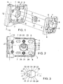
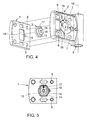
- the wing hinge part shown in the drawings is composed an abutment part 1, an adjustment part 2 and an eccentric 3 Abutment part 1 is with its recognizable in Fig. 1 back put a door or window wing, two trunnions 4 holes stick out in the wing.
- On the abutment part 1 is in between Eccentric 3 the adjustment part 2 is placed, it being the upper and lower Walls around the abutment part 1 with little play and thereby is guided horizontally on the abutment part.
- the adjustment part 2 has elongated holes 6.7, each of which has a locking screw (not shown) are penetrated, either in the wing itself or in Tapped holes 8 of the abutment part 1 are screwed, the Screw heads of the locking screws the adjustment part 2 opposite Fix abutment part 1 or opposite the wing.
- the adjustment part 2 has a pin receptacle 9 for the pivot pin of the Wrist band on.
- the hinge axis 10 of the pin receptacle 9 runs in vertical direction.
- the one that protrudes downward from the pin receptacle Pin section is attached to the frame in a pin bearing Frame hinge part (not shown) rotatably added.
- the eccentric 3 comprises a cylindrical part 11 which is in a recess 12 is inserted in the rear wall of the adjustment part 2.
- a hollow eccentric pin 13 is formed on the central axis.
- the eccentric pin 13 engages in a slot 14 of the abutment part 1 with little play.
- the elongated hole 14 is a pocket formed, on the rear wall of the support pins 4 are arranged.
- a cylindrical projection 15 is formed with a reduced diameter.
- the cylindrical projection 15 has a hexagon recess 16 for a hexagon adjustment key (also called INBUS® key).
- a radial projection 17 is also formed on it.
- the cylindrical Projection 15 and the radial projection 17 protrude through a recess 18 in the middle of the adjustment part 2 with sufficient play so that a contact is avoided in the radial direction. So the eccentric 3 is only supported its cylindrical part 11 against the rear recess 12 in Adjustment part 2.
- the recess 18 essentially comprises two each other diametrically opposite shoulders, which is a stop for the form radial projection 17 of the eccentric 3 and thus the adjustment range of the eccentric 3.
- an adjustment scale 19 which in connection with the radial projection 17 of the eccentric 3, the adjustment position of the adjustment part 2 opposite the abutment part 1 indicates.
- the eccentric 3 has no contact to recess 18, except for the radial shoulders of this recess 18.
- the eccentric 3 is exclusive through its cylindrical part 11 in the recess 12 of the Adjustment part 2 held.
- the recess 12 settles, as in particular in 2 and 3 recognizable, from an upper cylindrical section Wall section 20 and a corresponding lower wall section 21 as well as four adjoining these cylindrical wall sections 20, 21 tangential wall sections 22-25 together.
- At a distance from the cylindrical Part 11 of the eccentric 3 run two the ends of the tangential Vertical wall sections 26 and 27 connecting wall sections 22-25.
- the cylindrical part 11 is between the upper tangential surface 22 and the lower tangential Surface 24 clamped so that there is increased friction, which self-locking of the eccentric adjustment drive against twisting a force acting horizontally to the right.
- the support points 30, 31 cause pinching of the cylindrical part.
- the clamping effect of the base pair can be 28.29 and 30.31 respectively by placing the support points 28 - 31 closer to the vertical center plane 32 of the recess 12 can be moved.
- the support points 28 - 31 are in a circular extension of the cylindrical section-shaped wall sections 20, 21 to the horizontal center plane 33 of the recess 12 displaced, the clamping force is reduced and thus the self-locking effect of the eccentric drive. Consequently can - as already mentioned - by optimally choosing the location of the bases 28 - 31 a self-locking effect can be achieved, which is certainly an unintended Rotation of the eccentric 3 due to the applied by the wing Forces prevented, but at the same time twisting of the eccentric 3 by means of an adjustment tool without excessive force enables.
Landscapes
- Engineering & Computer Science (AREA)
- Mechanical Engineering (AREA)
- Hinges (AREA)
- Devices For Conveying Motion By Means Of Endless Flexible Members (AREA)
Abstract
Description
- Fig. 1
- eine räumliche Rückansicht der Teile des Flügelbandteils,
- Fig. 2
- eine Rückansicht des Verstellteils mit in die Ausnehmung eingefügtem Exzenter,
- Fig. 3
- eine Draufsicht auf die Kontur der Ausnehmung in der Rückwand des Verstellteils aus den Figuren 1 und 2,
- Fig. 4
- eine räumliche Draufsicht auf die Teile des Flügelbandteils und
- Fig. 5
- eine Draufsicht auf das Widerlagerteil mit in das Langloch eingreifendem Exzenter.
- 1
- Widerlagerteil
- 2
- Verstellteil
- 3
- Exzenter
- 4
- Tragzapfen
- 5
- Schraubloch
- 6
- Langloch
- 7
- Langloch
- 8
- Gewindebohrung
- 9
- Zapfenaufnahme
- 10
- Gelenkachse
- 11
- zylindrischer Teil des Exzenters
- 12
- Ausnehmung
- 13
- Exzenterzapfen
- 14
- Langloch
- 15
- zylindrischer Vorsprung
- 16
- Sechskantausnehmung
- 17
- radialer Vorsprung
- 18
- Aussparung
- 19
- Verstellskala
- 20
- zylindrischer Wandabschnitt
- 21
- zylindrischer Wandabschnitt
- 22-25
- tangentialer Wandabschnitt
- 26-27
- vertikaler Wandabschnitt
- 28-31
- Stützpunkt
- 32
- vertikale Mittelebene
- 33
- horizontale Mittelebene
- α
- Winkel zwischen tangentialen Wandabschnitten
Claims (6)
- Einstellbares Gelenkband für Türen oder Fenster, mit einem am Rahmen zu befestigenden Rahmenbandteil und einem am Flügel zu befestigenden Flügelbandteil, das gelenkig mit dem Rahmenbandteil verbunden ist und sich aus einem am Flügel festlegbaren Widerlagerteil (1) und einem Verstellteil (2) zusammensetzt, wobei das Verstellteil (2) gegenüber dem Widerlagerteil (1) in einer rechtwinklig zur Gelenkachse (10) verlaufenden, horizontalen Verschieberichtung verschiebbar geführt ist, mittels eines gegen das Widerlagerteil (1) abgestützten selbsthemmenden Verstellantriebes stufenlos einstellbar und mittels mindestens einer Feststellschraube feststellbar ist, wobei der Verstellantrieb einen Exzenter (3) umfaßt, welcher einen in einer Ausnehmung (12) des Verstellteils (2) drehbar gehaltenen zylindrischen Teil (11) und einen hierzu exzentrischen, in ein Langloch (14) des Widerlagerteils (1) eingreifenden, zylindrischen Exzenterzapfen (13) aufweist, dadurch gekennzeichnet, daß die Ausnehmung (12) mindestens ein Stützpunkte-Paar (28,29 bzw. 30,31) zur Abstützung der Umfangsfläche des zylindrischen Teils (11) des Exzenters (3) bildet, wobei die beiden Stützpunkte (28,29 oder 30,31) des Stützpunkte-Paars auf der gleichen Seite der vertikalen Mittelebene (32) und zu beiden Seiten der horizontalen Mittelebene (33) der Ausnehmung (12) liegen.
- Einstellbares Gelenkband für Türen oder Fenster, mit einem am Rahmen zu befestigenden Rahmenbandteil und einem am Flügel zu befestigenden Flügelbandteil, das gelenkig mit dem Rahmenbandteil verbunden ist und sich aus einem am Flügel festlegbaren Widerlagerteil und einem Verstellteil zusammensetzt, wobei das Verstellteil gegenüber dem Widerlagerteil in einer rechtwinklig zur Gelenkachse verlaufenden, horizontalen Verschieberichtung verschiebbar geführt ist, mittels eines gegen das Widerlagerteil abgestützten selbsthemmenden Verstellantriebes stufenlos einstellbar und mittels mindestens einer Feststellschraube feststellbar ist, wobei der Verstellantrieb einen Exzenter umfaßt, welcher einen in einer Ausnehmung des Widerlagerteils drehbar gehaltenen zylindrischen Teil und einen hierzu exzentrischen, in ein Langloch des Verstellteils eingreifenden, zylindrischen Exzenterzapfen aufweist, dadurch gekennzeichnet, daß die Ausnehmung (12) mindestens ein Stützpunkte-Paar (28,29 bzw. 30,31) zur Abstützung der Umfangsfläche des zylindrischen Teils (11) des Exzenters (3) bildet, wobei die beiden Stützpunkte (28,29 oder 30,31) des Stützpunkte-Paars auf der gleichen Seite der vertikalen Mittelebene (32) und zu beiden Seiten der horizontalen Mittelebene (33) der Ausnehmung (12) liegen.
- Einstellbares Gelenkband nach Anspruch 1 oder 2, dadurch gekennzeichnet, daß die Ausnehmung (12) zu beiden Seiten der vertikalen Mittelebene (32) der Ausnehmung (12) jeweils ein Stützpunkte-Paar (28,29 und 30,31) aufweist.
- Einstellbares Gelenkband nach einem der Ansprüche 1 bis 3, dadurch gekennzeichnet, daß die Ausnehmung (12) einen oberen und einen unteren, den zylindrischen Teil (11) des Exzenters (3) mit geringem Spiel umgreifenden Wandabschnitt (20 und 21) umfaßt, wobei sich an diese zylindrischen Wandabschnitte (20,21) tangential zur Umfangsfläche des zylindrischen Teils (11) verlaufende Wandabschnitte (22,23,24,25) anschließen und wobei die auf einer Seite der vertikalen Mittelebene (32) der Ausnehmung (12) liegenden Übergangsbereiche zwischen den zylindrischen Wandabschnitten (20,21) und den tangentialen Wandabschnitten (22,24 bzw. 23,25) ein Stützpunkte-Paar (29,29 bzw. 30,31) bilden.
- Einstellbares Gelenkband nach Anspruch 4, dadurch gekennzeichnet, daß der Winkel (α) zwischen zwei tangentialen Wandabschnitten (22,24 bzw. 23,25) auf einer Seite der vertikalen Mittelebene (32) der Ausnehmung (12) zwischen 40° und 60° liegt.
- Einstellbares Gelenkband nach einem der vorangehenden Ansprüche, dadurch gekennzeichnet, daß der Exzenter (3) eine Sechskantausnehmung (16) für den Eingriff eines Sechskant-Verstellschlüssels aufweist.
Applications Claiming Priority (2)
| Application Number | Priority Date | Filing Date | Title |
|---|---|---|---|
| DE20002472 | 2000-02-11 | ||
| DE20002472U | 2000-02-11 |
Publications (3)
| Publication Number | Publication Date |
|---|---|
| EP1126115A2 true EP1126115A2 (de) | 2001-08-22 |
| EP1126115A3 EP1126115A3 (de) | 2007-03-21 |
| EP1126115B1 EP1126115B1 (de) | 2009-04-22 |
Family
ID=7937188
Family Applications (1)
| Application Number | Title | Priority Date | Filing Date |
|---|---|---|---|
| EP01101898A Expired - Lifetime EP1126115B1 (de) | 2000-02-11 | 2001-01-27 | Gelenkband mit selbsthemmendem Exzenterverstellantrieb |
Country Status (4)
| Country | Link |
|---|---|
| EP (1) | EP1126115B1 (de) |
| AT (1) | ATE429561T1 (de) |
| DE (1) | DE50114845D1 (de) |
| ES (1) | ES2326157T3 (de) |
Cited By (9)
| Publication number | Priority date | Publication date | Assignee | Title |
|---|---|---|---|---|
| WO2004018815A1 (de) | 2002-08-05 | 2004-03-04 | Dr. Hahn Gmbh & Co. Kg | Bandteil für ein band für türen, fenster und dergleichen |
| DE20217852U1 (de) * | 2002-11-19 | 2004-04-01 | Dr. Hahn Gmbh & Co. Kg | Band für Türen, Fenster o.dgl. |
| EP1611832A1 (de) * | 2004-07-01 | 2006-01-04 | Bonferraro S.p.A. | Vorrichtung zur Befestigung einer Dekorplatte an eine Struktur |
| DE102007043757B3 (de) * | 2007-09-13 | 2008-11-20 | Schüring GmbH & Co. Fenster-Technologie KG | Verstellbares Flügelbandteil eines Gelenkbandes |
| EP1997991A2 (de) | 2007-06-01 | 2008-12-03 | Schüring GmbH & Co. Fenster-Technologie KG | Gelenkband für Türen oder Fenster |
| EP2042674A1 (de) * | 2007-09-28 | 2009-04-01 | Etablissements Tordo-Belgrano | Vorrichtung zur Montage eines Bewegungsbeschlags für Tür- oder Fensterflügel auf einem Scharnier |
| EP2927407A1 (de) * | 2014-04-02 | 2015-10-07 | Heywood Williams Components Limited | Scharnier |
| AU2014218417B2 (en) * | 2013-09-02 | 2018-11-29 | Mammoth Industries Pty Ltd | A hinge and method of installation |
| CN111236866A (zh) * | 2020-03-04 | 2020-06-05 | 四川宏华石油设备有限公司 | 一种铁钻工钳体调平机构 |
Families Citing this family (1)
| Publication number | Priority date | Publication date | Assignee | Title |
|---|---|---|---|---|
| CN113653416B (zh) * | 2021-09-13 | 2023-03-28 | 希美克(广州)实业有限公司 | 一种可调式框扇合页装置 |
Citations (2)
| Publication number | Priority date | Publication date | Assignee | Title |
|---|---|---|---|---|
| EP0259618A2 (de) | 1986-08-13 | 1988-03-16 | Gebr. Brotschi & Co. AG | Während und nach der Montage verstellbares Tür- und Fensterband |
| EP0652345A1 (de) | 1993-11-08 | 1995-05-10 | Schüring GmbH & Co. Fenstertechnologie KG | Einstellbares Gelenkband für Türen oder Fenster |
-
2001
- 2001-01-27 EP EP01101898A patent/EP1126115B1/de not_active Expired - Lifetime
- 2001-01-27 AT AT01101898T patent/ATE429561T1/de not_active IP Right Cessation
- 2001-01-27 DE DE50114845T patent/DE50114845D1/de not_active Expired - Lifetime
- 2001-01-27 ES ES01101898T patent/ES2326157T3/es not_active Expired - Lifetime
Patent Citations (2)
| Publication number | Priority date | Publication date | Assignee | Title |
|---|---|---|---|---|
| EP0259618A2 (de) | 1986-08-13 | 1988-03-16 | Gebr. Brotschi & Co. AG | Während und nach der Montage verstellbares Tür- und Fensterband |
| EP0652345A1 (de) | 1993-11-08 | 1995-05-10 | Schüring GmbH & Co. Fenstertechnologie KG | Einstellbares Gelenkband für Türen oder Fenster |
Cited By (14)
| Publication number | Priority date | Publication date | Assignee | Title |
|---|---|---|---|---|
| WO2004018815A1 (de) | 2002-08-05 | 2004-03-04 | Dr. Hahn Gmbh & Co. Kg | Bandteil für ein band für türen, fenster und dergleichen |
| DE20217852U1 (de) * | 2002-11-19 | 2004-04-01 | Dr. Hahn Gmbh & Co. Kg | Band für Türen, Fenster o.dgl. |
| EP1611832A1 (de) * | 2004-07-01 | 2006-01-04 | Bonferraro S.p.A. | Vorrichtung zur Befestigung einer Dekorplatte an eine Struktur |
| EP1997991A3 (de) * | 2007-06-01 | 2011-12-21 | Schüring GmbH & Co. Fenster-Technologie KG | Gelenkband für Türen oder Fenster |
| EP1997991A2 (de) | 2007-06-01 | 2008-12-03 | Schüring GmbH & Co. Fenster-Technologie KG | Gelenkband für Türen oder Fenster |
| DE102007025857A1 (de) | 2007-06-01 | 2008-12-04 | Schüring GmbH & Co. Fenster-Technologie KG | Gelenkband für Türen oder Fenster |
| EP2037066A2 (de) | 2007-09-13 | 2009-03-18 | Schüring GmbH & Co. Fenstertechnologie KG | Verstellbares Flügelbandteil |
| DE102007043757B3 (de) * | 2007-09-13 | 2008-11-20 | Schüring GmbH & Co. Fenster-Technologie KG | Verstellbares Flügelbandteil eines Gelenkbandes |
| EP2037066A3 (de) * | 2007-09-13 | 2012-03-07 | Schüring GmbH & Co. Fenstertechnologie KG | Verstellbares Flügelbandteil |
| EP2042674A1 (de) * | 2007-09-28 | 2009-04-01 | Etablissements Tordo-Belgrano | Vorrichtung zur Montage eines Bewegungsbeschlags für Tür- oder Fensterflügel auf einem Scharnier |
| AU2014218417B2 (en) * | 2013-09-02 | 2018-11-29 | Mammoth Industries Pty Ltd | A hinge and method of installation |
| EP2927407A1 (de) * | 2014-04-02 | 2015-10-07 | Heywood Williams Components Limited | Scharnier |
| CN104975774A (zh) * | 2014-04-02 | 2015-10-14 | 海伍德·威廉姆斯零件有限公司 | 铰链 |
| CN111236866A (zh) * | 2020-03-04 | 2020-06-05 | 四川宏华石油设备有限公司 | 一种铁钻工钳体调平机构 |
Also Published As
| Publication number | Publication date |
|---|---|
| ES2326157T3 (es) | 2009-10-02 |
| ATE429561T1 (de) | 2009-05-15 |
| EP1126115A3 (de) | 2007-03-21 |
| EP1126115B1 (de) | 2009-04-22 |
| DE50114845D1 (de) | 2009-06-04 |
Similar Documents
| Publication | Publication Date | Title |
|---|---|---|
| EP0259618B1 (de) | Während und nach der Montage verstellbares Tür- und Fensterband | |
| AT6962U1 (de) | Scharnier | |
| DE4219681A1 (de) | Einstellbares abhebescharnier | |
| EP0285229B2 (de) | Einstellbares Gelenkband, insbesondere für Türen | |
| EP1126115B1 (de) | Gelenkband mit selbsthemmendem Exzenterverstellantrieb | |
| AT402086B (de) | Beschlag für türen, fenster oder dergleichen | |
| CH687717A5 (de) | Tuer- oder Fensterband. | |
| EP2345787B1 (de) | Türband für Aluminiumtüren | |
| DE102010004771B3 (de) | Türband für Aluminiumtüren | |
| EP0837206B1 (de) | Türscharnier zur schwenkbaren Lagerung eines Türflügels an einem Türrahmen | |
| EP0470601A1 (de) | Gerät zum Anbringen der Bohrungen zum Befestigen der Rahmenbandteile eines Fensters oder einer Türe | |
| DE1810671B2 (de) | Stelleinrichtung an Fenstern,Tueren od.dgl. | |
| EP0723058B1 (de) | Bremse, insbesondere für einen Oberlichtflügel | |
| DE29817807U1 (de) | Dreidimensional verstellbares Aufschraubband für Tür- oder Fensterflügel | |
| EP0487825B1 (de) | Verdeckt angeordneter Beschlag für Drehflügel, insb. für Dreh-Kipp-Flügel von Fenstern oder Türen | |
| EP0893564A2 (de) | Drehlager für Fenster oder Türen | |
| DE2524454C3 (de) | Scharnier für rahmenlose Türen aus Glas | |
| EP1563152B1 (de) | Gelenkband | |
| DE102017212714B3 (de) | Gelenkband für ein Trennelement | |
| EP0704593B1 (de) | Dreh-Beschlag oder Dreh-Kipp-Beschlag von Fenster, Türen oder dergleichen mit verrastbarem Exzenterteil zum Einstellen einer horizontalen Falzluft und/oder eines Flügelanpressdrucks zwischen Festrahmen und/oder Flügelrahmen | |
| DE19832025B4 (de) | Höhenverstellbares Gelenkband | |
| DE3117118A1 (de) | Scharnier, insbesondere fuer tueren, wie tueren von sicherungs- oder schaltkaesten | |
| DE10150916B4 (de) | Gelenkband, insbesondere für Glaspendeltüren | |
| DE19940132C2 (de) | Gelenkband | |
| EP0671531B1 (de) | Scharnier |
Legal Events
| Date | Code | Title | Description |
|---|---|---|---|
| PUAI | Public reference made under article 153(3) epc to a published international application that has entered the european phase |
Free format text: ORIGINAL CODE: 0009012 |
|
| AK | Designated contracting states |
Kind code of ref document: A2 Designated state(s): AT BE CH CY DE DK ES FI FR GB GR IE IT LI LU MC NL PT SE TR |
|
| AX | Request for extension of the european patent |
Free format text: AL;LT;LV;MK;RO;SI |
|
| PUAL | Search report despatched |
Free format text: ORIGINAL CODE: 0009013 |
|
| AK | Designated contracting states |
Kind code of ref document: A3 Designated state(s): AT BE CH CY DE DK ES FI FR GB GR IE IT LI LU MC NL PT SE TR |
|
| AX | Request for extension of the european patent |
Extension state: AL LT LV MK RO SI |
|
| 17P | Request for examination filed |
Effective date: 20070404 |
|
| 17Q | First examination report despatched |
Effective date: 20070816 |
|
| AKX | Designation fees paid |
Designated state(s): AT BE CH CY DE DK ES FI FR GB GR IE IT LI LU MC NL PT SE TR |
|
| GRAP | Despatch of communication of intention to grant a patent |
Free format text: ORIGINAL CODE: EPIDOSNIGR1 |
|
| GRAS | Grant fee paid |
Free format text: ORIGINAL CODE: EPIDOSNIGR3 |
|
| GRAA | (expected) grant |
Free format text: ORIGINAL CODE: 0009210 |
|
| AK | Designated contracting states |
Kind code of ref document: B1 Designated state(s): AT BE CH CY DE DK ES FI FR GB GR IE IT LI LU MC NL PT SE TR |
|
| REG | Reference to a national code |
Ref country code: GB Ref legal event code: FG4D Free format text: NOT ENGLISH |
|
| REG | Reference to a national code |
Ref country code: CH Ref legal event code: EP |
|
| REG | Reference to a national code |
Ref country code: IE Ref legal event code: FG4D |
|
| REF | Corresponds to: |
Ref document number: 50114845 Country of ref document: DE Date of ref document: 20090604 Kind code of ref document: P |
|
| NLV1 | Nl: lapsed or annulled due to failure to fulfill the requirements of art. 29p and 29m of the patents act | ||
| REG | Reference to a national code |
Ref country code: ES Ref legal event code: FG2A Ref document number: 2326157 Country of ref document: ES Kind code of ref document: T3 |
|
| PG25 | Lapsed in a contracting state [announced via postgrant information from national office to epo] |
Ref country code: PT Free format text: LAPSE BECAUSE OF FAILURE TO SUBMIT A TRANSLATION OF THE DESCRIPTION OR TO PAY THE FEE WITHIN THE PRESCRIBED TIME-LIMIT Effective date: 20090822 Ref country code: FI Free format text: LAPSE BECAUSE OF FAILURE TO SUBMIT A TRANSLATION OF THE DESCRIPTION OR TO PAY THE FEE WITHIN THE PRESCRIBED TIME-LIMIT Effective date: 20090422 |
|
| PG25 | Lapsed in a contracting state [announced via postgrant information from national office to epo] |
Ref country code: NL Free format text: LAPSE BECAUSE OF FAILURE TO SUBMIT A TRANSLATION OF THE DESCRIPTION OR TO PAY THE FEE WITHIN THE PRESCRIBED TIME-LIMIT Effective date: 20090422 Ref country code: SE Free format text: LAPSE BECAUSE OF FAILURE TO SUBMIT A TRANSLATION OF THE DESCRIPTION OR TO PAY THE FEE WITHIN THE PRESCRIBED TIME-LIMIT Effective date: 20090722 |
|
| REG | Reference to a national code |
Ref country code: IE Ref legal event code: FD4D |
|
| PG25 | Lapsed in a contracting state [announced via postgrant information from national office to epo] |
Ref country code: IE Free format text: LAPSE BECAUSE OF FAILURE TO SUBMIT A TRANSLATION OF THE DESCRIPTION OR TO PAY THE FEE WITHIN THE PRESCRIBED TIME-LIMIT Effective date: 20090422 Ref country code: DK Free format text: LAPSE BECAUSE OF FAILURE TO SUBMIT A TRANSLATION OF THE DESCRIPTION OR TO PAY THE FEE WITHIN THE PRESCRIBED TIME-LIMIT Effective date: 20090422 |
|
| PLBE | No opposition filed within time limit |
Free format text: ORIGINAL CODE: 0009261 |
|
| STAA | Information on the status of an ep patent application or granted ep patent |
Free format text: STATUS: NO OPPOSITION FILED WITHIN TIME LIMIT |
|
| 26N | No opposition filed |
Effective date: 20100125 |
|
| BERE | Be: lapsed |
Owner name: SCHURING G.M.B.H. & CO. FENSTERTECHNOLOGIE KG Effective date: 20100131 |
|
| PG25 | Lapsed in a contracting state [announced via postgrant information from national office to epo] |
Ref country code: MC Free format text: LAPSE BECAUSE OF NON-PAYMENT OF DUE FEES Effective date: 20100131 |
|
| REG | Reference to a national code |
Ref country code: CH Ref legal event code: PL |
|
| PG25 | Lapsed in a contracting state [announced via postgrant information from national office to epo] |
Ref country code: CH Free format text: LAPSE BECAUSE OF NON-PAYMENT OF DUE FEES Effective date: 20100131 Ref country code: LI Free format text: LAPSE BECAUSE OF NON-PAYMENT OF DUE FEES Effective date: 20100131 |
|
| PG25 | Lapsed in a contracting state [announced via postgrant information from national office to epo] |
Ref country code: BE Free format text: LAPSE BECAUSE OF NON-PAYMENT OF DUE FEES Effective date: 20100131 |
|
| PG25 | Lapsed in a contracting state [announced via postgrant information from national office to epo] |
Ref country code: AT Free format text: LAPSE BECAUSE OF NON-PAYMENT OF DUE FEES Effective date: 20100127 |
|
| REG | Reference to a national code |
Ref country code: DE Ref legal event code: R082 Ref document number: 50114845 Country of ref document: DE Representative=s name: PATENTANWAELTE FREISCHEM, DE |
|
| PGFP | Annual fee paid to national office [announced via postgrant information from national office to epo] |
Ref country code: TR Payment date: 20120227 Year of fee payment: 12 |
|
| REG | Reference to a national code |
Ref country code: DE Ref legal event code: R081 Ref document number: 50114845 Country of ref document: DE Owner name: SCHUERING FENSTER- UND TUERTECHNOLOGIE GMBH, DE Free format text: FORMER OWNER: SCHUERING GMBH & CO. FENSTERTECHNOLOGIE KG, 53842 TROISDORF, DE Effective date: 20120518 Ref country code: DE Ref legal event code: R082 Ref document number: 50114845 Country of ref document: DE Representative=s name: PATENTANWAELTE FREISCHEM, DE Effective date: 20120518 Ref country code: DE Ref legal event code: R082 Ref document number: 50114845 Country of ref document: DE Representative=s name: FREISCHEM & PARTNER PATENTANWAELTE MBB, DE Effective date: 20120518 |
|
| PG25 | Lapsed in a contracting state [announced via postgrant information from national office to epo] |
Ref country code: CY Free format text: LAPSE BECAUSE OF FAILURE TO SUBMIT A TRANSLATION OF THE DESCRIPTION OR TO PAY THE FEE WITHIN THE PRESCRIBED TIME-LIMIT Effective date: 20090422 |
|
| PG25 | Lapsed in a contracting state [announced via postgrant information from national office to epo] |
Ref country code: LU Free format text: LAPSE BECAUSE OF NON-PAYMENT OF DUE FEES Effective date: 20100127 |
|
| REG | Reference to a national code |
Ref country code: FR Ref legal event code: TP Owner name: SCHURING FENSTER UND TURTECHNOLOGIE GMBH, DE Effective date: 20121211 |
|
| REG | Reference to a national code |
Ref country code: GB Ref legal event code: 732E Free format text: REGISTERED BETWEEN 20130207 AND 20130214 |
|
| REG | Reference to a national code |
Ref country code: ES Ref legal event code: PC2A Owner name: SCHURING FENSTER-UND TURTECHNOLOGIE GMBH Effective date: 20130227 |
|
| PG25 | Lapsed in a contracting state [announced via postgrant information from national office to epo] |
Ref country code: GR Free format text: LAPSE BECAUSE OF FAILURE TO SUBMIT A TRANSLATION OF THE DESCRIPTION OR TO PAY THE FEE WITHIN THE PRESCRIBED TIME-LIMIT Effective date: 20090422 |
|
| REG | Reference to a national code |
Ref country code: FR Ref legal event code: PLFP Year of fee payment: 16 |
|
| REG | Reference to a national code |
Ref country code: FR Ref legal event code: PLFP Year of fee payment: 17 |
|
| PGFP | Annual fee paid to national office [announced via postgrant information from national office to epo] |
Ref country code: DE Payment date: 20170316 Year of fee payment: 17 Ref country code: FR Payment date: 20170124 Year of fee payment: 17 |
|
| PGFP | Annual fee paid to national office [announced via postgrant information from national office to epo] |
Ref country code: GB Payment date: 20170125 Year of fee payment: 17 |
|
| PGFP | Annual fee paid to national office [announced via postgrant information from national office to epo] |
Ref country code: ES Payment date: 20170124 Year of fee payment: 17 Ref country code: IT Payment date: 20170125 Year of fee payment: 17 |
|
| PG25 | Lapsed in a contracting state [announced via postgrant information from national office to epo] |
Ref country code: TR Free format text: LAPSE BECAUSE OF NON-PAYMENT OF DUE FEES Effective date: 20140127 |
|
| REG | Reference to a national code |
Ref country code: DE Ref legal event code: R119 Ref document number: 50114845 Country of ref document: DE |
|
| GBPC | Gb: european patent ceased through non-payment of renewal fee |
Effective date: 20180127 |
|
| PG25 | Lapsed in a contracting state [announced via postgrant information from national office to epo] |
Ref country code: FR Free format text: LAPSE BECAUSE OF NON-PAYMENT OF DUE FEES Effective date: 20180131 Ref country code: DE Free format text: LAPSE BECAUSE OF NON-PAYMENT OF DUE FEES Effective date: 20180801 |
|
| REG | Reference to a national code |
Ref country code: FR Ref legal event code: ST Effective date: 20180928 |
|
| PG25 | Lapsed in a contracting state [announced via postgrant information from national office to epo] |
Ref country code: GB Free format text: LAPSE BECAUSE OF NON-PAYMENT OF DUE FEES Effective date: 20180127 |
|
| PG25 | Lapsed in a contracting state [announced via postgrant information from national office to epo] |
Ref country code: IT Free format text: LAPSE BECAUSE OF NON-PAYMENT OF DUE FEES Effective date: 20180127 |
|
| REG | Reference to a national code |
Ref country code: ES Ref legal event code: FD2A Effective date: 20190731 |
|
| PG25 | Lapsed in a contracting state [announced via postgrant information from national office to epo] |
Ref country code: ES Free format text: LAPSE BECAUSE OF NON-PAYMENT OF DUE FEES Effective date: 20180128 |