EP1126087B1 - Hydraulic circuit control device of construction machinery - Google Patents
Hydraulic circuit control device of construction machinery Download PDFInfo
- Publication number
- EP1126087B1 EP1126087B1 EP00948253A EP00948253A EP1126087B1 EP 1126087 B1 EP1126087 B1 EP 1126087B1 EP 00948253 A EP00948253 A EP 00948253A EP 00948253 A EP00948253 A EP 00948253A EP 1126087 B1 EP1126087 B1 EP 1126087B1
- Authority
- EP
- European Patent Office
- Prior art keywords
- lever
- change rate
- command value
- construction machine
- signal
- Prior art date
- Legal status (The legal status is an assumption and is not a legal conclusion. Google has not performed a legal analysis and makes no representation as to the accuracy of the status listed.)
- Expired - Lifetime
Links
Images


Classifications
-
- E—FIXED CONSTRUCTIONS
- E02—HYDRAULIC ENGINEERING; FOUNDATIONS; SOIL SHIFTING
- E02F—DREDGING; SOIL-SHIFTING
- E02F9/00—Component parts of dredgers or soil-shifting machines, not restricted to one of the kinds covered by groups E02F3/00 - E02F7/00
- E02F9/20—Drives; Control devices
-
- E—FIXED CONSTRUCTIONS
- E02—HYDRAULIC ENGINEERING; FOUNDATIONS; SOIL SHIFTING
- E02F—DREDGING; SOIL-SHIFTING
- E02F9/00—Component parts of dredgers or soil-shifting machines, not restricted to one of the kinds covered by groups E02F3/00 - E02F7/00
- E02F9/20—Drives; Control devices
- E02F9/22—Hydraulic or pneumatic drives
- E02F9/2278—Hydraulic circuits
- E02F9/2296—Systems with a variable displacement pump
-
- E—FIXED CONSTRUCTIONS
- E02—HYDRAULIC ENGINEERING; FOUNDATIONS; SOIL SHIFTING
- E02F—DREDGING; SOIL-SHIFTING
- E02F9/00—Component parts of dredgers or soil-shifting machines, not restricted to one of the kinds covered by groups E02F3/00 - E02F7/00
- E02F9/20—Drives; Control devices
- E02F9/22—Hydraulic or pneumatic drives
- E02F9/2203—Arrangements for controlling the attitude of actuators, e.g. speed, floating function
-
- E—FIXED CONSTRUCTIONS
- E02—HYDRAULIC ENGINEERING; FOUNDATIONS; SOIL SHIFTING
- E02F—DREDGING; SOIL-SHIFTING
- E02F9/00—Component parts of dredgers or soil-shifting machines, not restricted to one of the kinds covered by groups E02F3/00 - E02F7/00
- E02F9/20—Drives; Control devices
- E02F9/22—Hydraulic or pneumatic drives
- E02F9/2221—Control of flow rate; Load sensing arrangements
- E02F9/2225—Control of flow rate; Load sensing arrangements using pressure-compensating valves
- E02F9/2228—Control of flow rate; Load sensing arrangements using pressure-compensating valves including an electronic controller
-
- F—MECHANICAL ENGINEERING; LIGHTING; HEATING; WEAPONS; BLASTING
- F15—FLUID-PRESSURE ACTUATORS; HYDRAULICS OR PNEUMATICS IN GENERAL
- F15B—SYSTEMS ACTING BY MEANS OF FLUIDS IN GENERAL; FLUID-PRESSURE ACTUATORS, e.g. SERVOMOTORS; DETAILS OF FLUID-PRESSURE SYSTEMS, NOT OTHERWISE PROVIDED FOR
- F15B21/00—Common features of fluid actuator systems; Fluid-pressure actuator systems or details thereof, not covered by any other group of this subclass
- F15B21/08—Servomotor systems incorporating electrically operated control means
- F15B21/087—Control strategy, e.g. with block diagram
Definitions
- the present invention relates to a hydraulic circuit control system for a construction machine in which an operating system of the construction machine, particularly a control lever device, comprises a joystick device of the type generating an electrical operational signal (electric signal) depending on an input amount upon shift of a control lever, and a flow control valve is controlled with the operational signal for controlling the operation of an actuator.
- an operating system of the construction machine particularly a control lever device
- a joystick device of the type generating an electrical operational signal (electric signal) depending on an input amount upon shift of a control lever, and a flow control valve is controlled with the operational signal for controlling the operation of an actuator.
- a control lever device comprises an electric joystick for generating an electrical operational signal depending on an input amount upon shift a control lever, and the operational signal is electrically processed to control a flow control valve with a processed signal.
- the setting value for restricting the maximum operating speed of the operational valve (i.e., the maximum change rate of the operational signal) is not set corresponding to individual operating status, i.e., acceleration, deceleration/stop, and lever-reversed condition. Therefore, the operational valve cannot be always controlled at an optimum maximum change rate adapted for the operating status of a construction machine.
- Second problem In the lever-reversed operation, the dead zone in the vicinity of a neutral position of the flow control valve is not appropriately handled or not handled at all. When quickly reversing the control lever, therefore, the actuator undergoes a shock or stalls in the vicinity of the neutral position, causing the operator to feel a pause in the operation.
- the modulation patterns are set for the maximum operating speed of the operational valve in acceleration and deceleration/stop, and in the lever-reversed operation, the maximum operating speed of the operational valve is restricted in accordance with the modulation pattern for deceleration/stop.
- the lever reversing is performed when it is required to quickly change the moving direction of the working device in the case of, e.g., dropping mud from a bucket, bumping a boom against a vertical surface, or avoiding a risk, and a rapid response is demanded until the working device changes the moving direction.
- JP,B 7-107279 as soon as the operational signal indicates a reversed direction, the modulation control performed so far is ceased and another modulation control adapted for the reversed direction is started for the purpose of improving response in the lever-reversed operation disclosed in Japanese Patent No. 2509311 .
- the actuator is brought into an uncontrolled state at the moment when the operating direction is changed, which leads to a possibility that a substantial shock may occur until the moving direction of the actuator is completely changed (second problem).
- JP,B 62-13542 and JP,B 62-39295 the position of the pump displacement varying mechanism is controlled in response to an instruction from the operating device to control the pump delivery rate, thereby controlling the actuator speed. That is to say, these are not intended to control the operation of the working device of the construction machine through the flow control valve. Also, in the system of JP,B 62-39295 , a plurality of maximum change rates of the operational signal are set as a function of the operational signal. However, because a control target of the control lever is the pump displacement varying mechanism, no consideration is paid to the dead zone in the vicinity of the neutral position of the flow control valve.
- the disclosed arrangement is applied to a hydraulic circuit control system for controlling an actuator speed through a flow control valve, the maximum change rate of an operational signal is restrained in a similar manner even when the flow control valve is within the dead zone in the vicinity of its neutral position, whereby an actuator stalls for a certain period of time, causing the operator to feel a pause in the operation (second problem).
- a first object of the present invention is to provide a hydraulic circuit control system for a construction machine of the type controlling a flow control valve with an electrical operational signal to control the operation of an actuator, the control system being able to control the flow control valve at an optimum maximum change rate in any operating status of acceleration, deceleration/stop, and lever-reversed condition with resulting characteristics cited below:
- a second object of the present invention is to provide a hydraulic circuit control system for a construction machine, which carries out, in addition to the above, proper processing for a dead zone in the vicinity of a neutral position of the flow control valve in the lever-reversed operation, whereby the machine undergoes a less shock and the operator feels neither a delay in the operation nor a pause in the operation in the vicinity of the neutral position when the control lever is quickly reversed.
- a third object of the present invention is to provide a hydraulic circuit control system for a construction machine, which can give the operator an appropriate feeling in acceleration and deceleration corresponding to an input amount upon shift of the control lever.
- the optimum maximum change rate of the control signal is set depending both the value of the operational signal and the previously outputted control signal, and hence an appropriate feeling in acceleration and deceleration corresponding to the input amount upon shift of the control lever can be provided.
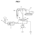
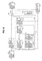
- Fig. 1 represents one embodiment of the case where the present invention is applied to a hydraulic circuit control system for a hydraulic excavator as a typical example of construction machines. Note that, for simplification of the description, Fig. 1 shows part of the hydraulic circuit control system that is related to a hydraulic cylinder for driving an arm of the hydraulic excavator.
- the hydraulic circuit control system of this embodiment comprises a hydraulic pump 1; an actuator 2 such as a hydraulic cylinder; a flow control valve 3 for controlling a direction and a flow rate of a hydraulic fluid delivered from the hydraulic pump 1 and flowing a hydraulic cylinder; proportional solenoid valves 3a, 3b for driving the flow control valve 3; a control lever device 4 including a control lever 4a and outputting an electrical operational signal instructing the flow rate through the flow control valve 3; and a control unit 5 for outputting drive signals to the proportional solenoid valves 3a, 3b in accordance with the operational signal from the control lever device 4 and driving the flow control valve 3.
- the actuator 2 is shown as a hydraulic cylinder for driving an arm 6a of a working device of a hydraulic excavator 6, but it may be another actuator for driving another component of the working device.
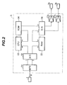
- Fig. 2 shows a configuration of the control unit 5.
- the control unit 5 comprises a ROM memory 54 for storing a program instructing overall control procedures of the control unit 5; a CPU 53 for controlling the entirety of the control unit in accordance with the program stored in the ROM memory 54; a multiplexer (MPX) 51 for selectively receiving signals outputted from the control lever device 4 in accordance with an instruction from the CPU 53; an A/D converter 52 for converting the signal inputted to the multiplexer 51 into a digital signal; a RAM memory 55 for temporarily storing numeral values, etc.
- MPX multiplexer
- a D/A converter 56 for converting a command value, provided as a digital value from the CPU 53, into an analog signal
- amplifiers 57a, 57b for amplifying the signal outputted from the D/A converter 56 and outputting the drive signals for the proportional solenoid valves 3a, 3b.
- Fig. 3 shows, in the form of a flowchart, control procedures (program) of the CPU 53 stored in the ROM 54 of the control unit 5. The control procedures will be described below following the flowchart of Fig. 3 .
- the CPU 53 first reads in block 100 an operational signal (referred to also as a lever signal hereinafter) ⁇ of the control lever device 4, and stores it in the RAM 55 temporarily. Then, in block 200, the read lever signal ⁇ is converted into a lever command value X. Then, in block 300, it is determined using a previously computed valve command value Y-1, which is a command value having been outputted at present, whether the valve command value Y-1 is within the range of ⁇ ⁇ not including boundary values ⁇ ⁇ at both ends of a neutral zone (referred to also as a "neutral zone ( ⁇ ⁇ )" hereinafter). That is to say, whether - ⁇ ⁇ Y-1 ⁇ ⁇ holds or not is determined. If it is determined in block 300 that the previously computed valve command value Y-1 is within the neutral zone, the CPU proceeds to block 400.
- a neutral zone referred to also as a "neutral zone ( ⁇ ⁇ )
- the lever command value X and the valve command values Y, Y-1 are described here.
- the lever command value X and the valve command values Y, Y-1 are each a command value for specifying a spool position of the flow control valve 3. More specifically, the lever command value X is a current input command value for the control lever device 4 before being subjected to arithmetic processing, and the valve command value Y is a command value obtained after the arithmetic processing described below.
- the actual spool position is controlled in accordance with the valve command value Y.
- the previously computed valve command value Y-1 is a valve command value computed by the processing in a cycle of the flowchart shown in Fig. 3 , which precedes one the current cycle. At present, the system is in a state just after a drive signal corresponding to the valve command value Y-1 has been outputted, and the spool position is being controlled in accordance with the valve command value Y-1.
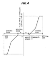
- Fig. 4 shows one example of the relationship between the valve command value Y and a flow rate q of the hydraulic fluid flowing through the flow control valve 3.
- the flow rate q through the flow control valve 3 is 0 when the valve command value Y is within the neutral zone ( ⁇ ⁇ ).
- the flow rate q is also increased as an absolute value of the valve command value Y increases.
- the relationship of the valve command value Y versus the flow rate q, shown in Fig. 4 represents general one, and there is an optimum relationship for each actuator to be controlled. Further, the relationship may be set so as to provide different characteristics depending on the operating direction.
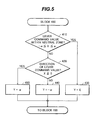
- Fig. 5 shows details of block 400. Since it is determined in block 300 (see Fig. 3 ) that the previously computed valve command value Y-1 (current operation command value) is within the neutral zone, the valve command value Y for the neutral zone is computed in block 400.
- the CPU first determines in block 410 whether the lever command value X (current lever input command value) is within the range of ⁇ ⁇ including the boundary values ⁇ ⁇ at both the ends of the neutral zone (referred to also as a "neutral zone ( ⁇ ⁇ )" hereinafter). That is to say, whether - ⁇ ⁇ X - ⁇ ⁇ is satisfied or not is determined. If the determination result in block 410 is "Yes”, this means that the valve command value Y-1 (current operation command value) and the lever command value X (current lever input command value) are both within the neutral zone ( ⁇ ⁇ ). If it is "No”, this means that the valve command value Y-1 is within the neutral zone, but the lever command value X has passed the neutral zone.
- the CPU proceeds to block 430.
- the valve command value Y is set to be equal to the lever command value X.
- the valve command value Y is set to be equal to the lever command value X as it is.
- the CPU proceeds to block 420.
- valve command value Y-1 current operation command value
- the processing goes to block 500.
- the valve command value Y for a driving zone is computed.
- Fig. 6 shows details of block 500.
- an execution time of one cycle of the control processing shown in Fig. 3 is ⁇ t
- an actual change rate of the lever command value X is expressed by ⁇ X/ ⁇ t.
- ⁇ t is a substantially constant value and it is convenient to employ a maximum setting rate ⁇ Y (described later), which is to be compared with ⁇ X, as a change rate in the same cycle, ⁇ X is directly employed as the change rate of the lever command value X.
- the CPU determines in which one of three conditions, i.e., (1) acceleration, (2) deceleration/stop, and (3) lever reversed, the operating status of the hydraulic excavator is.
- the processing goes to block 530.
- a maximum setting rate AY in acceleration is computed.
- the absolute value of the maximum setting rate ⁇ Y is increased as the absolute value of the lever command value X, i.e., the lever shift amount, increases. Additionally, the relationship between both the values may be set such that, as shown in Fig. 7(b) ,
- the processing goes to block 521.
- the current moving direction of the actuator is determined based on the sign of the previously computed valve command value Y-1 (current operation command value). If the previously computed valve command value Y-1 is determined as being positive (+) (Y-1 ⁇ 0), the processing goes to block 523.
- the direction in which the control lever 4a is manipulated is determined from whether the lever command value X is on the positive (+) side with respect to the neutral zone (X ⁇ - ⁇ ). If the lever command value X is determined as being on the positive (+) side, the processing goes to block 531.
- a maximum setting rate ⁇ Y in deceleration/stop is computed.
- any other suitable method such as storing a function formula and putting the lever command value X in the formula to calculate ⁇ Y, is also usable.
- the relationship between the lever command value X and the maximum setting rate ⁇ Y is preferably set such that, as shown in Fig. 8 , the absolute value of the maximum setting rate ⁇ Y is increased as the absolute value of the lever command value X, i.e., the lever shift amount, decreases and the lever command value X approaches the neutral zone. Additionally, as with the above case, the relationship between both the values may be set such that ⁇ Y is increased in a stepwise manner as
- a minimum value ⁇ Ymin2 of the maximum setting rate in this case is preferably set to satisfy ⁇ Ymin2 ⁇ ⁇ Ymin1 with respect to a minimum value ⁇ Ymin1 of the maximum setting rate in acceleration so that the actuator is quickly brought into a standstill when it is to be stopped.
- the relationship between the lever command value X and the maximum setting rate ⁇ Y is preferably set such that, as shown in Fig. 9 , the maximum setting rate AY has a constant large value regardless of the magnitude of the lever command value X.
- the relationship between both the values may be set such that ⁇ Y is changed gradually or stepwisely depending on the value of X.
- a minimum value ⁇ Ymin3 of the maximum setting rate in this case is preferably set to satisfy ⁇ Ymin3 ⁇ ⁇ Ymin2 with respect to the minimum value ⁇ Ymin2 of the maximum setting rate in deceleration/stop so that the moving direction of the actuator can be reversed with a good response in the lever-reversed operation.
- valve command value Y-1 is determined in block 521 as being negative (-)
- the processing goes to block 522.
- the direction in which the control lever 4a is manipulated is determined from whether the lever command value X is on the negative (-) side with respect to the neutral zone (X ⁇ ⁇ ). If the lever command value X is determined as being on the negative (-) side, the processing goes to block 533.
- a maximum setting rate ⁇ Y in deceleration/stop is computed.
- the relationship between the lever command value X and the maximum setting rate ⁇ Y is preferably set such that, as shown in Fig. 8 , the absolute value of the maximum setting rate ⁇ Y is increased as the absolute value of the lever command value X, i.e., the lever shift amount, decreases and the lever command value X approaches the neutral zone.
- the relationship between both the values is not always required to be a function expressed by fmax21 but having an opposite sign, and may be set to optimum one from the viewpoint of providing a better operation feeling.
- a maximum value ⁇ Ymax2 of the maximum setting rate in this case is preferably set to satisfy ⁇ Ymax2 > ⁇ Ymax1 with respect to a maximum value ⁇ Ymax1 of the maximum setting rate in acceleration so that the actuator is quickly brought into a standstill when it is to be stopped.
- a maximum setting rate AY in the lever-reversed condition is computed.
- the maximum setting rate ⁇ Y has a constant large value regardless of the magnitude of the lever command value X.
- the relationship between both the values is not always required to be a function expressed by fmax31 but having an opposite sign, and may be set to optimum one from the viewpoint of providing a better operation feeling. That relationship may be set such that ⁇ Y is changed gradually or stepwisely depending on the value of X.
- ⁇ Y may be computed using either a table or a calculation formula.
- a maximum value ⁇ Ymax3 of the maximum setting rate in this case is preferably set to satisfy ⁇ Ymax3 > ⁇ Ymax2 with respect to the maximum value ⁇ Ymax2 of the maximum setting rate in deceleration/stop so that the moving direction of the actuator can be reversed with a good response in the lever-reversed operation.
- the valve command value Y is computed using the change rate ⁇ X of the lever command value X or the maximum setting rate ⁇ Y that are obtained in the above processing.
- the lever command value change rate ⁇ X is compared with the maximum setting rate ⁇ Y. If
- the valve command value Y the lever command value X is set.
- valve command value Y is converted into valve drive signals for the solenoid proportional valves 3a, 3b, and the valve drive signals are outputted to control the flow control valve 3.
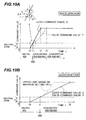
- Figs. 10(a) and 10(b) show time charts in the case manipulating the control lever 4a to the positive (+) side from a neutral condition.
- a solid line represents a signal from the control lever 4a (lever command value X)
- a one-dot-chain line represents the valve command value Y obtained through the control processing in this embodiment.
- Fig. 10(a) represents the case of manipulating the control lever 4a quickly, i.e., the situation where
- the processing of block 542 within block 500 is executed and, as indicated by the one-dot-chain line, the valve command value Y is increased in accordance with the value of ⁇ Y after the time t1.
- the change rate of the valve command value is held to be not larger than ⁇ Y, thus enabling the actuator 2 to start up (accelerate) without any shock at a speed at which the operator feels no delay in the operation.
- AY is a function of the lever command value X
- an optimum maximum change rate can be set depending on the lever command value X (value of the operational signal), and an appropriate feeling in acceleration corresponding to the input amount upon shift of the control lever 4a can be provided.
- the maximum setting rate is not restrained based on the maximum change rate while the valve command value Y-1 is within the neutral zone, no delay occurs in increase of the flow rate through the control valve with respect to the lever command value X.
- Fig. 10(b) represents the case of manipulating the control lever 4a moderately.
- the change rate ⁇ X of the lever signal upon manipulation of the control lever is smaller than the maximum setting rate ⁇ Y (
- the processing of block 541 within block 500 is executed and, as shown in Fig. 10(b) , the valve command value Y coincides with the lever command value X.
- the operator can therefore start up (accelerate) the actuator 2 with a desired feeling in acceleration.
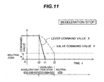
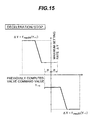
- Fig. 11 represents the case of returning the control lever 4a quickly from the maximum shift position to the neutral position for stopping the actuator.
- ) of block 520 within block 500 are negated, whereby the operating status is determined as being in deceleration/stop as indicated by block 531 within block 500. Therefore, the maximum setting rate is computed in accordance with the function ⁇ Y fmax21(X) shown in Fig. 8 .
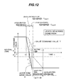
- Fig. 12 represents the case of manipulating the control lever 4a quickly from a maximum value on the positive (+) side to a minimum value (maximum absolute value) on the negative (-) side during a time period from t0 to t2 (referred to as a lever-reversed operation).
- valve command value Y is decreased in accordance with the value of ⁇ Y through the processing of block 542 within block 500.
- the "computation of maximum setting rate in lever-reversed condition" of block 532 is executed after that.
- the term "lever-reversed operation” means an operation performed when it is required to quickly change the moving direction of the working device in the case of, e.g., dropping mud from a bucket, bumping a boom against a vertical surface, or avoiding a risk, and a rapid response is demanded until the working device changes the moving direction. After the moving direction of the working device has changed and become coincident with the operating direction, the operation having such characteristics as being not slow and free from shocks is desired as with ordinary works.
- the minimum value ⁇ Ymin3 of the maximum setting rate ⁇ Y in the lever-reversed condition is set to satisfy ⁇ Ymin3 ⁇ ⁇ Ymin2 with respect to the minimum value ⁇ Ymin2 of the maximum setting rate in deceleration/stop so that the moving direction of the working device can be reversed with a good response.
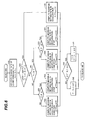
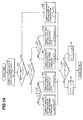
- Fig. 13 is a functional block diagram for the control processing in the control unit 5.
- block 900 "computation of lever command value” corresponds to blocks 100, 200 in Fig. 3 .
- Block 910 indicated by a two-dot-chain line corresponds to block 300 in Fig. 3 , and comprises block 910a "determination of neutral dead zone” and a processing changeover switch 910b.
- Block 911 "computation of valve command value for neutral dead zone” corresponds to block 400 in Fig. 3 .
- Block 912 indicated by a two-dot-chain line corresponds to block 500 in Fig. 3 .
- block 920 "computation of change rate of lever command value” corresponds to block 510 in Fig.
- block 940 "storing of valve command value” corresponds to block 700 in Fig. 3
- block 950 corresponds to block 800 in Fig. 3 .
- block 921 in Fig. 13 corresponds to first determining means for determining the operating status of a construction machine based on an operational signal.
- Block 922 constitutes first processing means for setting therein an optimum maximum change rate of a control signal for the flow control valve beforehand for each operating status of the construction machine, determining the optimum maximum change rate adapted for the operating status of the construction machine at that time based on a determination result of the first determining means, and setting the determined optimum maximum change rate as a maximum change rate of the control signal for the flow control valve.
- block 910 (block 910a and processing changeover switch 910b) in Fig. 13 constitutes second determining means for determining whether a value of the control signal for the flow control valve is within the neutral zone.
- Block 911 constitutes second processing means for computing the control signal in accordance with the operational signal when the value of the control signal for the flow control valve is within the neutral zone of the flow control valve, instead of executing the processing to restrain the change rate of the control signal in accordance with the maximum change rate.
- the flow control valve in a system of controlling the flow control valve 3 with an electrical operational signal to control the operation of the actuator 2, the flow control valve can be controlled at an optimum maximum change rate in any operating status of acceleration, deceleration/stop, and lever-reversed condition with resulting characteristics cited below:
- the maximum change rate of the flow control valve 3 can be controlled as desired with proper manipulation of the control lever 4a, and an appropriate feeling in acceleration and deceleration corresponding to the input amount upon shift of the control lever 4a can be provided.
- the operation undergoing an even lesser shock can be performed by stopping the control lever 4a for a while just before a point in time at which the operational signal becomes 0 (i.e., a lever position just before a point in time at which the maximum change rate reaches ⁇ Ymin2 in Fig. 8 ) when the control lever 4a is returned, thereby slightly suppressing the maximum change rate, and then finally returning the control lever 4a to 0.
- Fig. 14 shows a second embodiment of the present invention. This second embodiment differs from the above first embodiment in that block 500 shown in Fig. 3 is replaced by block 500B shown in Fig. 14 .
- Fig. 14 sub-blocks having the same functions as those of block 500 detailed in Fig. 6 are denoted by the same numerals.
- Blocks 531B, 533B in Fig. 14 have different functions from blocks 531, 533 of Fig. 6 in the above first embodiment.
- Blocks 531B, 533B are each block for "computation of maximum setting rate in deceleration/stop" executed when the operating status is in the condition of deceleration or stop.
- the maximum setting rate is set such that the absolute value
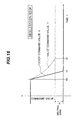
- Fig. 16 shows an actual operation implemented using one of those functions.
- the valve command value Y is changed at a rate that decreases as it returns toward the neural zone.
- the working device is not only slowed down just before stopping so as to alleviate a shock, but also brought into a standstill without causing the operator to feel a delay in motion because an initial value of the maximum setting rate is relatively large.
- the flow control valve in a system of controlling a flow control valve with an electrical operational signal to control the operation of an actuator, since an optimum maximum setting rate is computed based on determination of the operating status, the flow control valve can be controlled at the optimum maximum change rate in any operating status of acceleration, deceleration/stop, and lever-reversed condition with resulting characteristics cited below:
- the optimum maximum change rate is set depending on a value of an operational signal, an appropriate feeling in acceleration and deceleration corresponding to the input amount upon shift of the control lever can be provided.
- the machine undergoes a less shock around a point in time at which the moving speed of the actuator is reversed, and the operation can be performed without causing the operator to feel neither a delay in the operation nor a pause in the operation in the vicinity of the neutral position.
- the optimum maximum change rate is set depending both the value of the operational signal and a previously outputted control signal, an appropriate feeling in acceleration and deceleration corresponding to the input amount upon shift of the control lever can be provided.
Landscapes
- Engineering & Computer Science (AREA)
- General Engineering & Computer Science (AREA)
- Mining & Mineral Resources (AREA)
- Civil Engineering (AREA)
- Structural Engineering (AREA)
- Physics & Mathematics (AREA)
- Fluid Mechanics (AREA)
- Chemical & Material Sciences (AREA)
- Analytical Chemistry (AREA)
- Mechanical Engineering (AREA)
- Operation Control Of Excavators (AREA)
- Fluid-Pressure Circuits (AREA)
Applications Claiming Priority (3)
| Application Number | Priority Date | Filing Date | Title |
|---|---|---|---|
| JP21482599A JP3940242B2 (ja) | 1999-07-29 | 1999-07-29 | 建設機械の油圧回路制御装置 |
| JP21482599 | 1999-07-29 | ||
| PCT/JP2000/005026 WO2001009440A1 (en) | 1999-07-29 | 2000-07-27 | Hydraulic circuit control device of construction machinery |
Publications (3)
| Publication Number | Publication Date |
|---|---|
| EP1126087A1 EP1126087A1 (en) | 2001-08-22 |
| EP1126087A4 EP1126087A4 (en) | 2003-04-23 |
| EP1126087B1 true EP1126087B1 (en) | 2010-01-06 |
Family
ID=16662166
Family Applications (1)
| Application Number | Title | Priority Date | Filing Date |
|---|---|---|---|
| EP00948253A Expired - Lifetime EP1126087B1 (en) | 1999-07-29 | 2000-07-27 | Hydraulic circuit control device of construction machinery |
Country Status (7)
| Country | Link |
|---|---|
| US (1) | US6430490B1 (enExample) |
| EP (1) | EP1126087B1 (enExample) |
| JP (1) | JP3940242B2 (enExample) |
| KR (1) | KR100428883B1 (enExample) |
| CN (1) | CN1183304C (enExample) |
| DE (1) | DE60043649D1 (enExample) |
| WO (1) | WO2001009440A1 (enExample) |
Families Citing this family (12)
| Publication number | Priority date | Publication date | Assignee | Title |
|---|---|---|---|---|
| JP3805200B2 (ja) * | 2001-02-02 | 2006-08-02 | 株式会社クボタ | 作業車 |
| JP2003150261A (ja) * | 2001-11-15 | 2003-05-23 | Alps Electric Co Ltd | ダンパー力付与操作制御装置 |
| US6965822B2 (en) * | 2002-07-19 | 2005-11-15 | Cnh America Llc | Work vehicle including startup control current calibration mechanism for proportional control systems |
| US7287620B2 (en) * | 2004-07-13 | 2007-10-30 | Caterpillar S.A.R.L. | Method and apparatus for controlling the speed ranges of a machine |
| AT502348B1 (de) * | 2005-08-17 | 2008-09-15 | Voest Alpine Ind Anlagen | Regelungsverfahren und regler für ein mechanisch- hydraulisches system mit einem mechanischen freiheitsgrad pro hydraulischem aktuator |
| JP4804137B2 (ja) * | 2005-12-09 | 2011-11-02 | 株式会社小松製作所 | 作業車両のエンジン負荷制御装置 |
| US8364354B2 (en) * | 2008-10-24 | 2013-01-29 | Deere & Company | Blade speed control logic |
| CN104956006B (zh) * | 2012-12-13 | 2017-10-03 | 现代建设机械(株) | 用于基于操纵杆控制的建筑设备的自动控制系统和方法 |
| KR101483457B1 (ko) | 2013-10-30 | 2015-01-16 | 한국도키멕 주식회사 | 레디얼 피스톤 펌프 제어시스템 및 방법 |
| IT201900005238A1 (it) * | 2019-04-05 | 2020-10-05 | Cnh Ind Italia Spa | Procedimento di controllo per l'attuazione di un movimento di almeno uno tra un braccio ed un attrezzo collegato al braccio in una macchina operatrice azionata da un motore, sistema di controllo corrispondente e macchina operatrice comprendente tale sistema di controllo |
| US20240044108A1 (en) * | 2020-08-28 | 2024-02-08 | Nec Corporation | Work control method of construction machine, work control system, and work control apparatus |
| CN114810696B (zh) * | 2022-04-28 | 2025-04-22 | 柳州柳工挖掘机有限公司 | 液压系统、控制方法和轮式挖掘机 |
Family Cites Families (15)
| Publication number | Priority date | Publication date | Assignee | Title |
|---|---|---|---|---|
| JPS58165585A (ja) * | 1982-03-26 | 1983-09-30 | Hitachi Constr Mach Co Ltd | 油圧回路の制御装置 |
| JPS58192986A (ja) * | 1982-04-07 | 1983-11-10 | Hitachi Constr Mach Co Ltd | 油圧回路の制御装置 |
| US4400937A (en) * | 1982-09-29 | 1983-08-30 | Deere & Company | Control for quickly effecting displacement changes in a pump supplying fluid to primary and secondary function control valves |
| JPS6030491A (ja) * | 1983-07-29 | 1985-02-16 | Hitachi Constr Mach Co Ltd | 油圧ポンプの故障診断装置 |
| JPS6213542A (ja) | 1985-07-10 | 1987-01-22 | Daido Steel Co Ltd | 金属回収方法 |
| JPS6239295A (ja) | 1985-08-14 | 1987-02-20 | 株式会社 熊平製作所 | 個人確認装置 |
| US4801247A (en) * | 1985-09-02 | 1989-01-31 | Yuken Kogyo Kabushiki Kaisha | Variable displacement piston pump |
| JP2900286B2 (ja) * | 1990-10-31 | 1999-06-02 | 富士重工業株式会社 | 無段変速機の制御装置 |
| US5249422A (en) * | 1991-12-20 | 1993-10-05 | Caterpillar Inc. | Apparatus for calibrating the speed of hydrostatically driven traction motors |
| JP2682925B2 (ja) * | 1992-01-20 | 1997-11-26 | 株式会社クボタ | 土工機における油圧アクチュエータ制御装置 |
| JPH05195554A (ja) * | 1992-01-20 | 1993-08-03 | Kubota Corp | 土工機における油圧アクチュエータ制御装置 |
| JPH0712104A (ja) * | 1993-06-21 | 1995-01-17 | Hitachi Constr Mach Co Ltd | 油圧機械の駆動制御装置 |
| JPH07107279A (ja) | 1993-10-01 | 1995-04-21 | Canon Inc | 画像処理装置 |
| US5701793A (en) * | 1996-06-24 | 1997-12-30 | Catepillar Inc. | Method and apparatus for controlling an implement of a work machine |
| JP3586516B2 (ja) * | 1996-07-22 | 2004-11-10 | 株式会社神戸製鋼所 | 操作制御装置及び操作制御方法 |
-
1999
- 1999-07-29 JP JP21482599A patent/JP3940242B2/ja not_active Expired - Fee Related
-
2000
- 2000-07-27 DE DE60043649T patent/DE60043649D1/de not_active Expired - Lifetime
- 2000-07-27 WO PCT/JP2000/005026 patent/WO2001009440A1/ja not_active Ceased
- 2000-07-27 CN CNB008015643A patent/CN1183304C/zh not_active Expired - Fee Related
- 2000-07-27 US US09/806,200 patent/US6430490B1/en not_active Expired - Lifetime
- 2000-07-27 EP EP00948253A patent/EP1126087B1/en not_active Expired - Lifetime
- 2000-07-27 KR KR10-2001-7003879A patent/KR100428883B1/ko not_active Expired - Fee Related
Also Published As
| Publication number | Publication date |
|---|---|
| CN1183304C (zh) | 2005-01-05 |
| KR100428883B1 (ko) | 2004-04-29 |
| WO2001009440A1 (en) | 2001-02-08 |
| US6430490B1 (en) | 2002-08-06 |
| EP1126087A4 (en) | 2003-04-23 |
| JP2001040712A (ja) | 2001-02-13 |
| JP3940242B2 (ja) | 2007-07-04 |
| EP1126087A1 (en) | 2001-08-22 |
| KR20010079934A (ko) | 2001-08-22 |
| CN1319153A (zh) | 2001-10-24 |
| DE60043649D1 (de) | 2010-02-25 |
Similar Documents
| Publication | Publication Date | Title |
|---|---|---|
| EP1126087B1 (en) | Hydraulic circuit control device of construction machinery | |
| EP0695875B1 (en) | Hydraulic pump controller | |
| US6546724B2 (en) | Work machine including finely adjustable operation modes | |
| KR101948465B1 (ko) | 건설 기계의 제어 장치 | |
| US6230090B1 (en) | Interference prevention system for two-piece boom type hydraulic excavator | |
| EP2660478B1 (en) | Boom-swivel compound drive hydraulic control system of construction machine | |
| JPS6261742B2 (enExample) | ||
| US7048515B2 (en) | Hydraulic drive system and method using a fuel injection control unit | |
| JP2511925B2 (ja) | 建設機械のエンジン回転数制御装置 | |
| EP1231386A1 (en) | Hydraulic drive device | |
| EP1398512B1 (en) | Hydraulic driving unit for working machine, and method of hydraulic drive | |
| JP3586516B2 (ja) | 操作制御装置及び操作制御方法 | |
| JP7314404B2 (ja) | 作業機械 | |
| JP2001050202A (ja) | 油圧作業機の油圧制御装置 | |
| JP3730336B2 (ja) | 油圧アクチュエータの速度制御装置 | |
| JP2011021694A (ja) | 作業機械の旋回油圧制御装置 | |
| JP2509311B2 (ja) | 建設機械の作業機制御方法 | |
| JP2839567B2 (ja) | 建設機械の油圧駆動装置 | |
| JP7337632B2 (ja) | バルブシステム、作業機械、バルブの制御方法、プログラム、および記録媒体 | |
| JP2001020325A (ja) | アクチュエータ駆動制御装置 | |
| JP2576993B2 (ja) | 操作装置 | |
| JP2695335B2 (ja) | 土工機における油圧アクチュエータ制御装置 | |
| JPH04353130A (ja) | 油圧作業機械における作業装置の振動抑制制御装置 | |
| JP2633095B2 (ja) | 油圧建設機械の油圧制御装置 | |
| JP4974211B2 (ja) | 操作応答性能制御装置および作業機械 |
Legal Events
| Date | Code | Title | Description |
|---|---|---|---|
| PUAI | Public reference made under article 153(3) epc to a published international application that has entered the european phase |
Free format text: ORIGINAL CODE: 0009012 |
|
| AK | Designated contracting states |
Kind code of ref document: A1 Designated state(s): AT BE CH CY DE DK ES FI FR GB GR IE IT LI LU MC NL PT SE |
|
| AX | Request for extension of the european patent |
Free format text: AL;LT;LV;MK;RO;SI |
|
| 17P | Request for examination filed |
Effective date: 20010727 |
|
| A4 | Supplementary search report drawn up and despatched |
Effective date: 20030306 |
|
| RIC1 | Information provided on ipc code assigned before grant |
Ipc: 7F 15B 11/08 B Ipc: 7E 02F 9/22 B Ipc: 7E 02F 9/20 A |
|
| RBV | Designated contracting states (corrected) |
Designated state(s): DE FR GB IT SE |
|
| 17Q | First examination report despatched |
Effective date: 20071121 |
|
| GRAP | Despatch of communication of intention to grant a patent |
Free format text: ORIGINAL CODE: EPIDOSNIGR1 |
|
| GRAS | Grant fee paid |
Free format text: ORIGINAL CODE: EPIDOSNIGR3 |
|
| GRAA | (expected) grant |
Free format text: ORIGINAL CODE: 0009210 |
|
| AK | Designated contracting states |
Kind code of ref document: B1 Designated state(s): DE FR GB IT SE |
|
| REG | Reference to a national code |
Ref country code: GB Ref legal event code: FG4D |
|
| REF | Corresponds to: |
Ref document number: 60043649 Country of ref document: DE Date of ref document: 20100225 Kind code of ref document: P |
|
| PG25 | Lapsed in a contracting state [announced via postgrant information from national office to epo] |
Ref country code: SE Free format text: LAPSE BECAUSE OF FAILURE TO SUBMIT A TRANSLATION OF THE DESCRIPTION OR TO PAY THE FEE WITHIN THE PRESCRIBED TIME-LIMIT Effective date: 20100106 |
|
| PLBE | No opposition filed within time limit |
Free format text: ORIGINAL CODE: 0009261 |
|
| STAA | Information on the status of an ep patent application or granted ep patent |
Free format text: STATUS: NO OPPOSITION FILED WITHIN TIME LIMIT |
|
| 26N | No opposition filed |
Effective date: 20101007 |
|
| REG | Reference to a national code |
Ref country code: FR Ref legal event code: ST Effective date: 20110331 |
|
| PG25 | Lapsed in a contracting state [announced via postgrant information from national office to epo] |
Ref country code: FR Free format text: LAPSE BECAUSE OF NON-PAYMENT OF DUE FEES Effective date: 20100802 |
|
| PGFP | Annual fee paid to national office [announced via postgrant information from national office to epo] |
Ref country code: DE Payment date: 20140724 Year of fee payment: 15 |
|
| PGFP | Annual fee paid to national office [announced via postgrant information from national office to epo] |
Ref country code: GB Payment date: 20140723 Year of fee payment: 15 |
|
| PGFP | Annual fee paid to national office [announced via postgrant information from national office to epo] |
Ref country code: IT Payment date: 20140714 Year of fee payment: 15 |
|
| REG | Reference to a national code |
Ref country code: DE Ref legal event code: R119 Ref document number: 60043649 Country of ref document: DE |
|
| GBPC | Gb: european patent ceased through non-payment of renewal fee |
Effective date: 20150727 |
|
| PG25 | Lapsed in a contracting state [announced via postgrant information from national office to epo] |
Ref country code: DE Free format text: LAPSE BECAUSE OF NON-PAYMENT OF DUE FEES Effective date: 20160202 Ref country code: GB Free format text: LAPSE BECAUSE OF NON-PAYMENT OF DUE FEES Effective date: 20150727 Ref country code: IT Free format text: LAPSE BECAUSE OF NON-PAYMENT OF DUE FEES Effective date: 20150727 |